35 PE - Appareil photo MINOX - Notice d'utilisation et mode d'emploi gratuit
Retrouvez gratuitement la notice de l'appareil 35 PE MINOX au format PDF.


| Type de produit | Appareil photo compact 35 mm |
| Marque | Minox |
| Modèle | 35 PE |
| Format de film | 135 (35 mm) |
| Objectif | Minox 35 mm f/2,8 |
| Mise au point | Manuelle par télémètre couplé |
| Obturateur | Électronique, vitesses de 1/500 s à 30 s |
| Pose | Pose B |
| Sensibilité film | ISO 25 à 1600 |
| Alimentation | 2 piles au lithium LR44 (ou équivalent) |
| Dimensions | 100 x 60 x 30 mm |
| Poids | 200 g environ (sans piles) |
| Matériau | Corps en alliage d'aluminium |
| Flash intégré | Oui, nombre guide 12 (ISO 100) |
| Viseur | Viseur télémétrique à cadre clair |
| Compteur de vues | Automatique, remise à zéro à l'ouverture |
| Entretien et nettoyage | Nettoyer l'objectif avec un chiffon doux non pelucheux, stocker dans un endroit sec |
| Sécurité | Retirer les piles en cas de non-utilisation prolongée |
| Pièces détachées et réparabilité | Pièces disponibles auprès de services spécialisés |
FOIRE AUX QUESTIONS - 35 PE MINOX
Questions des utilisateurs sur 35 PE MINOX
0 question sur cet appareil. Repondez a celles que vous connaissez ou posez la votre.
Poser une nouvelle question sur cet appareil
Téléchargez la notice de votre Appareil photo au format PDF gratuitement ! Retrouvez votre notice 35 PE - MINOX et reprennez votre appareil électronique en main. Sur cette page sont publiés tous les documents nécessaires à l'utilisation de votre appareil 35 PE de la marque MINOX.
MODE D'EMPLOI 35 PE MINOX
MINOX
35 PE
Type 10730
Ersatzteile
Reparatur
Spare Parts
Repairs
Pièces de rechange
Réparation
Repuestos
Reparación
MINOX GmbH Optische und Feinmechanische Werke
Postfach 6020. D 63 Giessen 1
Tel. (O641) 61071
Telex 482986 minox d
E


Following Numbers have been changed:
| 10850 | 35000 in 10750 | 35000 | VN |
| 10800 | 68000 in 10750 | 68000 | PHOTECTICS LINE |
| 10720 | 19400in | 10720 | PLIIIC |
| 10720 | 50400 in | 10720 | PL III lens |
| 10800 | 53200 in | 10720 | First Magnet plane |
-,20
| Following Numbers have been changed | |||||
| PO 2375 | 22090 | 01521 | in | 22090 | 01529 |
| 02209 | 03332 | in | 02209 | 33332 | |
| PO 2373 PF | 10730 | 19400 | in | 10730 | 19450 |
| PE | 10730 | 50400 | in | 10730 | 50450 |
| FE | 00000 | 33021 | in | 10750 | 01004 |
| EC No | 01080 | 01005 | in | 10750 | 01005 |
| EC No. | 01080 | 45000 | in | 10750 | 44000 |
| EC No | 10850 | 12019 | in | 10750 | 12019 |
No. 02209 01589 not available as separate part, this is integrated in back cover No. 22090 03333
35 PE


| Bild-NrFig no | Stck qty. | Teilebezeichnung / Part nameDesignation / Designacion | Teil-Nr/Part no/No.de piece/No de pieza |
| 1 | 1 | Body cap, mounted | 10730 38000 |
| 2 | 1 | Frame counter window | 10750 38002 |
| 3 | 1 | Push-button | 10720 38022 |
| 4 | 3 | Hood | 10720 38009 |
| 5 | 4 | Screw, countersunk machineBg 1.6 x 2.5 mm | 10800 40003 |
| S | Screw, countersunk machineM 2 x 2.5 mm | 00300 80050 | |
| 6 | 1 | Screw, countersunk machineBg 1.6 x 4 mm | 10800 40004 |
| S | Screw, countersunk machineM 2 x 4 mm | 00301 65014 | |
| 7 | 1 | Screw, countersunk machineM 1.4 x 2.5 mm | 10750 12048 |
| 8 | 1 | Sliding switch 2 x, complete | 10850 46000 |
| 9 | 1 | Shutter release button, green | 10720 40001 |
| 10 | 1 | Shutter release pin | 10750 03001 |
| 11 | 1 | Shutter release spring | 10800 03002 |
| 12 | 1 | Printed circuit board, complete | 10730 19400 |
| 13 | 1 | Sleeve | 10750 16007 |
| 14 | 1 | Viewfinder, complete | 10730 20000 |
| 15 | 1 | Front lens element I | 10800 18111 |
| 16 | 1 | Front lens element II | 10800 18002 |
| 17 | 1 | Viewfinder mask | 10720 18004 |
| 18 | 1 | Eyepiece | 10800 18113 |
| 19 | 2 | Light guide | 10720 04004 |
| 20 | 1 | Cover | 10750 18008 |
| 21 | 1 | Cover strip | 10730 18007 |
| 22 | 2 | Spacing sleeve | 10720 04014 |
| 23 | 2 | Retainer ring G 2.0 | 00310 72000 |
| 24 | 1 | Screw, fillister M 1.4 x 2 mm | 00301 32000 |
| 25 | 1 | Insulating tubing, long | 10800 12034 |
| 26 | 1 | Insulating tubing, short | 10800 12037 |
| 27 | 1 | Spool take-up cam, complete | 10800 14000 |
| 28 | 1 | Spool take-up cam | 10800 14001 |
| 29 | 1 | Take-up cam clip | 10800 14002 |
| 30 | 1 | Screw, shoulder | 10800 14003 |
| Bild-NrFig no | Stckqty | Teilebezeichnung / Part nameDesignation / Designacion | Teil-Nr/Part no/No.de piece/No de pieza |
| 31 | 1 | Washer 7.3 ø x 5.05 ø x 0.05 mm | 00310 30000 |
| 32 | 1 | Light-trap plate | 10730 12001 |
| 33 | 1 | Rewind cam | 10750 12124 |
| 34 | 1 | Stop spring | 10750 13101 |
| 35 | 1 | Crank arm, complete | 10750 11000 |
| 36 | 1 | Rewind cam cover | 10750 12026 |
| 37 | 1 | Screw, fillister M 2 x 4 mm | 00201 83050 |
| 38 | 1 | Base plate, complete | 10720 21400 |
| 39 | 1 | . Trim resistor R 10, see Page 22 | |
| 40 | 1 | . Resistor R 9, see Page 22 | |
| 41 | 1 | . Insulating tubing | 10800 21002 |
| 42 | 2 | Screw, fillister Bg 1.4 x 3mm | 00301 10050 |
| 43 | 1 | Retaining clip | 10750 12009 |
| 44 | 1 | Screw, fillister Bg 2.2 x 4 mm | 00301 36050 |
| 45 | 1 | Battery tube | 10800 12106 |
| 46 | (1) | Battery Varta V 27 PX Mallory PX 27 | |
| 47 | 1 | Battery cover | 10800 45000 |
| 48 | 1 | Film feed | 10750 39000 |
| 49 | 4 | Screw, countersunk machineM M 1.4 x 2.5 mm | 00300 99000 |
| 50 | 1 | Front flap PE | 10730 26014 |
| 51 | 2 | Grooved alignment pin | 00340 37050 |
| 52 | 2 | Latch pin | 10800 26016 |
| 53 | 1 | Body back | 10730 43000 |
| 54 | 1 | . DIN/ASA label | 10720 43002 |
| 55 | 1 | . Indicator disc | 10800 43006 |
| 56 | 1 | . Lock | 10850 43001 |
| 57 | 1 | . Spring washer | 10800 43005 |
| 58 | 1 | . Lock plate | 10800 43003 |
| 59 | 1 | . Retainer washer 2.3 | 00210 24000 |
| 60 | 1 | Disc | 10750 40005 |
35 PE


| Bild-NrFig no | Stck qty. | Teilebezeichnung / Part nameDesignation / Designacion | Teil-Nr/Part no/No.de piece/No de pieza |
| 101 | 1 | Body, riveted | 10730 01000 |
| 102 | 1 | . Rivet solder tag | 00330 21000 |
| 103 | 1 | . Negative contact | 10800 01005 |
| 104 | 1 | Shutter release block | 10800 12007 |
| 105 | 1 | Drag spring | 10800 12008 |
| 106 | 1 | Torsion spring | 10800 12011 |
| 107 | 1 | Re-set latch | 10800 12010 |
| 108 | 1 | Retainer ring G 1.5 | 00310 71000 |
| 109 | 1 | Winder pin | 10800 26001 |
| 110 | 1 | Base plate, complete | 10850 02000 |
| 111 | 1 | Screw, fillister M 1.4 x 6.5 mm | 10800 12044 |
| 112 | 1 | Torsion spring for conical spring washer | 10750 12041 |
| 113 | 1 | Conical spring washer | 10750 12040 |
| 114 | 2 | Torsion spring for tension latch | 10800 12043 |
| 115 | 2 | Tension latch | 10800 12042 |
| 116 | 1 | Winder wheel | 10800 12012 |
| 117 | 1 | Bottom plate | 10850 06003 |
| 118 | 1 | Screw, fillister Bg 2 x 3.5 mm | 00300 90000 |
| 119 | 1 | Angle bracket | 10750 12046 |
| 120 | 1 | Screw, fillister Bg 2 x 8.4 mm | 10800 12027 |
| (1) | Screw, fillister Bg 1.9 x 7.8 mm | 00301 40050 | |
| S | Screw, fillister M 2.3 x 8 mm | 00301 27050 | |
| 121 | 1 | Torsion spring | 10750 12047 |
| 122 | 1 | Stop latch | 10800 06001 |
| 123 | 1 | Retaining ring G 1.5 | 00310 71000 |
| 124 | 1 | Film counter wheel | 10750 12019 |
| 125 | 1 | Retainer ring G 2.0 | 00310 72000 |
| 126 | 1 | Flat spiral spring | 10800 12020 |
| 127 | 1 | Sliding switch, complete | 10720 09000 |
| 128 | 1 | Guide plate | 10800 12016 |
| 129 | 1 | Lining | 10800 12017 |
| 130 | 1 | Screw, fillister M 1.4 x 2 mm | 00301 31000 |
| 131 | 1 | Tension spring | 10800 12018 |
| Bild-NrFig no | Stck. qty. | Teilebezeichnung / Part nameDesignation / Designacion | Teil-Nr/Port no/No.de piece/No de pieza |
| 132 | 3 | Screw, countersunk machine M 1.6 x 5 mm | 00301 62014 |
| 133 | 1 | Screw, countersunk machineM 1.6 x 3.5 mm | 00301 64014 |
| 134 | 1 | Sleeve, complete | 10850 30200 |
| 135 | 1 | Washer, 9.5 ø x 6.9 ø x 0.3 mm | 00311 42000 |
| 136 | 1 | Expansion tube | 10850 36002 |
| 137 | 1 | Drive plate | 10750 36106 |
| 138 | 1 | Screw, countersunk machine Bg 1.6 x 2.5 mm | 10750 36020 |
| 139 | 1 | Cogwheel | 10750 36003 |
| 140 | 1 | Film transport wheel | 10750 36104 |
| 141 | 1 | Retainer washer 1.9 mm | 00210 84000 |
| 142 | 1 | Retainer ring G 2.0 | 00310 72000 |
| 143 | 1 | Idler wheel | 10850 36018 |
| 144 | 1 | Transfer wheel | 10800 36209 |
| 145 | 1 | Resistor plate, complete | 10720 35000 |
| 146 | 1 | . Adjusting knob | 10720 35003 |
| 147 | 1 | . Catch plate | 10850 33000 |
| 148 | 1 | . Retainer ring G 2.0 | 00310 72000 |
| 149 | 2 | Screw, fillister Bg 1.4 x 3.5 mm | 00301 22050 |
| 150 | 1 | Pressure spring | 10850 36010 |
| 151 | 1 | Latch pin | 10850 36016 |
| 152 | 1 | Drive cover | 10720 37000 |
| 153 | 1 | . Sliding lock | 10800 36131 |
| 154 | 1 | . Retainer ring G 1.5 | 00310 71000 |
| 155 | 1 | Screw, fillister Bg 2 x 2.8 mm | 10800 12028 |
| S | Screw, fillister M 2.3 x 3 mm | 00300 88050 | |
| 156 | 1 | Screw, countersunk machine Bg 2 x 5 mm | 10800 36014 |
| S | Screw, countersunk machine M 2 x 6 mm | 00201 13014 | |
| 157 | 1 | Screw, countersunk machine Bg 1.45 x 5mm | 00301 24014 |
| 158 | 1 | Unlocking button | 10730 02003 |
| 159 | 1 | Lock | 10730 02002 |
| 160 | 1 | Leg spring | 10730 02004 |
| 161 | 1 | Cover | 10730 02005 |
| 162 | 2 | Screw, countersunk machineBg 1.7 x 2.8 mm | 10730 02006 |
S = Substitute
| Bild-NrFig no | Stck. qty. | Teilebezeichnung / Part nameDesignation / Designacion | Teil-Nr./Part no./No.de piece/No de pieza |
| 163 | 1 | Reflector front plate | 10730 05300 |
| 164 | 1 | Diffuser PE | 10730 92563 |
| 165 | 1 | Contact spring | 10730 05012 |
| 166 | 1 | Flash electronics PE, complete | 10730 06000 |
| 167 | 1 | . Reflector PE | 10730 91408 |
| 168 | 1 | . Flash tube, see Page 24 | |
| 169 | 2 | . Silicon tubing rings 3 x 5 mm | 10730 92030 |
| 170 | 1 | . Photo-transistor, see Page 23 | |
| 171 | 1 | . Printed circuit board | 10730 04001 |
| 172 | 1 | Cover plate | 10730 05100 |
| 173 | 2 | Screw, countersunk machine | |
| Bg 1.7 x 2.8 mm | 10730 02006 | ||
| 174 | 1 | Plate | 10730 05009 |
| 175 | 1 | Pressure leaf spring | 10730 02009 |
| 176 | 1 | Guide piece | 10730 05006 |
| 177 | 1 | Battery contact spring I | 10730 02001 |
| 178 | 1 | Battery cover, complete | 10730 03000 |
| 179 | 1 | Lock spring | 10730 02007 |
| 180 | 1 | Floor plate | 10730 02008 |
| 181 | 3 | Screw, countersunk machine | |
| Bg 1.7 x 2.8 mm | 10730 02006 | ||
| S | Screw, cheesehead | ||
| Bg 1.7 x 3 mm | 10730 05007 | ||
| FCASH TURS COMPLETE | 10730 91243 | ||
| FCASH BOARD HOCO DOW IN | 10730 02010 |


| Bild-NrFig no | Stck. qty. | Teilebezeichnung / Part nameDesignation / Designacion | Teil-Nr/Part no/No.de piece/No de pieza |
| 301 | 1(1) | Metre ring, completeFeet ring, complete | 10750 8100010750 82000 |
| 302 | 3 | . Headless set screw M 1.4 x 5 mm | 00203 24050 |
| 303 | 3 | . Square nut M 1.4 | 10800 50005 |
| 304 | 1 | Index pin | 10720 50012 |
| 305 | 1 | Window | 10750 50006 |
| 306 | 1 | Spacer ring | 10750 50015 |
| 307 | 1 | Lens PL II, complete | 10720 50400 |
| 308 | 1 | . Front lens element, complete | 10750 80000 |
| 309 | 1 | . Corrugated ring | 10750 50011 |
| 310 | 1 | . Cover disc | 10720 50408 |
| 311 | 1(1)(1)(1)(1)(1)(1)(1)(1)(1)(1)(1)(1)(1)(1)(1)(1)(1)(1)(1)(1)(1)(1)(1)(1)(1)(1)(1)(1)(1)(1)(1)(1)(1)(1)(1)(1)(1)(1)(1)(1)(1)(1)(1)(1)(1)(1)(1)(1)(1)(1)(1) | . Compensation filter 7%Compensation filter 10%Compensation filter 15%Compensation filter 20%Compensation filter 25%Compensation filter 30%Compensation filter 35%Compensation filter 40%Compensation filter 45%Compensation filter 50%Compensation filter 55%Compensation filter 60%Compensation filter 65%Compensation filter 70%Compensation filter 75%Compensation filter 80%Compensation filter 85% | 10800 5000710800 5002010800 5002110800 5002210800 5002310800 5002410800 5002510800 5002610800 5002710800 5002810800 5002910800 5003010800 5003110800 5003210800 5003310800 5003410800 50035 |
| 312 | 2 | . Screw, fillister M 1.4 x 2 mm | 10800 50003 |
| 313 | 1 | . Butt screw | 10800 50002 |
| 314 | 1 | . Depth of focus control ring, complete | 10720 73400 |
| 315 | 1 | . Aperture control ring | 10720 79401 |
| 316 | 1 | . Shutter PL II, complete | 10720 72400 |


| Bild-NrFig no | Stck.qty. | Teilebezeichnung / Part nameDesignation / Designacion | Teil-Nr/Part no./No.de piece/No de pieza |
| 317 | 3 | .. Threaded insert | 10800 72003 |
| 318 | 1 | .. Central lens element, complete | 10750 71000 |
| 319 | 1 | .. Diaphragm leaf II | 10750 72002 |
| 320 | 1 | .. Diaphragm leaf I | 10750 70000 |
| 321 | 1 | .. Spacer | 10750 72404 |
| 322 | 3 | .. Shutter leaf | 10720 72401 |
| 323 | 3 | .. Screw, countersunk machineBg 1.4 x 5 mm | 00301 39014 |
| 324 | 1 | .. Achromatic lens, complete | 10750 63000 |
| 325 | 1 | .. Sliding disc | 10800 64010 |
| 326 | 1 | .. Switch disc II | 10800 62000 |
| 327 | 1 | .. Switch disc I | 10800 61000 |
| 328 | 1 | .. Filler base | 10800 57200 |
| 329 | 1 | .. Magnet I, complete | 10720 53400 |
| 330 | 1 | .. Magnet II, complete | 10800 53100 |
| 331 | 2 | .. . Coil | 10800 52000 |
| 332 | 1 | .. . Armature, 9.75 mm long, for Magnet I | 10720 53404 |
| 1 | .. . Armature, 9.81 mm long, for Magnet II | 10800 53003 | |
| (1) | .. . Armature, 9.78 mm long, for Magnet II | 10800 53103 | |
| (1) | .. . Armature, 9.77 mm long, for Magnet II | 10800 53104 | |
| (1) | .. . Armature, 9.76 mm long, for Magnet II | 10800 53105 | |
| 333 | 1-2 | .. . Adhesion point for Magnet I | 10720 53011 |
| 334 | 2 | .. . Permanent magnet | 10800 53005 |
| 335 | 2 | .. . Yoke I | 10800 58100 |
| 336 | 2 | .. . Yoke II | 10800 53002 |
| 337 | 2 | .. . Screw, fillister M 1.4 x 1.15 mm | 00300 82050 |
| 338 | 2 | .. Latch, complete | 10800 51200 |
| 339 | 2 | .. insulating plates | 10800 54001 |
| 340 | 1 | .. Contact spring I | 10800 54005 |
| 341 | 1 | .. Contact spring II | 10800 54002 |
| 342 | 1 | .. Adjuster plate | 10800 54004 |
| 343 | 2 | .. Printed circuit board | 10800 54003 |
| 344 | 1 | .. Screw, fillister M 1.4 x 2 mm | 00300 97013 |
| 345 | 1 | .. Screw, fillister M 1.4 x 1.8 | 00201 81014 |
| Bild-NkFig no | Stck.qty. | Teilebezeichnung / Part nameDesignation / Designacion | Teil-Nr./Part no./ No.de piece/No de pieza |
| Electronic components | |||
| Components on the camera printed circuit board: | |||
| IC | 1 | IC ULA 1 G 003 | 10750 16001 |
| T 1 | 1 | Transistor BCW 61 C | 00363 25090 |
| Th 1 | 1 | Thyristor BRX 48 | 00364 36090 |
| D 1 | 1 | LED green | 10720 16004 |
| S | LED green | 00363 99090 | |
| D 2 | 1 | LED orange | 10750 16008 |
| S | LED orange | 00363 89090 | |
| D 3 | 1 | LED red | 10720 16007 |
| S | LED red | 00364 33090 | |
| D 4 | 1 | Z diode 6V2 | 00362 33090 |
| D 6 | 1 | LED yellow | 10730 16005 |
| S | LED yellow | 00364 00090 | |
| D 7 | 1 | Diode | 10720 16006 |
| S | Diode | 00360 15090 | |
| D 8 | 1 | Z diode 2V8 | 00364 55090 |
| R 2 | 1 | Resistor 12 kOhm | 00361 88090 |
| R 3 | 1 | Resistor 1 MOhm | 00362 71090 |
| R 4 | 1 | Resistor 6.8 kOhm | 00361 87090 |
| (1) | Resistor 8.2 kOhm | 00363 98090 | |
| R 5 | 1 | Resistor 4.7 kOhm | 00363 80090 |
| R 6 | 1 | Resistor 4.7 kOhm | 00363 80090 |
| (1) | Resistor 3.3 kOhm | 00362 73090 | |
| (1) | Resistor 2.7 kOhm | 00361 85090 | |
| R 7 | 1 | Resistor 10 kOhm | 00361 83090 |
| R 11 | 1 | Resistor 1.5 kOhm | 00364 44090 |
| R 12 | 1 | Resistor 2.2 kOhm | 00362 34090 |
| R 13 | 1 | Resistor 270 kOhm | 00363 16090 |
| R 15 | 1 | Resistor 22 kOhm | 00364 62090 |
| R 16 | 1 | Resistor 1 kOhm | 00363 17090 |
| Bild-NrFig no | Stck.qty. | Teilebezeichnung / Part nameDesignation / Designacion | Teil-Nr/Part no/No.de piece/No de pieza |
| 346 | 4 | .. Screw, countersunk machineM 1.4 x 1.6 mm | 00300 95050 |
| 347 | 3 | .. Base | 10720 64401 |
| 348 | 2 | .. Tension spring | 10720 55402 |
| 349 | 1 | .. Tension spring, 31 p, copper | 10720 64403 |
| 350 | 1 | .. Tension spring, 110 p | 10800 64005 |
| 351 | 1 | .. Diode D 5, see Page 23 | |
| 352 | 1 | . Photo resistor | 10720 68400 |
| 353 | 1 | . Insulating tubing | 10800 78020 |
| 354 | 1 | . Lens barrel | 10730 78401 |
| 355 | 1 | . Light cover | 10720 76400 |
| 356 | 1 | . Retainer clip, complete | 10720 75400 |
| 357 | 2 | . Washer 4.5 ø x 1.52 ø 0.05 mm | 00311 13050 |
| 358 | 2 | . Screw, fillister M 1.4 x 1.5 mm | 00301 58019 |
| 359 | 1 | . Winder link | 10800 78002 |
| 360 | 3 | . Screw, countersunk machineM 1.4 x 4 mm | 00301 08014 |
| 361 | 1 | . Cover plate | 10800 76003 |
| 362 | 1 | . Retainer plate | 10800 76004 |
| 363 | 4 | . Screw, countersunk machineM 1.4 x 2.5 mm | 00300 99000 |
| 364 | 1 | Light funnel | 10720 36013 |
| 365 | 1 | Pivot hinge, right | 10750 26005 |
| 366 | 1 | Pivot hinge, left | 10800 26003 |
| 367 | 2 | Catch lever | 10800 26008 |
| 368 | 2 | Pressure spring | 10800 26009 |
| 369 | 2 | Pressure spring, copper | 10800 26015 |
| 370 | 1 | Pivot, right, complete | 10850 22000 |
| 371 | 1 | Pivot, left, complete | 10850 23000 |
| 372 | 1 | Winder flap | 10800 26010 |
| 373 | 1 | Cover leaf II, right | 10800 27000 |
| 374 | 1 | Cover leaf II, left | 10800 28000 |
| 375 | 1 | Cover leaf, right | 10800 24000 |
| 376 | 1 | Cover leaf, left | 10800 25000 |
| 377 | 2 | Cover slide | 10800 26006 |
| 378 | 2 | Cover strip | 10800 26007 |


| Bild-NrFig no | Stck. qty. | Teilebezeichnung / Part name Designation / Designacion | Teil-Nr./Part no./No.de piece/No de pieza | |
| R 17 | 1 | Resistor 4.7 kOhm | 00363 80090 | |
| C 1 | 1 | Capacitor 3 μF/6.3 V | 00363 28090 | |
| C 2 | 1 | Capacitor 3 μF/6.3 V | 00364 03090 | |
| C 3 | 1 | Capacitor 3 μF/6.3 V | 00364 03090 | |
| C 4 | 1 | Capacitor 1.5 μF/6.3 V | 00364 02090 | |
| C 5 | 1 | Capacitor 4.7 nF/40 V | 00363 90090 | |
| C 6 | 1 | Capacitor 0.15 μF/6.3 V | 00361 91090 | |
| C 7 | 1 | Capacitor 3 μF/6.3 V | 00363 28090 | |
| C 8 | 1 | Capacitor 0.1 μF/6.3 V | 00363 84090 | |
| C 9 | 1 | Capacitor 1.5 μF/6.3 V | 00362 07090 | |
| C10 | 1 | Capacitor 0.15 μF/6.3 V | 00361 91090 | |
| A | 1 | Flex, grey, 120 mm long | gr | 10800 12032 |
| B | 1 | Flex, black, 120 mm long | sw | 10800 12030 |
| C | 1 | Flex, blue, 116 mm long | bl | 10850 12031 |
| a | 1 | Flex, yellow, 40 mm long | gb | 10720 04003 |
| b | 1 | Flex, orange, 28 mm long | or | 10750 04005 |
| d | 1 | Flex, green, 33 mm long | gn | 10750 04007 |
| e | 1 | Flex, brown, 34 mm long | br | 10720 04009 |
| g | 1 | Flex, grey, 44 mm long | gr | 10720 04010 |
| h | 1 | Flex, violet, 50 mm long | vi | 10720 04011 |
| i | 1 | Flex, black, 38 mm long | sw | 10750 04006 |
| 1 | Flex + UB, orange, 36 mm long | or | 10750 04013 | |
| 1 | Flex - UB, blue, 28 mm long | bl | 10800 12035 | |
| 1 | Flex R 10, orange, 28 mm long | or | 10750 04005 | |
| Components on the base plate: | ||||
| R9 | 1(1) | Resistor 6.8 kOhm | 00361 87090 | |
| Resistor 3.3 kOhm | 00362 73090 | |||
| (1) | Resistor 3.9 kOhm | 00361 86090 | ||
| R10 | 1 | Trim resistor 2.2 kOhm | 00364 72090 | |
| Bild-NrFig no | Stck.qty. | Teilebezeichnung / Part nameDesignation / Designacion | Teil-Nr/Part no./No.de piece/No de pieza | |
| Components in the lens: | ||||
| D 5 | 1 | Diode | 10800 78021 | |
| S | Diode | 00360 15090 | ||
| R 1 | 1 | Photo resistor | 10720 68400 | |
| a | 1 | Flex, yellow, 33 mm long | gb 10800 78010 | |
| b | 1 | Flex, orange, 46 mm long | or 10800 78016 | |
| d | 1 | Flex, green, 62 mm long | gn 10720 78413 | |
| e | 1 | Flex, brown, 43 mm long | br 10800 78011 | |
| g | 1 | Flex, grey, 33 mm long | gr 10800 78012 | |
| h | 1 | Flex, violet, 63 mm long | vi 10720 78409 | |
| i | 1 | Flex, black, 33 mm long | sw 10800 78015 | |
| 1 | Flex M1 - M2, yellow, 39 mm long | 10800 78019 | ||
| Components belonging to flash unit: | ||||
| T 21 | 1 | Transistor 2 N 2270 C | 10730 91235 | |
| T 22 | 1 | Photo-transistor BP 101/2 | 22090 01504 | |
| Th21 | 1 | Thyristor BRX 48/49 | 10730 93691 | |
| Th22 | 1 | Thyristor 666 - 400 | 22090 01548 | |
| D 21 | 1 | Diode 1 N 4007 | 22090 01505 | |
| D 22 | 1 | Z diode ZPD 11 | 22090 01550 | |
| D 23 | 1 | Diode 1 N 4007 | 22090 01505 | |
| D 24 | 1 | Diode 1 N 4148 | 22090 01552 | |
| R 21 | 1 | Resistor 470 Ohm | 10730 91777 | |
| R 22 | 1 | Resistor 9.1 kOhm | 10730 91247 | |
| R 23 | 1 | Resistor 1 MOhm | 10730 92064 | |
| R 24 | 1 | Resistor 1 MOhm | 10730 92064 | |
| R 25 | 1 | Resistor 100 kOhm | 10730 92101 | |
| R 26 | 1 | Resistor 2.2 kOhm | 10730 92080 | |
| R 27 | 1 | Resistor 1 kOhm | 10730 92084 | |
| R 28 | 1 | Resistor 1 kOhm | 10730 92084 | |
| R 29 | 1 | Trim resistor 4.7 kOhm | 10730 92078 | |
S = Substitute
| Bild-NrFig no | Stck. qty. | Teilebezeichnung / Part nameDesignation / Designacion | Teil-Nr/Part no/No.de piece/No de pieza |
| R 30 | Resistor on the printed circuit board | ||
| C 21 | 1 | Capacitor 180 μF/330 V | 10730 91965 |
| C 22 | 1 | Capacitor 0.1 μF/250 V RM 10 | 22090 01555 |
| C 23 | 1 | Capacitor 0.1 μF/100 V RM 7.5 | 10730 92086 |
| C 24 | 1 | Capacitor 33 nF/63 V | 10730 92089 |
| C 25 | 1 | Capacitor 10 nF/50 V RM 2.5 | 22090 01507 |
| C 26 | 1 | Capacitor 10 nF/50 V RM 2.5 | 22090 01507 |
| TR 1 | 1 | Transformer | 10730 92088 |
| TR 2 | 1 | Firing coil | 10730 92085 |
| L | 1 | Flash tube | 10730 92075 |
| 1 | Printed circuit board, large | 10730 92032 | |
| 1 | Printed circuit board, small | 10730 92031 |

| Switching functions: | |||||||
| S 1 Counterlight switch (2x slide, Fig. 8) | |||||||
| S 2 Contact breaker m_2 (switch disc II, Fig. 326 or shutter ring II, Fig. 226) | |||||||
| S 3 Flash contact (on filter base, Fig. 328 or printed circuit board, Fig. 230) | |||||||
| S 4 Batterie check (pressure over push button, Fig. 4 on printed circuit board, Fig. 13) | |||||||
| S 5 Shutter release switch (sliding switch, Fig. 127) | |||||||
| S 6 | |||||||
| S 7 DIN-ASA switch (resistor plate, Fig. 145) | |||||||
| S 8 Commutator for automatic-flash exposure time (flash switch, Fig. 14) | |||||||
| S 9 Contact breaker m_1 (switch disc I, Fig. 327 or shutter ring I, Fig. 227) | |||||||
| S 10 Self timer switch (sliding switch T in vierwfinder, Fig. 20) | |||||||
| S 11 Main switch (light cover, Fig. 355 - viewfinder, Fig. 20) | |||||||
| Switchingsx = Contact closed | S 2 | S 3 | S 5.a | b | S 6a | b | S 9 |
| Camera wound up, front flap closed | x | x | x | x | |||
| Camera wound up, front flap open | x | x | x | x | |||
| Camera released | x | x | x | ||||
[No text detected]


[NO TEXT]


35 PE

Lens, Fig. no. 307
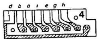
19 1 4 30 21 10 26
gn or gb sw br gr vi.
Part. no. 10720 50400

Semiconductor
IC
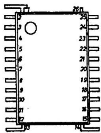
Part no. 10750 16001
D 2
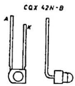
Part no. 10750 16008
T 1

Th 1
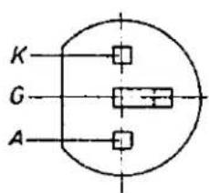
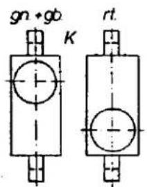
D1+D6 D3
Part no.
00363 25090
Part no.
00364 36090
Part no. 10720 16004 gn
10730 16005 gb
10720 16007 rt


MINOX
35PE
Circuit diagram - Biltzgerät
Schaltplan - Biltzgerät


PRECAUTIONS WHEN HANDLING THE MINOX 35 PE
The MINOX 35 PE incorporates a built-in electronic flash unit that operates internally at 350 V DC. Upon contact, this voltage causes considerable electrical shocks, so that certain precautionary measures have to be observed during repair and checking work.
The DC voltage is always present at the flash electrolytic capacitor if the unit has been switched on and the capacitor has not been completely discharged. When flashing normally with a 1.5 V battery or battery substitute inserted, renewed charging of the electrolytic capacitor starts immediately after triggering of the flash, with the result that a voltage has again been built up by the time the reflector is slid down.
Flashing can only cause almost complete discharge if, with the electrolytic capacitor in the charged condition, the battery or the battery substitute is removed, followed immediately by triggering of a flash. For those units which do not flash in such a case, e.g. due to a defect in the firing circuit, the electrolytic capacitor retains its full voltage.
If the unit is not used, the voltage on the electrolytic capacitor does not reduce completely to zero until after several hours or days. For this reason, it is necessary to ensure that the electrolytic capacitor is discharged before carrying out any work on the MINOX 35 PE.
The electrolytic capacitor must be discharged in different ways, according to the degree to which the camera has been stripped down.
I. Camera completely assembled with battery tube, camera electronics and connected flexes from the flash unit.
Discharge occurs between the negative contact of the camera battery internally in the battery tube and the negative contact of the flash unit battery with the aid of a special discharge cable.
To this end, first the adaptor must be inserted into the battery tube of the camera and then connected to the negative contact terminal of the flash battery. If this is down in the reverse order, accidental touching of the positive contact of the camera battery will cause irreparable damage to the camera electronics.

II. Camera partially stripped down, flash unit flexes are not connected.
If the unit is charged up again in this condition with the flexes not connected, discharge must take place by connecting the black flex to the negative contact of the flash unit battery at the bottom of the camera via a 1 k Ohm resistor.
Time for discharge: approx. 5 s.
Caution! Important note!
- Direct connection from the negative contact of the flash battery to the positive contact of the camera battery results in irreparable damage to the camera electronics.
- When working with a battery substitute for the camera battery, if the flash electrolytic capacitor is still charged, considerable electrical shocks are caused by simultaneously touching the negative contact of the flash battery and that of the battery substitute.
- During repair work on the camera electronics or the flash unit electronics, it is also necessary to make trials with the electrolytic capacitor charged up, e.g. in order to test the trigger circuit. When doing so, ensure that only one hand at any time touches the components of the camera electronics or of the flash unit electronics either directly or via a metal tool.
- In order to protect against possible residual voltages, the electrolytic capacitor should be discharged - as described under I. or II. above - prior to any work, if the charge condition of the electrolytic capacitor is not exactly known.
Functional description of the MINOX 35 PE built-in flash unit
1. Voltage transformer 3 V - 360 V

The power required for the flash is generated via a switching regulator.
After connecting the operating voltage, a collector current of about 2-3 A flows, initiated by the base bias ( R_21 ). Due to the transformer coupling, a positive voltage arises at the base point of the high-voltage winding. T_21 remains conducting until the collector winding is saturated. This phase can be referred to as the current flow phase. Upon saturation of the primary winding, the base voltage decreases and the transistor commences to block. The magnetic field in the transformer collapses and induces an AC voltage of about 350 - 370 V in the high-voltage winding. At the base point of the high-voltage winding, a negative potential arises, which blocks T_21 until induction has stopped (blocking phase). The sequence then recommences from the beginning. The oscillating frequency is about 16 kHz.
2. Trigger circuit
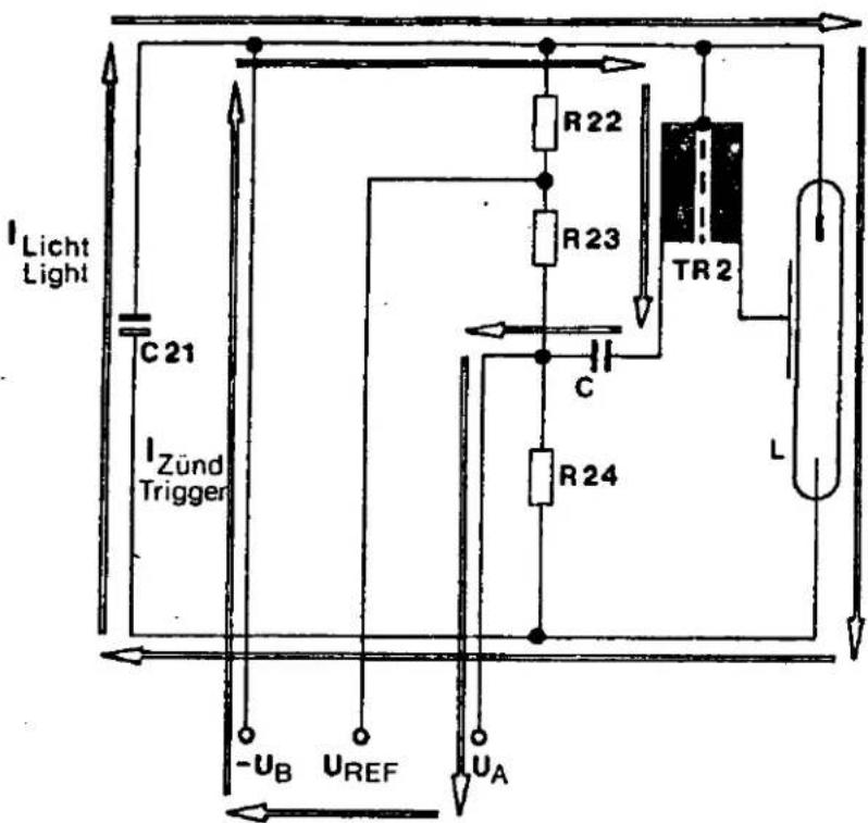
The energy stored in the trigger capacitor ( C_22 ) (charged up via R_22 , R_23 and R_24 ) is released instantaneously by a short-circuit of U_A to chassis earth (thyristor or switch).

The discharge current flows via the primary winding of the trigger transformer, and via C_22 back to the primary winding. The trigger transformer and the trigger capacitor thereby form a series oscillating circuit, the resonance frequency of which is about 800 kHz - 1 MHz. Thereby the resonance current induces the high voltage in the secondary winding (high-voltage winding). This ionizes the gas in the flash tube L, i.e. makes it conducting. Once the flash tube is triggered, then, with the current flow from C_21 via the flash tube and back again, light emission takes place until the current drops below the holding current of the flash tube.
3. Voltage generation by the light regulation circuit
If the flash tube is conducting (triggered), the high discharge current ( C_21 and L) causes a high negative pulse at C_21 . This pulse is integrated by the timing circuit consisting of R_26 and C_23 , so that a negative voltage component is present at Z diode D_22 , which is stabilized to the Zener voltage by the Z diode. This voltage supplies the light quantity regulation circuit.
In order for the light quantity regulation circuit to become active only due to its own flash, the somewhat more complicated solution is chosen via this circuit. Voltage for the Th_21 is tapped from the trigger voltage. This is supplied to C_26 and decoupled from the trigger voltage via diode D_23 . During the period of its own flash, the charge in C_26 is capable of triggering via Th_21 and the diode in the cathode-gate path to Th_22 .

4. Operation of the light quantity regulation circuit
Regulation of the light quantity is always downwards, i.e. it is only possible to regulate downwards from 100% of the light quantity in the direction 0%. In this case, the principle of parallel quenching is applied. Flash tube L is triggered, and upon attaining the correct light quantity, the residual charge in C_21 is dissipated via a charging capacitor C_21 in parallel to thyristor Th_22 , thus stopping light emission prematurely.
The sequence as a whole is as follows:
C_21 is charged to a value corresponding to the nominal power of the flash unit. If the flash tube is now triggered via the trigger circuit, the operating voltage for regulation of the light quantity appears at Z diode D_22 . If the photo-transistor registers light, a collector current flows which charges up C_24 . If the voltage at the gate of Th_21 exceeds the cathode voltage set with R_29 , Th_21 triggers. This in turn triggers Th_22 . This causes the residual charge in C_21 to be instantaneously dissipated and the flash tube extinguishes. C_24 is discharged via resistor R_25 which is connected in parallel to it, so that the conditions are identical for the next flash.
MINOX 35 PL/PE Testing Programme
- Basic Measurement
| B | L | R_i | ASA | LMm1xs | Remarks |
| A | D | 15 | 25 | 80 - 640 | |
| A | M | 15 | 25 | set same value asin previous measu-rement with R 10 |
- Filter Selection (from basic measurement)
| LMm1xs | F% | LMm1xs | F% | LMm1xs | F% | |||
| 80 | - 120 | 85 | 241 | - 260 | 60 | 381 | - 420 | 35 |
| 121 | - 160 | 80 | 261 | - 280 | 55 | 421 | - 460 | 30 |
| 161 | - 180 | 75 | 281 | - 320 | 50 | 461 | - 500 | 25 |
| 181 | - 200 | 70 | 321 | - 340 | 45 | 501 | - 540 | 20 |
| 201 | - 240 | 65 | 341 | - 380 | 40 | 541 | - 580 | 15 |
| 581 | - 620 | 7 | 621 | - 640 | 0 | |||
- Final Measurement
| B | L | R_i | ASA | LM m1x5 | Remarks | |
| A | D | 15 | 25 | 320 - 800 | after selection of neutral density filter recalibrate R 10 | |
| A | D | 15 | 100 | 128 - 192 | ||
| A | H | 8 | 200 | 40 - 120 | ||
| A | H | 15 | 200 | 60 - 160 | ||
| A | D | 15 | 400 | 20 - 60 | ||
| A | M | 15 | 400 | 20 - 60 | ||
| A | H | 15 | 400 | 28 - 100 | ||
| A | H | 15 | 25 | 400 - 1400 | ||
| A | H | 15 | 50 | 240 - 680 | ||
| A | H | 15 | 100 | 120 - 300 | ||
| A | H | 27 | 100 | 120 - 560 | ||
| A | M | 15 | 100 | 100 - 240 | ||
| T | M | 15 | 100 | 100 - 240 | ||
| 2x | M | 15 | 100 | 200 - 680 | ||
| ζ | M | 15 | 100 | 600 - 2400 | ||
| A | D | 15 | 400 →32 | D 3 flashes | ||
| A | D | 15 | 25 →64 | D 3 off | ||
| B | 27 | D 1 on | ||||
Legend
a) B = Mode of operation
A - Programme automatic
T - Timer switched on
2x - Couter light switched on
- Flash time
B • Battery check
b) L = Luminance (brightness). colour temperature = 4700 °K
| L | cd/m2 | ftImp | asb |
| H | 8000 | 2300 | 25000 |
| M | 1000 | 290 | 3125 |
| D | 125 | 36 | 390 |
c) R_i = Internal resistance of the voltage source at U = 5.4 V
d) LM = Light quantity at the film plane
e) F = Tone density of the compensation filter


- MINOX
- Ersatzteile
- Reparatur
- Spare Parts
- Repairs
- Pièces de rechange
- Réparation
- Repuestos
- Reparación
- PRECAUTIONS WHEN HANDLING THE MINOX 35 PE
- Voltage transformer 3 V - 360 V
- Trigger circuit
- Voltage generation by the light regulation circuit
- Operation of the light quantity regulation circuit
- The sequence as a whole is as follows:
- Legend
Marque : MINOX
Modèle : 35 PE
Catégorie : Appareil photo