M3 - Recepteur JBL - Notice d'utilisation et mode d'emploi gratuit
Retrouvez gratuitement la notice de l'appareil M3 JBL au format PDF.


| Type de produit | Récepteur stéréo AM/FM |
| Marque | JBL |
| Modèle | M3 |
| Dimensions (L x H x P) | 430 x 130 x 360 mm |
| Poids | 8,5 kg |
| Alimentation | Secteur 230 V, 50 Hz |
| Consommation électrique | 500 W (max) |
| Puissance de sortie | 2 x 100 W RMS sous 8 ohms |
| Impédance des enceintes | 8 ohms |
| Entrées audio | 4 entrées ligne (AUX, CD, etc.), 1 entrée phono, 1 entrée tuner |
| Sorties haut-parleurs | 2 paires (A et B) |
| Autres connecteurs | Sortie casque (6,35 mm), sortie préampli, borniers à vis |
| Tuner | AM/FM avec 30 présélections |
| Fonctions audio | Contrôle de tonalité (basses/aigus), balance, loudness |
| Matériau du châssis | Métal et plastique |
| Nettoyage et entretien | Chiffon doux et sec ; ne pas utiliser de produits liquides ou abrasifs |
| Sécurité | Ne pas exposer à l'humidité ; débrancher avant nettoyage ou en cas d'orage |
| Pièces détachées | Télécommande, fusible de rechange, antenne disponibles |
| Réparabilité | Confier à un technicien agréé JBL |
| Informations générales | Fabriqué en Chine ; garantie 2 ans |
FOIRE AUX QUESTIONS - M3 JBL
Questions des utilisateurs sur M3 JBL
0 question sur cet appareil. Repondez a celles que vous connaissez ou posez la votre.
Poser une nouvelle question sur cet appareil
Téléchargez la notice de votre Recepteur au format PDF gratuitement ! Retrouvez votre notice M3 - JBL et reprennez votre appareil électronique en main. Sur cette page sont publiés tous les documents nécessaires à l'utilisation de votre appareil M3 de la marque JBL.
MODE D'EMPLOI M3 JBL
M Series
JBL
A u t o m o t i v e
Power
A m p l i f i e r
RECEIVED
10APR'91
MOSAIC
| Models: | M 1 |
| M 2 | |
| M 3 | |
| M 4 |
Introduction
Congratulations on your purchase of a JBL M Series Automotive Power Amplifier! This amplifier has been built to meet the same rigorous standards of construction and performance that have been long established by our renowned professional power amplifiers.
This manual has been designed to make your JBL Automotive Power Amplifier installation and ownership as trouble-free as possible. Please read through this manual completely before attempting any installation steps and familiarize yourself with your new power amplifier.
Save Your Purchase Receipt
You will need your purchase receipt as proof of purchase for any and all warranty repairs and for insurance purposes. Keep your receipt, owner's manual, and packing materials in a safe location for possible future use.
Inspect for Shipping Damage
When unpacking your JBL Automotive Power Amplifier, inspect it thoroughly for shipping damage. Each unit leaves our factory only after thorough inspection, and any visible or concealed damage may have occurred in transit after the unit left our factory.
If there is damage: If you obtained your power amplifier from an authorized JBL dealer, it should be returned along with a copy of your purchase receipt to the dealer for inspection. Do not return any JBL products to Northridge, California, USA, without prior written authorization.
Additional Car Audio Equipment
JBL Automotive Power Amplifiers are compatible with most conventional car audio equipment. However, the amplifier's performance may be affected by your choice of speakers and electronics for use in your audio system.
Speakers
☐ The speakers chosen for your system must be able to safely handle the peak power rating of the amplifier.
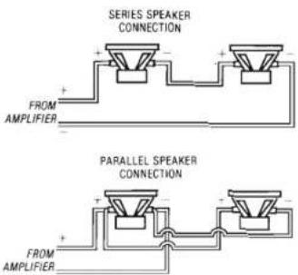
☐ When used in the stereo mode of operation, the amplifier can safely drive 2 ohm speaker loads or under conditions where there is only one speaker connected to each channel. If two speakers are connected in parallel to each channel, each speaker must have a nominal impedance of at least 4 ohms or more to ensure safe operation. Impedance loads of less than 2 ohms will cause the amplifier protection circuits to activate and interrupt normal operation.
☐ When used in the bridged mode of operation, the speakers chosen must have a nominal impedance of at least 4 ohms to ensure safe operation. Only one 4 ohm speaker (or the equivalent combination) should be connected to a bridged channel. If two speakers are connected in parallel to a bridged channel, each
speaker must have a nominal impedance of at least 8 ohms to ensure safe operation. In the bridged mode of operation, impedance loads of less than 4 ohms will cause the amplifier protection circuits to activate and interrupt normal operation.
☐ JBL Automotive Power Amplifiers must not be used with speakers designed with one of their input terminals connected to the speaker frame or chassis of the vehicle.
Electronics
☐ All JBL Automotive Power Amplifiers are equipped to accept the low level (preamp) outputs of almost any cassette/radio, CD player, preamp/equalizer, or electronic crossover. The input level control(s) on the amplifier can be used to match the sensitivity (level) of the particular electronic component sending the audio signal. More information on this subject can be found in the "Amplifier Operation" section of this manual.
☐ It is important that high quality electronics are used in the audio system to drive your JBL amplifier. Any component lacking a low level (preamp) output can be used only with the M1 amplifier, as it is equipped with a high level (speaker) input terminal. All other JBL Automotive Power Amplifiers have low level preamp inputs and must be used with equipment providing low level preamp outputs.
Pre-Installation Instructions
Your JBL Automotive Power Amplifier is a highly advanced electronic product that requires proper installation in order to operate at its maximum performance potential. JBL recommends that you have your power amplifier professionally installed by your authorized JBL dealer. This will ensure the use of proper installation techniques and materials, and will save much time and effort.
If you choose to perform your own installation, the following instructions will give you general direction toward making your purchase complete. Read the following information and precautions carefully. Failure to follow the stated precautions may result in personal injury and/or damage to the audio system or vehicle.
It is best to plan the complete audio installation before attempting any installation procedure. The routing of wires, power connections, amplifier placement, and signal interconnects must be planned in advance. As with any car audio installation, all work performed should be checked carefully before operating the audio system.
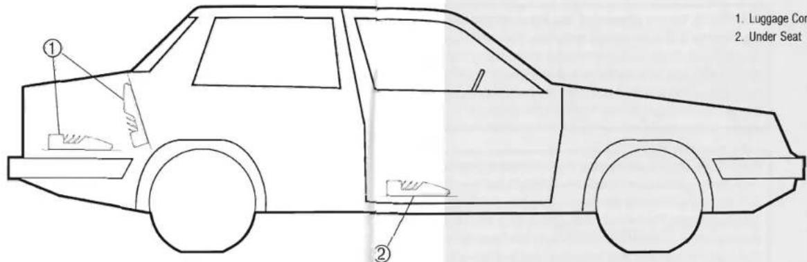
The placement of your JBL Automotive Power Amplifier within your vehicle will greatly affect the overall performance of your audio system. Depending on the amplifier's size, you may choose to mount your amplifier under a passenger seat or in the luggage compartment. Regardless of location, your JBL Automotive Power Amplifier must be mounted in an area where there is adequate air ventilation and no seat or body panel contact made with the amplifier's heat fins. Please refer to paragraphs 1-5 of the "General Amplifier Installation" section of this manual for further instruction.
General Amplifier Installation
NOTE: JBL Automotive Power Amplifiers must be installed only in vehicles that have a 12 volt negative ground electrical system. Connection to other types of automotive electrical systems may damage the amplifier and/or the vehicle's electrical system.
WARNING: Cutting, piercing or chafing fuel tanks, fuel lines or electrical wiring could result in a fire or long-term safety hazard. These items are often within close proximity to amplifiers mounted in the luggage compartment. Before any work is performed, check the area carefully and make sure there is adequate mounting screw depth available.
WARNING: Do not attempt to use the amplifier mounting plate as a drill or cutting template. Personal injury could result. Exercise extreme care when using power tools under any circumstances, and especially within the close confines of an automobile. Wear adequate eye protection, and follow instructions carefully.
CAUTION: Before attempting the installation, disconnect the negative terminal of the vehicle's battery. This will prevent accidental short circuits while performing the installation. Reconnect the battery only after the installation is complete and all wiring has been fully checked. Remember that batteries vent explosive gasses, so keep the area clear of any open flames when working around the battery.
Amplifier Mounting Precautions
JBL Automotive Power Amplifiers have a unique chassis design requiring specific mounting positions that will allow adequate heat dissipation from the heat fins. By following the positioning guidelines outlined below, the amplifier(s) will operate at maximum efficiency and the chance of amplifier shutdown will be greatly reduced.
IMPORTANT: Never mount any amplifier upside down.
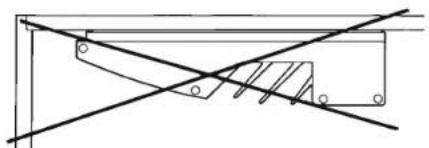
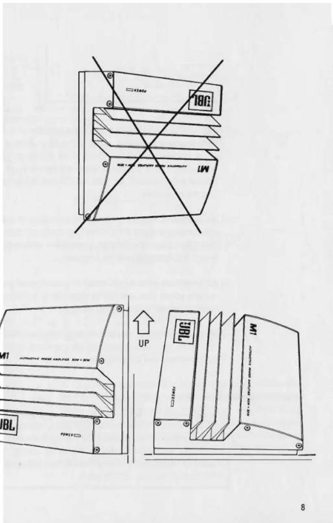

☐ All amplifiers must be mounted in a location of the vehicle where there is good air circulation. If the amplifier is installed in an area where there is poor air circulation (such as in a small storage compartment or behind a tight panel), an external fan and fan exhaust may be necessary.
☐ All amplifiers must be mounted in a location of the vehicle where there is no excessive shock or vibration that may loosen the mounting hardware. Mounting surface reinforcement may be necessary.
☐ All amplifiers must be mounted in a location of the vehicle where they will not be exposed to moisture, dirt, sand, extreme heat, or direct sunlight.
□ Whenever possible, use a mounting location that allows access to the amplifier's wiring connections, level adjustments, and power fuses.
Amplifier Mounting Instructions
NOTE: Make sure that all amplifier wiring will easily reach the connection points on the amplifier's rear panel with no wire or connector stress. All wiring should be routed away from possible damage resulting from heat or moving vehicle parts.

-
Use the metal amplifier mounting plate as a template and position the amplifier in the chosen location. Use a marking pen or a pencil to mark the four locations of the mounting screws. Drill the four holes for the plate mounting screws, making sure again that there is adequate screw clearance and no danger of damaging the fuel tank, fuel line, or electrical wires.
-
Place the amplifier mounting plate on the mounting surface and secure the plate tightly to the surface using all of the provided hardware.
- Position the amplifier over the mounting plate and place the front plate tab all the way into the mounting slot of the amplifier. Pivot the amplifier onto the mounting plate until the rear plate tab(s) are inserted completely into the amplifier chassis. Secure the amplifier to the mounting plate using the amplifier mounting screws attached to the amplifier chassis. Do not overtighten.
- Confirm adequate amplifier mounting by gently applying pressure in all directions. The amplifier should be tightly secured with no lateral movement. Confirm adequate wire lengths. Confirm access to controls and fuse(s).
Wiring
To ensure maximum performance and long-term reliability, proper wiring is critical at all stages of the installation. Wiring type, location, and execution will affect system performance and will usually determine overall sound quality and noise level.
CAUTION: Make sure the audio system is off when making any electrical connections. Failure to do so may damage the amplifier and/or audio system beyond repair.
☐ Run power and signal wires through existing holes, grommets, and wiring boots if possible. If no holes exist for running wires, protect wires from metal edges with rubber grommets or plastic insulators.
☐ If possible, do not place audio signal wires alongside any amplifier or vehicular power wires. Run signal wires and power wires down opposite sides of the vehicle. This will reduce the possibility of induced system noise.
☐ It may be necessary to use metal clips or plastic wire ties to route wire runs away from hot surfaces such as exhaust manifolds.
☐ To ensure long-term reliability, all bare wire-to-wire connections must be soldered and insulated with heat-shrink tubing or electrical tape. Never leave bare wire exposed under any circumstances.
□ Make sure seat and door movement is not hindered by any power, signal or speaker wires.
Connections
All JBL Automotive Power Amplifiers are equipped with quick-connect terminals for power, ground, remote, and speaker connections. They will handle up to 10AWG wire. Directions are as follows:
-
Strip away 15 mm (5/8") of the wire's insulation, twist the wire strands until thin, then insert into the appropriate terminal. If the wire proves to be too thick, un-twist the wire and remove some copper strands, re-twist, then re-insert into the terminal.
-
Using a small blade-type screwdriver, tighten the small screw directly over the terminal location until tight. Do not overtighten. Confirm a secure wire connection by pulling gently on the wire.

- Speaker Output Terminal
- Input Sensitivity Control
- Preamp Level Input Jacks
- Mono/Stereo Switch
- Power Supply Fuse
- Power and Ground Connection Terminal
- Mounting Screw
- Music Contour Switch
- Subwoofer Crossover Switches
- Speaker Level Input Terminal
CAUTION: To prevent electrical system damage or fire, the amplifier fuse must not be modified or bypassed. Use the same (or lower) fuse value if replacement is necessary. Do not replace a blown fuse with a fuse of a higher ampere rating. Repeated blowing of the power supply fuse indicates abnormal amplifier operation or improper installation, and repair to the system will be necessary.
Power Connections
☐ The "BATT" input terminal is for input directly from the positive terminal of the vehicle's battery.
☐ The "REM" input terminal is for a wire carrying the remote turn-on signal from the radio/cassette unit or CD player. When a +12 volt signal is applied to this input, the amplifier is enabled and will turn on if all other connections are correct and intact. When the +12 volt signal is removed, the amplifier will turn off.
☐ The "GND" input terminal is for a wire that is connected directly to a chassis ground point in the vehicle. It is important that the ground wire is of the same large gauge as the battery input wire and that a solid connection to a chassis grounding point is achieved. Upon locating an appropriate chassis grounding point, scrape all paint and primer coating from the area. Attach the wire (using a solder-on lug termination) to the treated area with a sheet metal screw and lock washer to ensure a solid connection.
Speaker Connections
NOTE: Proper bass response and stereo imaging is dependent on observing proper speaker polarity. Loudspeaker input terminals are normally marked in some fashion to identify the positive (+) and negative (-) terminal. Make sure that the positive (+) loudspeaker terminal is connected to the positive (+) amplifier terminal in all speaker-to-amplifier connections. Use high-quality JBL Optimum Performance Automotive Loudspeaker Cable for all speaker-to-amplifier connections to ensure proper system performance.
☐ M1, M2, and M3: The terminals marked "SPEAKER OUTPUT" are for speaker wire connections. Note the channel ("L" and "R") and polarity ("+" and "-") markings on the rear panel.
For stereo operation, positive and negative speaker leads connect straight to the "+" and "-" terminals of the amplifier for right and left channels. Make sure that the "MODE" switch on the rear panel is in the "STE-REO" position.
For bridged operation, the positive and negative speaker leads connect to the speaker output terminals labeled "BRIDGED." Make sure that the "MODE" switch on the rear panel is in the "MONO" position.
☐ M4 only: The terminals marked "SPEAKER OUTPUT" are for speaker wire connections. Note the channel ("L" and "R"), polarity (+" and "-") and separate "FRONT" and "REAR" output terminal markings on the rear panel.
For four channel operation, positive and negative speaker leads connect straight to the "+" and "-" terminals of the "FRONT" and "REAR" speaker output terminals. Make sure that the "MODE" switches on the rear panel are in the "STEREO" position for "FRONT" and "REAR" speaker outputs. Make sure that the "SUBWOOFER" switches on the rear panel are in the "FLAT" position.
For two channel operation, positive and negative speaker leads connect to the speaker output terminals labeled "BRIDGED". Connect the left speaker wires to the "FRONT" speaker terminal and the right speaker wires to the "REAR" speaker terminal. Make sure that the "MODE" switches on the rear panel are in the "MONO" position for "FRONT" and "REAR" speaker outputs. Make sure that the "SUBWOOFER" switches on the rear panel are in the "FLAT" position.
For three channel operation (with subwoofer), positive and negative speaker leads for two full range speakers connect straight to the "+" and "-" terminals of the "FRONT" speaker output terminals. Positive and negative speaker leads for a single subwoofer speaker
connect to the "REAR" speaker outputs labeled next to the "BRIDGED" designation. Make sure that the "MODE" switches on the rear panel are in the "STEREO" position for "FRONT" speaker outputs and in the "MONO" position for "REAR" speaker outputs. Make sure that the "SUBWOOFER" switches on the rear panel are in either the "50 Hz", "80 Hz", or "120 Hz" position.
Signal Connections
All JBL Automotive Power Amplifiers are equipped with high quality, gold plated RCA type signal input connections. Shielded audio interconnect cable must be used. If an additional electronic unit is equipped with another type of connector, an adaptor will be necessary to complete the signal connection to the amplifier. Consult your audio dealer to obtain the proper signal adaptor. Connect speaker leads as outlined in the "Speaker Connections" section of this manual.
☐ M1, M2, and M3: The RCA inputs marked "PREAMP LEVEL INPUTS" are for left channel ("L") and right channel ("R") low-level (preamp) signal inputs.
For stereo operation, insert the left channel signal input into the amplifier signal input terminal marked "L" (top input), and insert the right channel signal input into the amplifier signal input terminal marked "R" (bottom input).
For bridged mono operation, insert the mono signal input into the amplifier signal input terminal marked "L," which is the mono input.
☐ M4 only: The RCA inputs marked "PREAMP LEVEL INPUTS" are for left channel ("L") and right channel ("R") low-level (preamp) signal inputs. Note that the left side inputs are for signals intended for "FRONT" speakers and the right side inputs are for signals intended for "REAR" speakers. Depending on the desired mode of operation, the input layout may vary.
For four-channel stereo operation, insert the left channel signal input for the front speakers into the amplifier "FRONT" signal input terminal marked "L" (top left RCA input), and insert the right channel signal input for the front speakers into the amplifier "FRONT" signal input terminal marked "R" (bottom left RCA input). Repeat these steps for the rear signal input by using the "REAR" signal input terminals (RCA inputs on the right).
For bridged two-channel stereo operation, insert the left channel signal input into the amplifier "FRONT" signal input terminal marked "L" (top left RCA input), and insert the right channel input into the amplifier "REAR" signal input marked "L" (top right RCA input).
For three-channel operation with subwoofer, insert the full-range left channel input into the amplifier "FRONT" signal input terminal marked "L" (top left RCA input), and insert the full-range right channel input into the amplifier "FRONT" signal input marked "R" (bottom left RCA input). Insert the mono signal input into the amplifier "REAR" signal input terminal marked "L" (top right RCA input).
☐ M1 only: The input terminals marked "SPEAKER LEVEL INPUT" are provided for hookup from the speaker output of a high-level audio device (such as a self-powered cassette/radio). This will allow the M1 to be used as an amplifier "booster."
Insert the positive (+) left channel speaker output into the left ("L") terminal marked with the "+" polarity sign. Insert the negative (-) left channel speaker output into the left ("L") terminal with the "-" polarity sign. Repeat these steps for the right channel speaker output.
NOTE: Do not connect the output of an additional "equalizer/booster" to the M1 "SPEAKER LEVEL INPUT", as the circuits may differ greatly and cause unwanted noise and/or amplifier damage. Do not apply a signal to both "PREAMP LEVEL INPUT" and "SPEAKER LEVEL INPUT" at the same time.
Amplifier Operation
JBL Automotive Power Amplifiers have been designed for maximum system flexibility and can perform numerous functions. It is important, therefore, to carefully check the amplifier's mode of operation and loudspeaker wiring configuration before attempting to operate the amplifier.
☐ Recheck the power supply fuse for proper ampere rating and secure connection to the amplifier.
☐ Recheck the power, remote, and ground wiring for correct placement and secure connection to the amplifier.
☐ Recheck all speaker wiring for correct polarity and secure connection to the amplifier. Check for potential short circuits.
☐ Recheck all signal input wiring for correct channel orientation and secure connection to the amplifier.
☐ Recheck the "MODE" switch(es) for their proper settings.
NOTE: Before reconnecting the negative battery terminal, turn the "INPUT SENSITIVITY" switch(es) fully counter-clockwise to their least sensitive position and turn the audio system off. This will prevent any possible signal pulse or unwanted noise from reaching the loudspeakers in the case of system malfunction.
CAUTION: In the case of any unusual or unwanted noise existing in the audio system output upon initial operation, immediately remove power from the audio system and recheck all system connections.
Input Sensitivity
All JBL Automotive Power Amplifiers are equipped with a low-level (preamp) signal input sensitivity control. This control is useful for adjusting the audio signal level between the amplifier and other electronic components. The input sensitivity control should be set as low as possible to ensure a minimum of system noise.
☐ Adjustment: Start with the "INPUT SENSITIVITY" control(s) at minimum sensitivity (fully counter-clockwise). Turn the control(s) at minimum sensitivity (fully
counter-clockwise). Turn the control(s) clockwise approximately 1/8 of a turn. Adjust the volume control of the cassette/radio or CD player to a position that is approximately 3/4 full volume. If any additional electronic components are present in the system, adjust their output level(s) to maximum output. Adjust the amplifier's "INPUT SENSITIVITY" control until the system exhibits the first sign of distortion, then immediately turn the cassette/radio or CD player volume control down. More than one attempt may be necessary to properly adjust the input sensitivity of your amplifier. If problems arise, your authorized JBL dealer can assist in this procedure.
Music Contour™ Circuitry
M1 and M2 only: The "MUSIC CONTOUR" control on the rear panel of the M1 and M2 power amplifier is designed to provide better bass response in full-range amplifier applications. In the "OFF" position, the contour circuitry is disabled and the amplifier provides flat musical response. In the "ON" position, the contour circuitry alters the frequency balance of the music by boosting the low bass at 50 Hz by +6 dB (4 times the normal response), and reducing the upper midbass at 200 Hz by -3 dB (1/2 the normal response), while providing a subsonic filter at 20 Hz (conserves amplifier wattage during high power operation and reduces distortion).
NOTE: The Music Contour™ feature should be used only in full-range audio applications. This feature should not be used when the M1 or M2 amplifier is used in a multiple amplifier system with an electronic crossover. Undesirable musical response may result.

Turn-on Delay Circuitry
When installed properly, all JBL Automotive Power Amplifiers will turn on and off with the cassette/radio or CD player or by the vehicle's ignition switch. The amplifiers are designed with a delay circuit that will restrict the initial current surge (caused when the amplifier is turned on or off) from reaching the loudspeakers. This will eliminate the loud noises resulting from this current surge and will greatly reduce the possibility of loudspeaker damage.
The turn-on delay lasts between 1-3 seconds.
Amplifier Protection Circuitry
All JBL Automotive Power Amplifiers are equipped with sophisticated protection circuitry to prevent electrical damage to the amplifier as a result of miswiring, overheating, improper speaker loads or overvoltage.
☐ If your amplifier turns itself off regularly or does not work at all, there may be an installation problem or an abnormal electrical condition. Check all speaker and power wiring for short circuits and all speakers for impedance loads below 2 ohms in the stereo mode (below 4 ohms in bridged mode). Check power supply voltage at the amplifier "BATT" input for a normal value (between 11-17 volts).
☐ If your amplifier is extremely hot under normal operating conditions, the amplifier may not be in an area of the vehicle with adequate air ventilation. If the amplifier reaches a temperature of 80° C ( 176° F), the thermal overload protection circuit will turn the amplifier off. Once the amplifier surface temperature lowers, it will turn on again. Repeated thermal overload is an indication that the amplifier is mounted in a position or area of the vehicle that restricts adequate heat dissipation. Relocation of the amplifier is highly recommended to avoid further shutdown.
Power Consumption
All JBL Automotive Power Amplifiers are designed for maximum current draw efficiency, meaning that the amplifiers will not discharge the vehicle's battery when the vehicle is in operation with the engine running. Under normal conditions, the amplifiers will draw between 1-2 amperes of current at idle, 2-5 amperes of current during moderate operation, and as much as 25 amperes of peak, instantaneous current at high power, high volume operation. After even a short period of time, this current drain can possibly discharge the vehicle's battery to the point that the battery cannot start the vehicle. It is highly recommended that the audio system be operated with the engine running or for only brief periods of time with the engine off.
Fuse Replacement
If the fuse in your amplifier needs replacement, it must be replaced with the identical type of fuse and current value. Do not replace the fuse with a fuse rated for higher current values. Do not bypass or modify the fuse or fuse holder in any way. Serious damage to the amplifier and/or vehicle's electrical system may result. Repeated blowing of the power supply fuse indicates abnormal amplifier operation or improper installation.
Troubleshooting
If you had your amplifier installed by an audio dealer, return to the dealer's shop and demonstrate the problem to a technician for repair. If you installed the system yourself, use the following guidelines:
1. No power (LED does not light)
☐ Check all additional car audio equipment in the system. Check all battery connections and the "BATT" connection to the amplifier. Check all ground connections and the "GND" connection to the amplifier. Check the remote turn-on wire and the "REM" connection to the amplifier. Check for a blown fuse. Check for any wires shorting together or to chassis metal.
2. No sound (LED lights up)
☐ Check all signal connections. Check the "INPUT SENSITIVITY" control for full counter-clockwise position. Check operation status and output levels of any additional system electronics. Check for speaker wires shorting together or to chassis metal.
- Distorted sound at all volumes
☐ Check for loose signal connections. Check the "INPUT SENSITIVITY" control for full clockwise position. Check the output levels of any additional system electronics. Check "MODE" switches for correct position. Check speaker connections for correct polarity.
- Distorted sound at high volume only
☐ Check for loose loudspeaker mounting surfaces. Re-adjust the "INPUT SENSITIVITY" control of the amplifier. Inspect all loudspeakers for damage.
- Poor bass response
☐ Check speaker wiring for correct polarity. Check tone control or equalizer setting. If using M1 or M2, check Music Contour switch. If using M4, check subwoofer switch and frequency setting. Inspect loudspeakers for woofer cone damage.
- Poor high frequency response
☐ Check speaker wiring for correct polarity. Check tone control or equalizer setting. Inspect loudspeakers for tweeter damage.
- High frequency whine ("alternator noise")
☐ Check all grounding points in the system. It may be necessary to ground all electronic components to a single location on the vehicle chassis. If this fails to eliminate the noise, an external filter may be needed.
Important Notes
While JBL Automotive Power Amplifiers are built to high quality standards, care must be taken in operating the audio system.
☐ Do not attempt to overpower the audio system. Damage may result. This is true for momentary "bursts" as well as for extended periods of time.
☐ Do not operate the audio system into distortion. This will damage the loudspeakers and result in a costly repair procedure.
☐ Do not install audio system components in an unsafe area of the vehicle. If installed on a moving panel, extra care is needed to avoid system damage.
☐ If the audio system is malfunctioning in any way, JBL recommends an immediate repair of the system fault to avoid possible system damage.
☐ If any high-frequency whine (usually referred to as alternator whine) exists in the system, speaker damage may occur. JBL recommends prompt repair of the system. Consult your JBL autosound dealer for assistance.
☐ Due to variables created by frequent automotive design changes, JBL cannot guarantee that installation statements and technical information are complete, current, or applicable to any particular vehicle. Consult your JBL autosound dealer for up-to-date information before attempting any installation.
Service
Should your amplifier appear to require service, first make sure that the fault is with the amplifier. Often the problem is elsewhere, possibly in the loudspeakers, wiring, fusing, or radio/cassette unit.
If you determine that the amplifier needs service, contact the JBL dealer, agent, or authorized representative from whom the unit was purchased. Remember to retain the sales slip or invoice.
JBL continually engages in research related to product improvement. New materials, technologies, production and design techniques are often introduced into existing products without notice as an ongoing expression of this philosophy. For this reason, a current JBL product may differ in some respect from its published description, but will always equal or exceed the original design specifications unless otherwise stated.
Specifications
M1 Automotive Power Amplifier
| Power Output (stereo operation): | 30 watts RMS, 20 Hz-20,000 Hz |
| Power Output (bridged operation): | 80 watts RMS, 20 Hz-20,000 Hz100 watts peak music power(1kHz, 1% THD) |
| Total Harmonic Distortion | |
| stereo operation: | 0.05%, 20 Hz-20,000 Hz |
| bridged operation: | 0.05%, 20 Hz-20,000 Hz |
| Input Sensitivity (30 watt output, 4Ω): | 300 mV |
| Input Sensitivity Adjustment Range: | 300 mV-2.0V RMS |
| Signal-to-noise Ratio: | Better than 100 dB |
| Damping Factor (20 Hz-1 kHz): | Better than 100 |
| Slew Rate: | 20 V/μs |
| Input Impedance: | 20 kΩ |
| Idle Current: | <1 A |
| Dimensions (W x H x D): | 8" x 2-1/4" x 10"(200 mm x 57 mm x 254 mm) |
| Music ContourTM Circuit: | +6 dB boost @ 50 Hz-3 dB cut @ 200 Hz-12.5 dB cut @ 20 Hz |
M2 Automotive Power Amplifier
| Power Output (stereo operation): | 50 watts RMS, 20 Hz-20,000 Hz |
| Power Output (bridged operation): | 140 watts RMS, 20 Hz-20,000 Hz180 watts peak music power(1kHz, 1% THD) |
| Total Harmonic Distortion | |
| stereo operation: | 0.05%, 20 Hz-20,000 Hz |
| bridged operation: | 0.05%, 20 Hz-20,000 Hz |
| Input Sensitivity (50 watt output, 4Ω): | 300 mV |
| Input Sensitivity Adjustment Range: | 300 mV-2.0V RMS |
| Signal-to-noise Ratio: | Better than 100 dB |
| Damping Factor (20 Hz-1 kHz): | Better than 100 |
| Slew Rate: | 20 V/μs |
| input Impedance: | 20 kΩ |
| Idle Current: | <1 A |
| Dimensions (W x H x D): | 11" x 2-1/4" x 10"(278 mm x 57 mm x 254 mm) |
| Music ContourTM Circuit: | +6 dB boost @ 50 Hz-3 dB cut @ 200 Hz-12.5 dB cut @ 20 Hz |
M3 Automotive Power Amplifier
| Power Output (stereo operation): | 100 watts RMS, 20 Hz-20,000 Hz |
| Power Output (bridged operation): | 250 watts RMS, 20 Hz-20,000 Hz300 watts peak music power |
| Total Harmonic Distortion | |
| stereo operation: | 0.05%, 20 Hz-20,000 Hz |
| bridged operation: | 0.05%, 20 Hz-20,000 Hz |
| Input Sensitivity (100 watt output, 4Ω): | 300 mV |
| Input Sensitivity Adjustment Range: | 300 mV-2.0V RMS |
| Signal-to-noise Ratio: | Better than 105 dB |
| Damping Factor (20 Hz-1 kHz): | Better than 100 |
| Slew Rate: | 20 V/μs |
| Input Impedance: | 20 kΩ |
| Idle Current: | <2 A |
| Dimensions (W x H x D): | 14" x 2-1/4" x 10"(355 mm x 57 mm x 254 mm) |
M4 Automotive Power Amplifier
| Power Output (4-channel operation): | 40 watts RMS, 20 Hz-20,000 Hz |
| Power Output (2-channel operation): | 100 watts RMS, 20 Hz-20,000 Hz |
| Power Output (3-channel operation): | 40 watts RMS X 2 |
| 100 watts RMS X 1 | |
| Total Harmonic Distortion | |
| 4-channel operation: | 0.05%, 20 Hz-20,000 Hz |
| 2-channel operation: | 0.05%, 20 Hz-20,000 Hz |
| Input Sensitivity (40 watt output, 4Ω): | 300 mV |
| Input Sensitivity Adjustment Range: | 300 mV-2.0V RMS |
| Signal-to-noise Ratio: | Better than 100 dB |
| Damping Factor (20 Hz-1 kHz): | Better than 100 |
| Slew Rate: | 20 V/μs |
| Input Impedance: | 20 kΩ |
| Idle Current: | <2A |
| Subwoofer Crossover | |
| Frequencies: | 50 Hz, 80 Hz, 120 Hz |
| Dimensions (W x H x D): | 14" x 2-1/4" x 10" |
| 355 mm x 57 mm x 254 mm | |
JBL
JBL Incorporated
8500 Balboa Boulevard
Northridge, California 91329
- INTRODUCTION
- SAVE YOUR PURCHASE RECEIPT
- INSPECT FOR SHIPPING DAMAGE
- ADDITIONAL CAR AUDIO EQUIPMENT
- SPEAKERS
- ELECTRONICS
- PRE-INSTALLATION INSTRUCTIONS
- GENERAL AMPLIFIER INSTALLATION
- AMPLIFIER MOUNTING PRECAUTIONS
- AMPLIFIER MOUNTING INSTRUCTIONS
- WIRING
- CONNECTIONS
- POWER CONNECTIONS
- SPEAKER CONNECTIONS
- SIGNAL CONNECTIONS
- AMPLIFIER OPERATION
- INPUT SENSITIVITY
- MUSIC CONTOUR™ CIRCUITRY
- TURN-ON DELAY CIRCUITRY
- AMPLIFIER PROTECTION CIRCUITRY
- POWER CONSUMPTION
- FUSE REPLACEMENT
- TROUBLESHOOTING
- NO POWER (LED DOES NOT LIGHT)
- NO SOUND (LED LIGHTS UP)
- IMPORTANT NOTES
- SERVICE
Marque : JBL
Modèle : M3
Catégorie : Recepteur