CA-HM-NI.001 - Autoradio PIONEER - Notice d'utilisation et mode d'emploi gratuit
Retrouvez gratuitement la notice de l'appareil CA-HM-NI.001 PIONEER au format PDF.


| Type de produit | Appareil électronique |
| Marque | Pioneer |
| Modèle | CA-HM-NI.001 |
| Dimensions (L x l x h) | 200 x 150 x 50 mm |
| Poids | 0,5 kg |
| Alimentation | Secteur 230 V ~ 50 Hz |
| Consommation électrique | 15 W |
| Fonctions principales | Lecture audio, réglage du volume, entrée auxiliaire |
| Matériau du boîtier | Plastique ABS |
| Température de fonctionnement | 0 °C à 40 °C |
| Entretien et nettoyage | Essuyer avec un chiffon doux et sec. Ne pas utiliser de produits abrasifs. |
| Sécurité | Débrancher avant tout nettoyage. Ne pas exposer à l'eau ou à l'humidité. |
| Pièces détachées | Disponibles auprès du service après-vente Pioneer |
| Réparabilité | Indice de réparabilité : 8/10 (estimation) |
| Garantie | 2 ans (selon législation) |
| Contenu de l'emballage | Appareil, câble d'alimentation, manuel d'utilisation |
| Pays d'origine | Japon (estimation) |
| Classe énergétique | Non applicable |
FOIRE AUX QUESTIONS - CA-HM-NI.001 PIONEER
Questions des utilisateurs sur CA-HM-NI.001 PIONEER
0 question sur cet appareil. Repondez a celles que vous connaissez ou posez la votre.
Poser une nouvelle question sur cet appareil
Téléchargez la notice de votre Autoradio au format PDF gratuitement ! Retrouvez votre notice CA-HM-NI.001 - PIONEER et reprennez votre appareil électronique en main. Sur cette page sont publiés tous les documents nécessaires à l'utilisation de votre appareil CA-HM-NI.001 de la marque PIONEER.
MODE D'EMPLOI CA-HM-NI.001 PIONEER
APPLICATIONS Nissan Murano 2009
(Without Bose Audio)
CA-HM-NI.001
KIT FEATURES
• DIN Mount Radio Provision with Pocket
• ISO Mount Radio Provision with Pocket
• Double DIN Radio Provision
- Stacked ISO Mount Units Provision
• Painted To Match OEM Finish

natural_image
Close-up of a car air conditioner unit with digital display and control panel (no visible text or symbols)KIT COMPONENTS
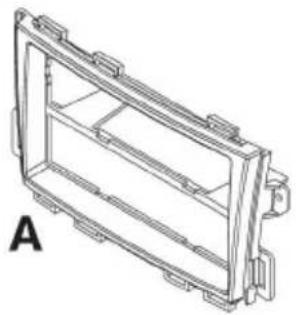
A) Radio Housing • B) ISO Brackets • C) ISO Trim Plate • D) Double DIN Brackets E) Double DIN Trim Plate • F) Pocket
natural_image
Technical line drawing of a rectangular mechanical housing or enclosure with mounting brackets (no text or symbols)
natural_image
Technical line drawing of two mechanical bracket components labeled B (no text or symbols on the brackets)
natural_image
Technical line drawing of a rectangular frame with four corner slots, labeled 'C' (no text or symbols on the diagram itself)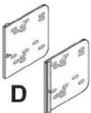
natural_image
Two identical rectangular panels with patterned surfaces, labeled 'D' at the bottom (no text or symbols on panels)
natural_image
Simple line drawing of a rectangular frame with mounting holes and a label 'E' on the left (no other text or symbols)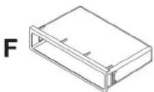
natural_image
Isometric line drawing of a rectangular electronic component with a labeled section 'F' (no text or symbols on the object itself)TOOLS REQUIRED:
Small Flat Blade Screwdriver or Panel Removal Tool
• Phillips Screwdriver
TABLE OF CONTENTS
- Dash Disassembly
- Nissan Murano 2009 (Without Bose Audio)......1, 2
- Kit Assembly:
- DIN Mount Radio Provision with Pocket......3
- ISO Mount Radio Provision with Pocket ....4
- Double DIN Radio Provision ....5
- Stacked ISO Mount Units Provision....5
- Final Assembly ......6
*Note:
Refer also to the instructions included with the aftermarket radio.
NISSAN MURANO 2009
1 Disconnect the negative battery terminal to prevent an accidental short circuit.
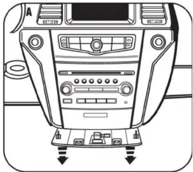
2 Unclip trim panel at bottom center of dash. (Figure A)
3 Remove (1) Phillips screw from bottom of each side trim panel. Unclip and remove the side trim panels. (Figure B)
4 Remove (3) Phillips screws securing the climate control then unclip, unplug and remove it from the sub dash. (Figure C)
Continued on next page.
natural_image
Line drawing of a car dashboard with control panel and buttons (no text or symbols)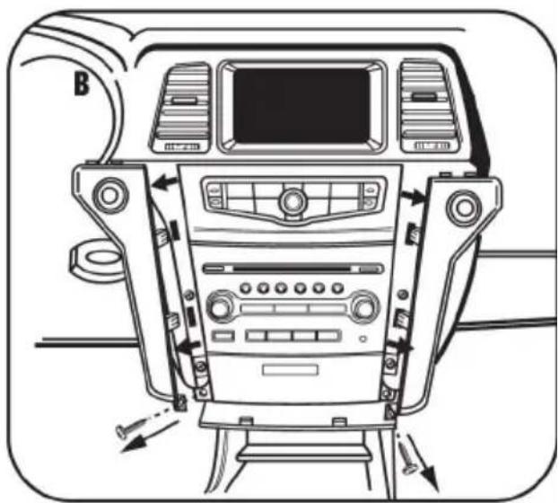
natural_image
Interior view of a car dashboard with air conditioners and control panel (no text or symbols visible)
NISSAN MURANO 2009
5 Remove (2) Phillips screws from the panel below the radio (containing the passenger air bag light) then unclip, unplug and remove the panel. (Figure D)
6 Remove (6) Phillips screws securing the radio to the sub dash. Unplug and remove radio. (Figure E)
Continue to kit assembly.

natural_image
Top-down line drawing of a car dashboard with control panel and air vent (no text or symbols)
DIN MOUNT RADIO PROVISION WITH POCKET
*Note: Refer also to the instructions included with the aftermarket radio.
1 Slide the DIN cage into the radio housing and secure by bending the metal locking tabs down. (Figure A)
2 Slide the aftermarket radio into the cage until it snaps into place. (Figure B)
3 Snap the pocket into the radio housing. (Figure C)
Continue to final assembly.

natural_image
Line drawing of a hand inserting a component into a device housing (no text or symbols)
natural_image
Technical line drawing of an electronic device with labeled ports and connectors (no text or symbols present)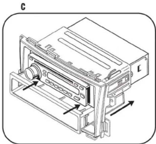
natural_image
Technical line drawing of a computer drive unit with labeled ports and directional arrows (no text or symbols beyond labels)ISO MOUNT RADIO PROVISION WITH POCKET
*Note: Refer also to the instructions included with the aftermarket radio.
1 Mount the ISO Brackets to the radio using the screws supplied with the radio. (Figure A)
2 Slide the radio into the radio housing until it snaps into place. (Figure B)
3 Snap the Trim plate onto the front of the Radio Housing. (Figure B)
4 Snap the pocket into the radio housing. (Figure C)
Continue to final assembly.

natural_image
Illustration of a hand inserting a USB into a device housing (no text or symbols visible)

natural_image
Technical line drawing of a computer drive unit with mounting bracket and control panel (no text or symbols)DOUBLE DIN RADIO PROVISION
STACKED ISO MOUNT UNITS PROVISION
*Note: Refer also to the instructions included with the aftermarket radio.
1 Cut and remove the center bar from the radio housing. (Figure A)
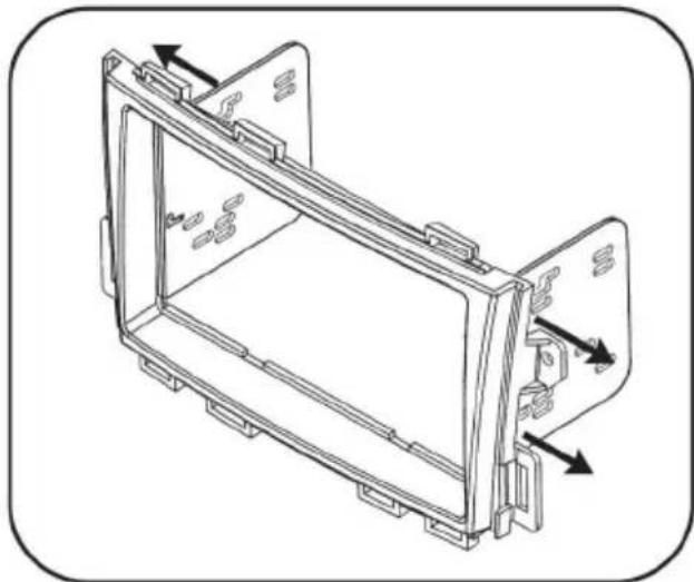
2 Snap the Double DIN brackets to the inside edge of the radio housing. (Figure B)
3 Slide the Double DIN or ISO mount unit(s) into the bracket/radio housing assembly and secure the unit(s) to the assembly using the screws supplied with the unit(s). (Figure C)
4 Snap the Double DIN trim plate onto the front of the radio/housing. (Figure C)
Continue to final assembly.
A

natural_image
Line drawing of a hand holding a mechanical component, showing a bracket and adjustment mechanism (no text or symbols)B
natural_image
Technical line drawing of a car front panel with mounting brackets and directional arrows indicating movement (no text or symbols)C

natural_image
Technical line drawing of a mechanical device with internal components and directional arrows indicating assembly (no text or symbols)Marque : PIONEER
Modèle : CA-HM-NI.001
Catégorie : Autoradio