
CA-IW-ISU.002 - Accessoire électronique PIONEER - Notice d'utilisation et mode d'emploi gratuit
Retrouvez gratuitement la notice de l'appareil CA-IW-ISU.002 PIONEER au format PDF.


| Type de produit | Enceinte encastrable (in-wall) |
| Marque | PIONEER |
| Modèle | CA-IW-ISU.002 |
| Dimensions (L x H x P) | 250 x 150 x 80 mm |
| Poids | 1.2 kg |
| Puissance admissible (RMS) | 50 W |
| Impédance nominale | 8 ohms |
| Réponse en fréquence | 60 Hz - 20 kHz |
| Sensibilité | 88 dB (1W/1m) |
| Matériau du cône | Polypropylène |
| Tweeter | Dôme souple de 25 mm |
| Alimentation | Passive, via amplificateur externe |
| Utilisation | Encastrement mural |
| Fixation | Patères de montage incluses |
| Finition | Blanc |
| Grille de protection | Incluse, aimantée |
| Gabarit de découpe | Inclus |
| Entretien | Nettoyage avec un chiffon doux sec |
| Sécurité | Ne pas exposer à l'humidité ou températures extrêmes |
| Garantie | 2 ans |
| Réparabilité | Pièces détachées disponibles sur demande |
FOIRE AUX QUESTIONS - CA-IW-ISU.002 PIONEER
Questions des utilisateurs sur CA-IW-ISU.002 PIONEER
0 question sur cet appareil. Repondez a celles que vous connaissez ou posez la votre.
Poser une nouvelle question sur cet appareil
Téléchargez la notice de votre Accessoire électronique au format PDF gratuitement ! Retrouvez votre notice CA-IW-ISU.002 - PIONEER et reprennez votre appareil électronique en main. Sur cette page sont publiés tous les documents nécessaires à l'utilisation de votre appareil CA-IW-ISU.002 de la marque PIONEER.
MODE D'EMPLOI CA-IW-ISU.002 PIONEER
USB and Jack 3,5mm replacement PCB installation kit for :
ISUZU
Model: D-Max;
Year: 2021>
Kit content: USB and Jack 3,5mm replacement PCB and Plastic cover
Customer code: CA-IW-ISU.002

natural_image
Coiled black cable with two USB connectors and a small device labeled 'USB AUX' (no text or symbols on the cable itself)03/2021 ALL RIGHTS RESERVED. Technical changes possible. No liability for misprints R0
All installation work must be performed by a qualified professional installer only. The manufacturer / dealer is not liable for any kind of incidental or indirect damages.
1

- Remove the plastic cover circled in Red.
2

natural_image
Close-up of a black USB cable connector with green and yellow wires, shown from an open rear panel (no text or symbols visible)2 Connect the White connector to PCB as shown in the picture.
3
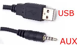
3 Plug the connector of the harness and do all connections on radio side. Insert the USB and 3,5 mm Jack replacement panel into the hole left by the OEM part. Please note that USB connector must be always connected to guarantee the proper function of the system.
4

4 This is the final result.
ATTENTION!
IF YOUR VEHICLE IS EQUIPPED WITH THE SWITCH PANEL SHOWN IN THE PICTURE 5A, INSTALL THE USB/AUX PCB IN THE GLOVE COMPARTMENT AS SHOWN IN THE PICTURE 5B.
5A

5B

natural_image
Interior view of a metallic storage or shelf with a small electronic device on top (no visible text or symbols)Marque : PIONEER
Modèle : CA-IW-ISU.002
Catégorie : Accessoire électronique