SIMRAD

Outboard Pilot - Électronique marine SIMRAD - Notice d'utilisation et mode d'emploi gratuit

Retrouvez gratuitement la notice de l'appareil Outboard Pilot SIMRAD au format PDF.

📄 2 pages Français FR Télécharger 💬 Question IA 10 questions ⚙️ Specs
Notice SIMRAD Outboard Pilot - page 1
Choisissez votre langue et indiquez votre email : nous vous enverrons une version traduite specifiquement.
Type de produit Pilote automatique pour moteur hors-bord
Marque Simrad
Modèle Outboard Pilot
Dimensions (unité de commande) 150 x 100 x 50 mm
Poids 1,5 kg
Alimentation 12 V CC
Consommation électrique Moins de 2 A
Fonctions principales Maintien du cap, navigation vers waypoint, compensation du vent et du courant
Étanchéité IPX6
Matériau du boîtier Plastique renforcé
Type d'installation Montage sur tableau arrière ou console
Entretien et nettoyage Nettoyer avec un chiffon humide, éviter les produits abrasifs
Sécurité Désengagement automatique en cas de surcharge, bouton d'arrêt d'urgence
Pièces détachées disponibles Moteur d'orientation, câbles, fusibles, capteurs
Réparabilité Réparable par un technicien agréé, pièces disponibles

FOIRE AUX QUESTIONS - Outboard Pilot SIMRAD

Comment installer le pilote automatique Simrad Outboard Pilot ?
L'installation nécessite de monter l'unité de commande sur le tableau arrière ou la console, de connecter le moteur d'orientation au safran du moteur hors-bord, et de brancher l'alimentation 12 V. Consultez le manuel pour les schémas détaillés.
Comment calibrer le compas du Outboard Pilot ?
Accédez au menu de calibration via l'écran de commande, suivez les instructions pour effectuer une rotation complète du bateau à basse vitesse. La calibration prend environ 2 minutes.
Que faire si le pilote ne maintient pas le cap ?
Vérifiez d'abord que le compas est correctement calibré. Ensuite, assurez-vous que le moteur d'orientation est bien fixé et que les câbles ne sont pas endommagés. Un déséquilibre du bateau peut aussi affecter le cap.
Le pilote est-il compatible avec tous les moteurs hors-bord ?
Le Simrad Outboard Pilot est conçu pour la plupart des moteurs hors-bord jusqu'à 300 CV. Vérifiez la compatibilité avec votre modèle spécifique dans le manuel ou auprès du fabricant.
Comment nettoyer et entretenir le Outboard Pilot ?
Nettoyez l'unité de commande avec un chiffon humide et doux. Évitez les produits chimiques agressifs. Vérifiez régulièrement les connexions électriques et le câblage pour éviter la corrosion.
Quelle est la consommation électrique du pilote automatique ?
La consommation typique est inférieure à 2 A sous 12 V, mais elle peut atteindre 5 A en fonctionnement intense. Utilisez un circuit dédié avec un fusible de 5 A recommandé.
Le pilote dispose-t-il d'une fonction d'arrêt d'urgence ?
Oui, le Outboard Pilot est équipé d'un bouton d'arrêt d'urgence situé sur l'unité de commande. Appuyez dessus pour désactiver immédiatement le pilotage automatique.
Comment mettre à jour le logiciel du Outboard Pilot ?
Les mises à jour se font via une carte SD ou un câble USB, en téléchargeant le firmware sur le site Simrad. Consultez le manuel pour la procédure exacte.
Quelles sont les dimensions du boîtier de commande ?
Le boîtier de commande mesure environ 150 mm de large, 100 mm de haut et 50 mm de profondeur. Pèse environ 1,5 kg.
Où trouver des pièces détachées pour le Outboard Pilot ?
Les pièces détachées sont disponibles auprès des revendeurs agréés Simrad ou en ligne. Les pièces courantes incluent le moteur d'orientation, les câbles, les fusibles et les capteurs.

Questions des utilisateurs sur Outboard Pilot SIMRAD

0 question sur cet appareil. Repondez a celles que vous connaissez ou posez la votre.

Poser une nouvelle question sur cet appareil

L'email reste privé : il sert seulement à vous prévenir si quelqu'un répond à votre question.

Aucune question pour l'instant. Soyez le premier à en poser une.

Téléchargez la notice de votre Électronique marine au format PDF gratuitement ! Retrouvez votre notice Outboard Pilot - SIMRAD et reprennez votre appareil électronique en main. Sur cette page sont publiés tous les documents nécessaires à l'utilisation de votre appareil Outboard Pilot de la marque SIMRAD.

MODE D'EMPLOI Outboard Pilot SIMRAD

LOWRANCE SIMRAD Outboard pilot, Cable steer pack Installation Guide ENGLISH * 9 8 8 - 1 0 7 1 8 - 0 0 4 * www.simrad-yachting.com | www.lowrance.com

Technical specifications PLANNING: Dimensions NAC-1 Operating temperature -25°C to +55°C (13°F to 131°F) Protection Splashproof, IPx5 Weight 0.6 kg (1.3 lbs) Power supply/Load 9-16 V DC/140 mA + drive unit load Performance Drive: 8 A coeff., 16 A for 1 s Point-TAP Operating temperature -25°C to +60°C (13°F to 140°F) Protection Waisertight, IPx7 Weight 0.14 kg (0.31 lbs) Power supply/Load 9-16 V DC/

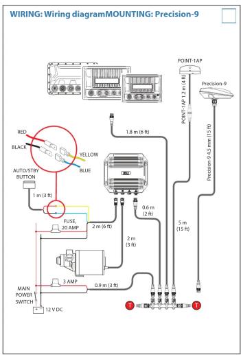
PLANNING: Tools needed Screwdriver Drill Wrench Tools to connect power cables to the battery. PLANNING: Cable lengths Refer to Wiring diagram (point 15) to find the various cable lengths.

119 mm (4.60") 36 mm (1.42") 133 mm (5.23") 119 mm (4.69) 126 mm (4.96") 120 mm (4.96) 72 mm (2.83) 204 mm (8.1) 183 mm (7.2) 91 mm (3.6) 109 mm (0.63) 57 mm (9.2) 190 mm (7.5) 180 mm (7.1) 155 mm (6.1) 76 mm (3.0) 100 mm (4.0) 85 mm (3.4) 85 mm (3.4)

PLANNING: Point-1AP and Precision-9 Compass, Mounting location Point-1AP Electromagnetic Interference Precision-9 Point-1AP and Precision-9 The compasses contain a magnetic heading sensor and should not be mounted close to any potential magnetic source, and as close to the vessel's centre of roll and pitch as possible. Refer to technical specifications. Potential sources for magnetic/electromagnetic interference include: • Electrical Motors/Magnets/Moving Metal items • Outboard Engines • High current electrical sources such as main power cables, batteries, distribution panels etc. The Point-1AP compass also comes with a GPS antenna and should be mounted as far as possible away from disturbing magnetic/ electromagnetic interferences.

Compatibility information The drive unit either replaces or is used in conjunction with common brands of mechanical rotary and rack and pinion steering helm units. The drive is based on the Morse 290 rotary helm unit and accepts Morse 304411 and Teleflex SSC52 rotary cables without modification. If the boat is fitted with any of the following systems: Teleflex Safe T or Teleflex Big T Uflex T71 Uflex T73NR or Uflex T81 A cable adapter must be fitted to the cable before installing the drive. If the boat has a rack and pinion type steering system (or other brands of rotary system), the drive can be used, but the steering cable must also be replaced with a Morse 304411 or Teleflex SSC52. The drive is designed to produce a maximum cable push/pull of 136 kg, which makes it suitable for the vast majority of cable steered boats. However, some boats fitted with push-pull cable steering systems have very stiff steering or steering which is heavily loaded in one direction due to hull design and engine considerations. Generally speaking, the drive will steer boats that do not require more than a 7 kg force on the rim of a 35 cm diameter steering wheel to hold a course, this equals 1.2 kgm of torque. If the steering wheel input torque exceeds this figure it is recommended that a hydraulic linear actuator drive system is used.

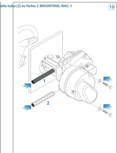
Remove steering cable (1) and cable tube (2) from existing manual helm 1 2

Remove existing manual helm from dashboard 8

Install Helm-1 to dashboard Install steering cable (1) and ca

Hem-1 MOUNTING: NAC-1 1 2

Helm-1, Rudder feedback calibration 1 2 3 4 1. Remove the rudder feedback sensor from the drive unit 2. Centre the steering 3. Align the 2 red dots 4. Fit the rudder position sensor to the drive unit. 11

Technical diagram showing installation of a device with labeled ports and three schematic diagrams indicating status indicators.

Without bracket With bracket 1 2 3 For more details about mounting Precision-9, refer to the Precision-9 Mounting Template and Installation Guide. available for download on: www.simrad-yachting.com www.lowrance.com www.bandg.com

MOUNTING: Point-1AP A 2 1° Ø 19 mm (0.75°) 2° Ø 3 mm (0.12°) Note the mounting direction! C B 14

WIRING: Wiring diagramMOUNTING: Precision-9 RED BLACK AUTO/STRY BUTTON 1 m (3 ft) FUSE 20 AMP 2 m (6 ft) BLUE YELLOW 1.8 m (6 ft) 0.6 m (2 ft) 2 m (3 ft) MAIN POWER SWITCH 3 AMP 0.9 m (3 ft) 12 V DC POINT-1AP 1.2 m (4 ft) Precision-9 5 m (15 ft) 3 100Ω 10Ω 10Ω 10Ω 10Ω 10Ω 10Ω 10Ω 10Ω 10Ω 10Ω 10Ω 10Ω 10Ω 10Ω 10Ω 10Ω 10Ω 10Ω 10Ω 10Ω 10Ω 10Ω 10Ω 10Ω 10Ω 10Ω

Configuration and reference Refer to your Autopilot controller's documentation for setup instructions. Straight Shaft Helm Drive Helm-1 drive manual For more details about Helm-1, refer to the Straight Shaft Helm Drive manual, available for download on: www.simrad-yachting.com Compliance Statements The Outboard pilot, Cable steer pack: • Complies with CE under EMC directive 2004/108/EC • Complies with the requirements of level 2 devices of the Radiocommunications (Electromagnetic Compatibility) standard The relevant Declaration of Conformity is available on the following websites under model documentation section: www.simrad-yachting.com www.lowrance.com

Assistant notice
Powered by Anthropic
En attente de votre message
Informations produit

Marque : SIMRAD

Modèle : Outboard Pilot

Catégorie : Électronique marine