NAC-2 - Électronique marine SIMRAD - Notice d'utilisation et mode d'emploi gratuit
Retrouvez gratuitement la notice de l'appareil NAC-2 SIMRAD au format PDF.


| Type de produit | Calculateur de pilote automatique pour bateau |
| Marque | Simrad |
| Modèle | NAC-2 |
| Dimensions (L x l x h) | 200 x 150 x 50 mm |
| Poids | 1,2 kg |
| Alimentation | 12 V CC (10-16 V) |
| Consommation électrique | Moins de 2 A typique |
| Fonctions principales | Contrôle du pilote automatique, interface NMEA 2000, sortie moteur, support des capteurs de cap et GPS |
| Connectivité | NMEA 2000, RS232, contacts secs |
| Protection | Indice IP54 (boîtier étanche) |
| Température de fonctionnement | -10°C à +55°C |
| Entretien et nettoyage | Nettoyer avec un chiffon doux et sec. Éviter les produits chimiques et l'eau sous pression. |
| Sécurité | Respecter les normes électriques marines. Couper l'alimentation avant toute intervention. |
| Pièces détachées et réparabilité | Contacter un centre de service agréé Simrad pour les réparations et pièces. |
| Garantie | 2 ans (selon conditions du fabricant) |
| Informations générales | Conçu pour une utilisation en milieu marin. Compatible avec les commandes Simrad et les capteurs externes. |
FOIRE AUX QUESTIONS - NAC-2 SIMRAD
Questions des utilisateurs sur NAC-2 SIMRAD
0 question sur cet appareil. Repondez a celles que vous connaissez ou posez la votre.
Poser une nouvelle question sur cet appareil
Téléchargez la notice de votre Électronique marine au format PDF gratuitement ! Retrouvez votre notice NAC-2 - SIMRAD et reprennez votre appareil électronique en main. Sur cette page sont publiés tous les documents nécessaires à l'utilisation de votre appareil NAC-2 de la marque SIMRAD.
MODE D'EMPLOI NAC-2 SIMRAD
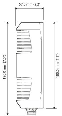
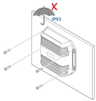
Dimensions Mounting

SIMRAD®
B&G
NAC ^TM -2
INSTALLATION GUIDE

natural_image
Line drawing of a rectangular electronic device with three ports and ventilation slots (no text or symbols)System wiring example

flowchart
graph LR
    A["NAC™-2"] -->|12/24V DC| B["Power"]
    A -->|12/24V DC| C["Drive Unit"]
    C --> D["Rudder FEEDBACK"]
    D --> E["AUTOPILOT CONTROLLER"]
    E --> F["MPD"]
    F --> G["12/24V DC"]
    G --> H["GPS SENSOR"]
    H --> I["COMPASS"]
    I --> J["12V DC"]
    J --> K["Drive cable"]
    style A fill:#f9f,stroke:#333
    style B fill:#ccf,stroke:#333
    style C fill:#cfc,stroke:#333
    style D fill:#fcc,stroke:#333
    style E fill:#cff,stroke:#333
    style F fill:#ffc,stroke:#333
    style G fill:#cfc,stroke:#333
    style H fill:#fcc,stroke:#333
    style I fill:#cfc,stroke:#333
    style J fill:#fcc,stroke:#333
    style K fill:#cfc,stroke:#333

For setup instructions, commissioning guide, product manuals, technical specifications, certificates and declarations, refer to the product website:
www.simrad-yachting.com
www.bandg.com
Trademark
®Reg. U.S. Pat. & Tm. Off, and ™ common law marks. /visit www.navico.com/intellectual-property to review the global trademark rights for Navico Holding AS."

Parts included
1

4

2

6

3

7

- 1 x NAC™ -2 Autopilot Computer - IPX5
- 1 x NAC ^TM -2 Power cable - 2 m
- 1 x NAC ^TM -2 Drive cable - 2 m
- 1 x NAC™ -2 Feedback cable - 2 m
- 1 x NMEA 2000® Network cable - 0.6 m
- 1 x Micro-C T-Joiner
7.4 x Fixing screws - Warranty card & literature pack
Connectors & Wiring

- Power (12 / 24 V DC) - Max 8A/12A Continuous/Peak
- Drive (Drive unit) - Max 8A/12A Continuous/Peak
- Feedback (Rudder reference - Resistive feedback units only)
- Network (NMEA 2000®)
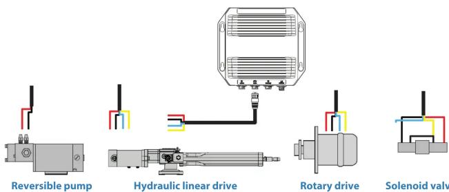
Drive (Max 8A/12A Continuous/Peak)

Socket

Key Function Color
| 1 Clutch GND/Solenoid Common | Yellow |
| 2 Clutch | Blue |
| 3 Motor_A | Red |
| 4 Motor_B | Black |
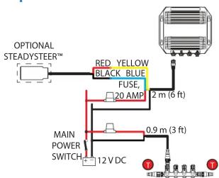
Power

Socket

Plug
Option 1

Key Function Color
| 1 - 0V DC Black | ||
| 2 + | 12 / 24V DC Red | |
| 3 | AUTO/ STBY button or SteadySteerTM(@optional) | Yellow |
| 4 B | ||
Option 2
Feedback

Socket

Plug
Key Function Color
| 1 + 5V DC Red | |
| 2 Signal | Yellow |
| 3 - 0V DC | Black |

→ Note: Navico NMEA 2000® Rudder feedback units should be connected directly to the NMEA 2000 backbone.
Marque : SIMRAD
Modèle : NAC-2
Catégorie : Électronique marine