BC3021H - Coupe-herbe Maruyama - Notice d'utilisation et mode d'emploi gratuit
Retrouvez gratuitement la notice de l'appareil BC3021H Maruyama au format PDF.


| Type de produit | Coupe-herbe (débroussailleuse) |
| Marque | Maruyama |
| Modèle | BC3021H |
| Moteur | Thermique 2 temps |
| Cylindrée | 30,1 cm³ |
| Puissance | Environ 1,5 kW |
| Carburant | Mélange essence/huile 50:1 |
| Capacité du réservoir | Environ 0,7 L |
| Poids | Environ 6,5 kg |
| Largeur de coupe | Environ 42 cm |
| Type de lame | Lame 3 dents ou tête fil nylon compatible |
| Système anti-vibration | Oui |
| Allumage | Électronique |
| Vitesse de rotation | Environ 8000 tr/min |
| Niveau sonore | Environ 95 dB(A) |
| Fonctions principales | Coupe d'herbes hautes, broussailles, ronces |
| Entretien courant | Nettoyage filtre à air, bougie, affûtage lame |
| Sécurité | Protection anti-chocs, arrêt d'urgence, harnais |
| Pièces détachées | Bougie, filtre à air, lame, tête de coupe |
| Réparabilité | Moteur accessible, pièces disponibles |
| Garantie | 2 ans pièces et main-d'œuvre |
FOIRE AUX QUESTIONS - BC3021H Maruyama
Questions des utilisateurs sur BC3021H Maruyama
0 question sur cet appareil. Repondez a celles que vous connaissez ou posez la votre.
Poser une nouvelle question sur cet appareil
Téléchargez la notice de votre Coupe-herbe au format PDF gratuitement ! Retrouvez votre notice BC3021H - Maruyama et reprennez votre appareil électronique en main. Sur cette page sont publiés tous les documents nécessaires à l'utilisation de votre appareil BC3021H de la marque Maruyama.
MODE D'EMPLOI BC3021H Maruyama
MARUYAMA
OWNER'S OPERATOR'S MANUAL
Manual del Propietario u Operador
BRUSH CUTTER CORTADORA
BC3021H
BC4320H, BC4320H-RS
BC5020H, BC5020H-RS
BCF4320H, BCF4320H-RS
BCF5020H, BCF5020H-RS

natural_image
Line drawing of a mechanical device with articulated arm and head assembly (no text or symbols)The POWER in Outdoor Power
Completely read and understand this manual before using this product. Lea y entienda este manual a fondo, antes de usar este producto
MARUYAMA
SAFETY INSTRUCTIONS
-
Read and understand this instruction Manual before using the brushcutter. Be thoroughly familiar with the proper use of the brushcutter.
-
Never allow children to operate the brushcutter. it is not a toy. Never allow adults to operate the unit without first reading the Instruction Manual.
-
Become familiar with the controls and know how to stop the engine quickly.
-
ALWAYS WEAR SAFETY GLASSES or other suitable eye protection, and hearing protection.
-
Keep the area of operation clear of all persons, particularly small children and pets.
-
Never operate a brushcutter when you are fatigued.
-
Never operate without proper guards or other protective safety devices in place.
-
Dress properly; do not wear loose clothing or jewelry. They can be caught in moving parts. Always wear substantial footwear, long pants and long sleeved shirt.
-
Gasoline is highly flammable; handle it carefully. Fill the fuel tank with the correct mixture of gasoline and oil before trying to start the engine.
-
Use an approved fuel container to store the gasoline/oil mixture.
-
Do not fill the tank when the engine is hot or running.
-
Do not smoke while handling gasoline.
-
Fill the fuel tank outdoors and up to about 10mm from the top of the tank, not the top of the filler neck.
-
Wipe any spilled gasoline before starting the engine.
-
Always be sure of your footing; keep a firm hold of the handles with both hands, and walk, never run.
-
Use the right tool for the job. Do not use the brushcutter for any job that is not recommended by the manufacturer.
-
Keep all fasteners tight to be sure the brushcutter is in safe working condition. Follow the maintenance instructions provided on page US-6 of this manual.
-
Do not put hands or feet near or under the rotating parts.
-
Keep clear at all times.
-
If the brushcutter should start to vibrate abnormally, stop the engine and check immediately for the cause. Vibration is generally a warning of trouble.
-
Do not trim too close to the ground in order to avoid hitting small stones or other debris. Avoid using the brush-cutter near rocks, gravel, stones and similar matter.
-
Use the brushcutter only in daylight or good artificial light.
-
Shut off the engine and be certain the cutting blade has completely stopped rotating before inverting the machine.
SAFETY INSTRUCTIONS
| MODEL | BC3021H | BC4320H | BC4320H-RS | BC5020H | BC5020H-RS | BCF4320H | BCF4320H-RS | BCF5020H | BCF5020H-RS |
| Dry Weight (kg) | 6.0 | 8.1 | 8.2 | 8.1 | 8.2 | 8.4 | 8.5 | 8.4 | 8.5 |
| Handle Configuration | Horn Handle | ||||||||
| Engine Displacement (cc) | 30.1 | 41.5 | 41.5 | 49.9 | 49.9 | 41.5 | 41.5 | 49.9 | 49.9 |
| Fuel Tank Capacityr (l) | 0.6 | 1.0 | |||||||
| Carburetor | Diaphragm Type | ||||||||
| Ignition | Solid State System | ||||||||
| Spark Plug | NGK BPM8Y Set Gap 0,6 - 0,7 mm | ||||||||
| Fuel Mixture | Use Only Non - Leaded Regular Gasoline.2 - Cycle Oil Mix 25:1 Ratio Must Be Approved For Air - Cooled Engines. | ||||||||
Product Description
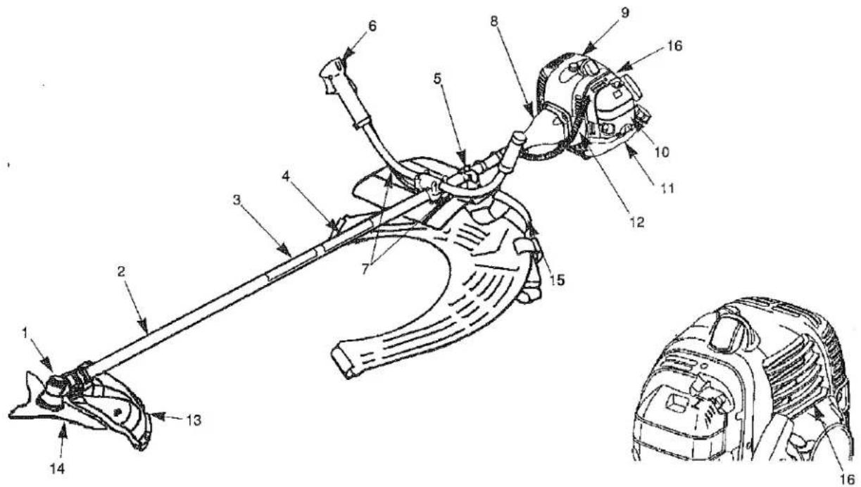
- Gearcase
- Shaft Assembly
- Model Name
- Safety Decal
- Attachment Ring for Shoulder Harness
- Throttle Trigger and Stop Switch
- Handlebar
-
Clutch Drum Housing
-
Engine
- Air Filter
- Fuel Tank
- Throttle Cable and Stop Switch Wires
- Debris Shield
- Cutting Blade
- Shoulder Harness
- Serial Number (on rear of engine)
ASSEMBLY INSTRUCTIONS
ENGINE AND DRIVESHAFT ASSEMBLY
Attach the clutch drum housing to the engine using the four screws.
HORN HANDLES
- Loosen the four screws on the top of the clamp bracket.
- Insert the left and right horn handles into the clamp bracket.
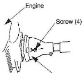
Clutch Drum Housing

Clamp Bracket
CONNECTING THROTTLE CABLE AND STOP SWITCH WIRES
- Insert the throttle cable through the carburetor bracket, then screw a cable adjuster sleeve into the carburetor bracket fully.
- Position the slotted fitting on the carburetor so the recessed hole for the lug is away from the cable adjuster sleeve.
- Rotate teh carburetor throttle cam and slip the throttle cable through the slot in the slotted fitting, making sure the cable lug drops into the recessed hole.
- Operate the throttle trigger a few times to make sure that it works correctly.
- Adjust the cable adjuster sleeve so the stop on the carburetor throttle cam just contacts the throttle stop and the cable position keep 1-2mm play between cable lug and slotted fittings when the throttle trigger is fully depressed.
- When the throttle cable is adjusted correctly, tighten the lock-nut.
- Plug the stop switch wires into the matching connectors from the engine. Note that wire polarity is not important.
[Except a BC3021H]
- Lap and fix the stop switch wires and connectors with clamp.
[BCF4320H, BCF4320H-RS, BCF5020H, BCF5020H-RS]
Clamp the throttle cable assembly with two bands as shown.
[BC4320H, BC4320H-RS, BC5020H, BC5020H-RS]
Clamp the throttle cable assembly as shown.

1-2mm Play

![Clamp [Except a BC3021H]](/content/2026/06/1383619/images/869bc1c90c396cbc090e17e46056736f3fb657d9cfa27ac1a87d52249cc39d51.jpg)
![Throttle Cable Assembly Band (2) [BCF4320H, BCF4320H-RS, BCF5020H, BCF5020H-RS]](/content/2026/06/1383619/images/4d591281de73fa2e38e516c7612ae0582069c66759eb59892fb167d19cffb34d.jpg)
![[BC4320H, BC4320H-RS, BC5020H, BC5020H-RS]](/content/2026/06/1383619/images/375c5475f4e3270ae757d0823ef443d520fa0e50ea5ffa786d8807bdd8780c58.jpg)
[BCF4320H, BCF4320H-RS, BCF5020H, BCF5020H-RS]
Caution! : This swivel stopper is exclusively for fixing the handle in transport.
Do not engage the swivel stopper while operating the brushcutter.
In transport:
Loosen the wing nut, place the stopper on A position of the bracket. Tighten the wing nut, confirm the handle is fixed by the swivel stopper.
In operation: Before start operation of the brushcutter, disengage the swivel stopper. Loosen the wing nut, place the stopper at B position. Tighten the wing nut to fix there, confirm the handle becomes free to turn around.
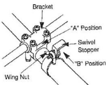
[BCF4320H, BCF4320H-RS, BCF5020H, BCF5020H-RS]
DEBRIS SHIELD
Attach the debris shield to the gearcase with the two M6 x 30 screws as shown on Fig. 1.

SHIELD EXTENSION
(Install the string cutoff blade and shield extension to the debris shield.)
- Insert the square nut into shield extension as shown on Fig. 2.

- Attach the String Cutoff Blade to shield extension using M5 x 20 Screw, locking with square nut (on Fig.2) as shown on Fig.3.
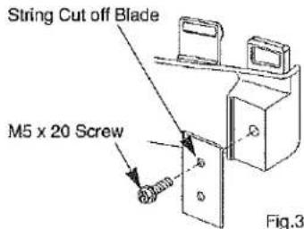
- Enter the guide in the slot of debris shield on Fig. 4. Make sure place the three hooks into the position on the shield as shown on Fig.5.

CUTTING BLADE
A variety of metal cutting blades are available to satisfy different cutting conditions. It is especially important to use only the correct blade(s) approved for each model brushcutter. Also, it is especially important to install the blade for LEFT-HAND rotation (as viewed from the operator's position), and to correctly position all blade holding parts (see sketch).
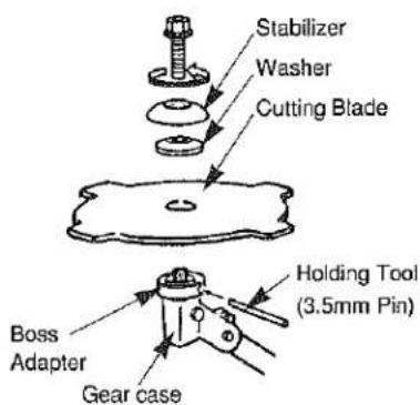
BEFORE OPERATION
FUEL : MIXING GASOLINE AND OIL
The two cycle engines used in the brushcutter requires a mixture of GASOLINE and OIL for lubrication of bearings and other moving parts. The proper fuel mixture ratio is 25:1, which is 40cc of oil mixed with one liter of gasoline.
NOTE: Gasoline and oil must be premixed in a clean gasoline container. Never mix gasoline and oil indoors or in the burushcutter fuel tank. Always use fresh gasoline.
WARNING !! - NEVER USE GASOHOL OR ALCOHOL BLENDED FUELS IN MARUYAMA ENGINES.
Before filling the brushcutter fuel tank, clean around the fuel tank cap so dirt and debris does not enter the fuel tank. Always shake the fuel container before filling the fuel tank. Remove the fuel cap, then fill the fuel tank to within about 10mm from the top of the tank. Avoid filling the fuel tank filler neck. Install the cap securely onto the fuel tank.
OPERATING INSTRUCTIONS Starting and Stopping
COLD STARTING PROCEDURE
The carburetor on this engine is equipped with a fuel primer and a choke system. To start a "cold" engine properly, perform the following procedure:
- Pump the primer bulb until fuel can be seen flowing through the fuel return line to the fuel tank. (Flowing fuel should be almost clear, not foamy or full of bubbles.)
- Turn the choke lever to the Close position.
- With the stop switch "ON", and the throttle trigger positioned at Fast-idle position, pull the starter grip.
After the engine is started, turn the choke lever to the Open position. Then squeeze and release the throttle trigger to allow it to return to the idle position.
If the engine stops running before you turn the choke lever to the open position:
Go ahead and open the choke, pull the starter grip with the throttle trigger positioned at Fast-idle position.
![Choke Lever Primer Bulb Fuel Return Line [BC3021H] Starter Grip](/content/2026/06/1383619/images/6088f6ca64b55132593e4bfd335834bd810ce7dbdf335b37c5d583c705487ad0.jpg)
![Primer Bulb Fuel Return Line Starter Grip Choke Lever [Except a BC3021H]](/content/2026/06/1383619/images/2ab7bcef0db2deb615e8133176ea8d2a8a932c8004aea8d06d6ee11696dc4bb7.jpg)
HOT RESTART
To start the engine that is already warmed up (hot restart), or if the ambient temperature exceeds 68^(20^) :
- Pump the primer bulb until fuel can be seen flowing through the fuel return line to the fuel tank. (Flowing fuel should be almost clear, not foamy or full of bubbles.)
- Turn the choke lever to the open position, and set the stop switch to the "ON" position.
- Leave the throttle trigger in the idle position and pull the starter grip. If the engine fails to start after you follow the above procedures, contact an authorized MARUYAMA dealer.
TO STOP THE ENGINE:
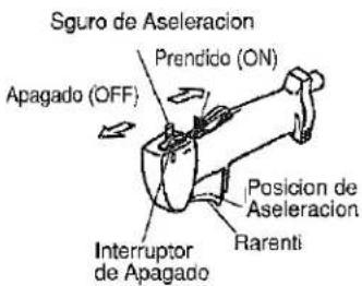
- Release the throttle trigger.
- Slide the stop switch to "STOP" position.

CARBURETOR ADJUSTMENT
The carburetor has been carefully adjusted at the factory and should not require any further adjustment. Only the idling speed can be adjusted by turning the idle speed adjustment screw (see sketch). The correct speed for model BC3021H is 2700 - 3300 RPM, and for others are 2400 - 2800 RPM (or just below the clutch engagement speed). Turning the adjustment screw clockwise will increase the idle speed.
If further adjustment is necessary, please contact a local authorized MARUYAMA dealer.
Idle Speed Adjustment Screw

natural_image
Technical line drawing of a vehicle engine compartment showing engine, valve, and housing components (no text or labels)[BC3021H]
[Except a BC3021H]
OPERATING THE BRUSHCUTTER
MARUYAMA brushcutters are designed and tested to cut nearly all grasses, thick weeds and brush. As you continue to use the equipment, many tasks will become easier.
CAUTION-Adjust the blade guard to a position that does not make contact with the blade or trimming line, and shields the operator from thrown debris.
CAUTION-Read the SAFETY INSTRUCTIONS concerning the proper use of the brushcutter on page(1).
CAUTION-Observe all warnings that appear on the brushcutter.
CAUTION-Use only the correct blade approved for the task and the machine.
CAUTION-Always use the Shoulder Hanging Strap when operating a brushcutter with a metal blade. The brushcutter must be positioned to the right side of the operator when used with a metal blade.
CAUTION-Always make certain the blade is installed to rotate in the proper direction and that all holding and fastening parts are correctly secured.
CAUTION-Remove the holding tool (É"3.5mm pin) before operating the equipment!
CAUTION-Do not continue to use a blade that is dull, damaged, or that vibrates during use. Whenever a cutting blade becomes clogged with debris, immediately stop the machine and clean the blade.
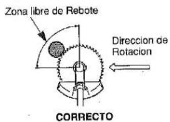
CAUTION-When cutting heavy blush or small trees, use the proper method to avoid dangerous "KICK-BACK" (see sketch).


REGULAR MAINTENANCE
AIR FILTER
The air filter should be cleaned each time the brushcutter is used. (Or more often with extreme conditions.) Remove the filter cover and take out the element. Wash the element in kerosene or warm detergent, then squeeze it dry. Apply oil (#30 wt.) to foam, removing all excess oil. Assemble and reinstall the element and filter cover.
![Filter Cover Knob Filter Screen Foam Element [BC3021H]](/content/2026/06/1383619/images/305b0511561d285129836e5dd164480138cfa5057c91d576b08f0d05c071515b.jpg)
![Filter Cover Knob Foam Element [Except a BC3021H]](/content/2026/06/1383619/images/68cc3e3ff095532208e965b4804c35f1792b1a71d34155b84105ab287a122c2f.jpg)
SPARK PLUG
The spark plug should be removed from the engine and checked after each 25 hours of operation. The tips can be cleaned with a stiff brush. Adjust the gap to 0,6-0,7mm (see sketch). Replace the spark plug if it is oil_fouled or damaged, the average spark plug life is approximately 100 hours.
CAUTION-Do not over_tighten the spark plug. The correct torque is 10.7-16.6N·m(100-160 kgf·cm)
COOLING FINS CLEANING
- Loosen the knob (and screw: BC3021H) and lift off the cylinder cover.
- Clean all dirt and debris from the cooling fins and from around the cylinder base.
- Reinstall the cylinder cover.
FUEL FILTER
The fuel filter is attached to the end of the fuel pick_up hose inside the fuel tank. After each 25 hours of use, it should be checked for dirt or damage, and replaced if necessary. Using a wire hook, gently pull the fuel filter out through the fuel filler opening. Grasp the fuel hose next to the fuel filter fitting and remove the filter, but do not release the hose. While still holding on to fuel hose, attach the new fuel filter. Drop the new fuel filter back into the fuel tank. Make sure that the fuel filter is not stuck in a corner of the tank, and that the fuel hose is not doubled over (kinked) before refueling.
LUBRICATION : GEARCASE
The gearcase should be checked for lubrication after each 30 hours of use. Remove the cutting attachment and the boss adapter. Clean any dirt and debris from the area between the boss adapter and the gearcase. Remove the grease plug from the side of the gearcase. While rotating the attaching shaft, Inject lithium base bearing lube (P/N 211337) through the plug hole until the gearcase is full. Reinstall the boss adapter and grease plug.
![Tips 0.6-0.7mm Filter Cover Cylinder Cover Screw Knob Cooling Fins [CBC3021H] Cylinder Cover Knob Cooling Fins [Except a BC3021H]](/content/2026/06/1383619/images/904f15096f0b9ddc5e6f7e53e36788743c4f8b4e6f4bc67ac1b47392e60ac4fc.jpg)


GENERAL CLEANING AND TIGHTENING
The MARUYAMA brushcutter will provide maximum performance for many, many hours if it is maintained properly. Good maintenance includes regular checking of all fasteners for correct tightness, and cleaning the entire machine.
STORAGE
For long term storage of the Brushcutter, perform all regular maintenance procedures and needed repairs. Empty the fuel tank. Start the engine and allow it to run until it stops. Pull the starter cord a few times to remove any excess fuel from the engine. Remove the spark plug and insert a small amount of oil. Pull the starter cord once and bring the piston to a position closest to the spark plug hole. Reinstall the spark plug. Store the brushcutter in a dry place away from excessive heat, sparks or open flame.

MARUYAMA
INSTRUCCIONES DE SEGURIDAD
- Lea y entienda este Manual de Instrucciones antes de usar este producto. Familiarícese a fondo con el uso adecuado de este equipo.
- Nunca permita que los niños operen la Cortadora de Maleza. Este no es un juguete. Nunca permita que adultos operen la unidad sin antes haber leído el Manual de Instrucciones.
- Familiarícese con los controles de la máquina y aprenda la forma de interrumpir su operación rápidamente.
- SIEMPRE USE GAFAS DE SEGURIDAD o cualquier otra protección apropiada para los ojos y emplee también protección apropiada para los oídos.
- No permita el acceso de gente o animales al área de trabajo, especialmente de niños o mascotas.
- Nunca opere la cortadora de maleza cuando se sienta cansado o fatigado.
- Nunca opere la máquina sin sus debidos resguardos o elementos de protección o seguridad correctamente instalados.
- Vista en forma apropiada para el trabajo, sin ropa o adornos sueltos. Estos pueden enredarse en los elementos móviles de la máquina. Siempre use calzado fuerte, pantalones largos y camisas de manga larga.
- La gasolina es altamente inflamable, y por lo tanto manéjela con cuidado. Llene el tanque de combustible con la mezcla indicada de gasolina y aceite antes de tratar de encender el motor.
- Use un recipiente apropiado para gasolina para guardar la mezcla de gasolina y aceite.
- No llene el tanque cuando el motor esté operando o esté caliente.
- No fume cuando esté manejando gasolina.
- Llene el tanque de combustible al aire libre y hasta un nivel de unos 10 mm. del borde del tanque, no del borde del cuello de llenado
- Limpie cualquier cantidad de gasolina que se haya derramado, antes de encender el motor.
- Párese siempre en forma estable y segura, agarre firmemente, con ambas manos los manubrios y camine, nunca corra.
- Use siempre la herramienta apropiada para el trabajo que va a realizar. No use la cortadora de maleza para trabajos que el fabricante no recomienda.
- Asegúrese de que todos los elementos de sujeción estén en su lugar y bien ajustados. Siga las instrucciones de mantenimiento, empezando en la página ES-6 de este Manual
- No acerque las manos o los pies a las piezas móviles.
- Manténgase fuera del alcance de estas piezas en todo momento.
- Si se presentan problemas de marcha o de excesiva vibración, detenga el motor inmediatamente e inspeccione la unidad para localizar la causa. La vibración generalmente indica que hay problemas mecánicos.
- No corte demasiado cerca de la superficie del suelo para evitar que la cuchilla golpee guijarros u otros des- perdicios. Evite usar la cortadora de maleza en zonas de roca, gravilla, piedra y materiales similares.
- Use la cortadora de maleza únicamente de día o con buena luz artificial.
- Apague el motor y cerclórese que la cuchilla ha dejado de girar completamente antes de invertir la máquina.
ESPECIFICACIONES
| MODEL | BC3021H | BC4320H | BC4320H-RS | BC5020H | BC5020H-RS | BCF4320H | BCF4320H-RS | BCF5020H | BCF5020H-RS |
| PESO SECO (kg) | 6.0 | 8.1 | 8.2 | 8.1 | 8.2 | 8.4 | 8.5 | 8.4 | 8.5 |
| CONFRIGURACION DEL MANUBRIO | Horn Handle | ||||||||
| DESPLAZAMIENTO DEL MOTOR (cc) | 30.1 | 41.5 | 41.5 | 49.9 | 49.9 | 41.5 | 41.5 | 49.9 | 49.9 |
| CAPACIDAD DEL TANQUE DE COMBUSTIBLE( ) | 0.6 | 1.0 | |||||||
| CARBURADOR DE TIPO DIAFRAGMA | DIAPHRAGM TYPE | ||||||||
| ENCENDIDO | SISTEMA DE ESTADO SOLIDO | ||||||||
| BUJIA | NGK BPM8Y LUZ ENTRE ELECTRODOS 0.6 a 0.7 mm | ||||||||
| MEZCLA DE COMBUSTIBLE | USE UNICAMENTE GASOLINA REGULAR SIN PLOMO. MEZCLA 25:1 DE ACEITE PARA MOTOR DE 2 CICLOS. DEBE SER APROBADO PARA MOTOR ENFRIADO POR AIRE. | ||||||||
DESCRIPCION DEL PRODUCTO

- Caja de Engranajes
- Montaje del eje
- Modelo
- Símbolos para la Seguridad
- Anillo de Montaje de la Arnés para el Hombro
- Disparador del Acelerador e Interruptor de Parada
- Manijas de cuerno
-
Carcasa del Embrague
-
Motor
- Filtro del Aire
- Depósito de Combustible
- Cables del Acelerador e Interruptor de Parada
- Protector del Accesorio de Corte
- Cuchilla de Corte
- Arnés para el Hombro
- Número de Serie
INSTRUCCIONES PARA EL ARMADO
ARMADO DEL EJE DE IMPULSION Y EL MOTOR
Fije al motor la carcaza del tambor del embrague usando los cuatro tornillos.
MANIJAS DE CUERNO
- Afloje los cuatro tornillos que encuentra sobre el soporte de abrazadera.
- Inserte en el soporte de abrazadera las manijas de cuerno, izquierda y derecha.


CONEXIÓN DEL CABLE DEL ACELERADOR Y DE LOS CABLES DEL INTERRUPTOR DE PARADA
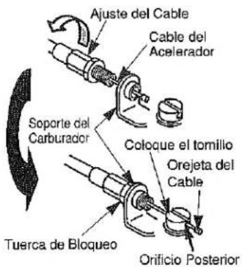
- Inserte el cable del acelerador por el soporte del carburador, después atornille con cuidado el manguito de ajuste del cable en el soporte del carburador.
- Coloque el tornillo en el carburador de modo que el orificio posterior para la orejeta del cable quede siempre alejado del manguito de ajuste del cable.
- 'Gire la leva del acelerador del carburador y deslice el cable del acelerador por la ranura del tornillo, asegurándose de que la leva del cable sobresale por el orificio posterior.
- Presione el acelerador unas cuantas veces para asegurarse de que funciona correctamente.
- Ajuste el manguito de ajuste del cable de modo que la leva del acelerador del carburador contacte exactamente con la parada del acelerador y la posición del cable mantenga una holgura de 1-2 mm entre le orejeta del cable y el tornillo al apretar el acelerador hasta el fondo.
- Cuando el cable del acelerador esté ajustado correctamente, apriete la tuerca de bloqueo.
- Conecte los cables del interruptor de parada en los conectores correspondientes del motor. Recuerde que la polaridad de los cables no es importante.
[EXCEPCIÓN DE BC3021H]
- Gire y fije los cables del interruptor de parada y los conectores con la abrazadera.
[BCF4320H, BCF4320H-RS, BCF5020H, BCF5020H-RS]
Asegure el conjunto del cable con las dos bandas como se ilustra en la figura.
[BC4320H, BC4320H-RS, BC5020H, BC5020H-RS]
Asegure el conjunto del cable como se ilustra en la figura.
BCF4320H, BCF4320H-RS, BCF5020H, BCF5020H-RS
¡Precaución! : El elemento que inmoviliza la acción giratoria debe usarse exclusivamente para fijar el manubrio durante el transporte de la máquina. No enganche este mecanismo cuando la máquina está operando.
En transporte:
Afloje la tuerca de mariposa y coloque el fiador de eje en la posición "A" del soporte. Apriete, la tuerca de mariposa y verifique que el manubrio ha quedado inmovilizado por el elemento.
Cuando vaya a operar la máquina:
Antes de comenzar la operación de la cortadora de maleza, desenganche el elemento inmovilizador. Afloje la tuerca de mariposa, coloque el elemento inmovilizador en la posición B y apriete la tuerca de mariposa para fijarlo en tal lugar. Confirme que el manubrio queda libre de girar en redondo.

![Abrazadera [Excepción de BC3021H]](/content/2026/06/1383619/images/8d54b3d124be059baa2a077832765f0f0f0ba44101b1b692fce9fb9b7c0b6209.jpg)
![Cable de Acelerador Completo Bandas (2) [BCF4320H, BCF4320H-RS, BCF5020H, BCF5020H-RS]](/content/2026/06/1383619/images/9de88f1072fbd23b460ff160023a94d203e30e14380f05973737c9b04ac534a5.jpg)
![[BC4320H, BC4320H-RS, BC5020H, BC5020H-RS]](/content/2026/06/1383619/images/f52c4aa6d22487ab7d25a3ae1c49fc5fa000c578554243aae13cb85dee53bbe9.jpg)

[BCF4320H, BCF4320H-RS, BCF5020H, BCF5020H-RS]
PROTECTOR DE LA CUCHILLA
Fije el protector de la cuchilla a la caja del equipo rotor con dos tornillos M6 x 30 como se indica en la ilustración Fig 1.

PROTECTOR CABEZAL DE NYLON
(Instale la cuchilla que limita la longitud del hilo sobre la extensión del protector.) 1. Coloque la tuerca cuadrada en la extensión del protector. Ver Fig.2
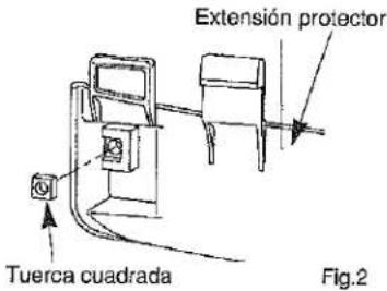
- Coloque la cuchilla que limita la longitud del nylon utilizando el tornillo de M5x20 bloqueado con la tuerca cuadrada. Ver Fig. 2 y Fig. 3.

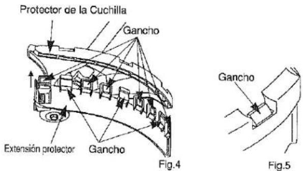
- Coloque la extensión del protector en los agujeros como se muestra en la fig 4. Asegurándose que las pestañas Fig. 5 entran en la posición correcta.
CUCHILLA DE CORTE
Existe una variedad de cuchillas para satisfacer diferentes condiciones de corte. Es particularmente importante usar la cuchilla o cuchillas apropiadas para el trabajo y aprobadas para ser instaladas en los modelos específicos de las cortadoras de maleza. También es especialmente importante asegurarse de que la cuchilla sea de rotación hacia la izquierda - LEFT - HAND (dirección contraria a las manecillas del reloj), vista desde la posición del operador, y colocar correctamente todos los elementos que fijan la cuchilla.

ANTES DE OPERAR LA MAQUINA
COMBUSTIBLE: LA MEZCLA DE GASOLINA Y ACEITE
Los motores de dos ciclos que se usan en la cortadora de maleza requieren como combustible una mezcla de GASOLINA y ACEITE para la lubricación de cojinetes y otros elementos móviles. Las proporciones correctas de esta mezcla son 25:1 que corresponden a 40 cc. de aceite en un litro de gasolina.
NOTA : Siempre mezcle por anticipado la gasolina y el aceite en un recipiente limpio, aprobado para gasolina. Nunca mezcle la gasolina y el aceite en un recinto interior o utilizando, para hacer la mezcla, el tanque de la máquina. Use siempre gasolina fresca.
¡ADVERTENCIA!! NUNCA USE EN MOTORES MARUYAMA GASOHOL O COMBUSTIBLES MEZCLADOS CON ALCOHOL.
Antes de llenar el tanque de combustible, limpie alrededor de la tapa del tanque para evitar que mugre o desechos entren al tanque cuando se encuentra destapado. Cierre el recipiente y agítelo por un momento para mezclar bien el aceite y la gasolina antes de llenar el tanque de la Cortadora de Maleza. Remueva la tapa y luego llene el tanque hasta unos 10 mm. del borde. Evite llenar el cuello de la boca del tanque y vuelva a colocar la tapa en forma segura.
INSTRUCCIONES DE OPERACION ARRANQUE Y PARADA
PROCEDIMIENTO PARA EL ARRANQUE EN FRIO
El carburador de este motor cuenta con un sistema cebador. Para arrancar un motor "en fric" de manera adecuada, siga el siguiente procedimiento:
- Bombeé el cebador hasta que el combustible pueda verse a través del tubo de combustible y que este se dirije al tanque de combustible. La corriente de combustible deberá verse casi claramente, que no esté lleno de burbujas de aire.
- Cierre la palanca del ahogador llevándola a la posición de cerrada.
- Con el dispositivo de encendido en "ON" encendido, y el gatillo del acelerador en la posición de ralentí rápido, tire del cordel de arranque. Tire de la cuerda de arranque de retroceso hasta que se pueda ver la marca verde en la cuerda. El motor rotará por la fuerza del principal resorte incorporado. No tire de la cuerda de arranque de retroceso rápidamente. Tire de la cuerda suavemente justo hasta que pueda ver la marca verde en la cuerda, y luego retórnela suavemente. Después que el motor haya arrancado, lleve la palanca del ahogador a la posición de "Open" abierta. Entonces accione y afloje el gatillo del acelerador para dejar que vuelva a la posición de ralentí. Si el motor se para, pon usted el acelerador en la posición de abierto "Open": Siga y abrá el ahogador, tire del la palanca de arranque con el gatillo del acelerador puesto en posicion en ralentí rápido "Fast Idle".
ARRANQUE EN CALIENTE
Para volvera arrancar el motor una vez de que éste caliente (arranque en caliente).
- Ponga la palanca del ahogador en la posición de abierta "Open", y ponga el dispositivo de arranque en la posición de arranque "ON".
- Deje el gatillo del acelerador en la posición de ralentí y tire de la empuñadura de arranque.
- Si el motor no arranca después de tres o cuatro intentos, siga las instrucciones del procedimiento de arranque en Frio en la sección de arriba. Si el motor tampoco arrancase siguiendo el procedimiento arriba descrito, póngase en contacto con el concesionario de Maruyama.
PARA PARAR EL MOTOR
- Suelte el gatillo del acelerador
- Ponga el dispositivo de parada en la posición "STOP" (parada).
![Palanca de Ahogador Vulva de Arranque Tubo de Retorno Agarrdera de Arranque [BC3021H] Vulva de Arranque Tubo de Retorno Agarrdera de Arranque Palanca de Ahogador [Excepción de BC3021H]](/content/2026/06/1383619/images/fe7df2e38df863c2b9e217c65a29e0de814282422d07b0b3d625e0531471ef50.jpg)
AJUSTE DEL CARBURADOR
El carburador ha sido cuidadosamente calibrado en fábrica y no debe requerir posteriores ajustes. Unicamente la velocidad de marcha en vacío puede ajustarse girando el tornillo de ajuste de velocidad de marcha en vacío (véase la Figura). La velocidad correcta para el Model BC3021H es de 2700a 3300 R.P.M y de 2400 a 2800 R.P.M para los demás modelos (que es justo bajo la velocidad de engranaje del embrague) Al girar el tornillo de ajuste en la dirección de las manecillas del reloj se aumenta la velocidad de marcha en vacío. Si se necesitan mayores ajustes, por favor póngase en contacto con un distribuidor local autorizado por MARUYAMA.
![Perno de Ajuste de Ralenti [BC3021H] [Excepción de BC3021H]](/content/2026/06/1383619/images/bc512e1f19bcadddfa174604f7ba907050c88b8a2b16f1b6c631625fea30b65f.jpg)
OPERACION DE LA CORTADORA DE MALEZA
Las cortadoras de maleza de MARUYAMA han sido diseñadas y probadas en el corte de casi cualquier tipo de pasto, maleza gruesa y vegetación tupida. A medida que usted continúa usando el equipo muchas de las tareas se le harán más fáciles.
PRECAUCION - Ajuste el reguardo o protección de la cuchilla a una posición que no haga contacto con la cuchilla o la línea cortadora y en la que proteja al operador de desperdicios que pueda lanzar la máquina.
PRECAUCION - Lea las INSTRUCCIONES DE SEGURIDAD en cuanto al uso apropiado de la cortadora de maleza que se encuentran en la página (8).
PRECAUCION - Observe todas la precauciones que aparecen en la cortadora de maleza.
PRECAUCION - Use el tipo el tipo de cuchilla apropiada para la máquina y aprobado para realizar la tarea a realizar.
PRECAUCION - Siempre use la Correa de Colgar al Hombro cuando opere la cortadora de maleza con una cuchilla metálica. La cortadora de maleza debe ponerse en el lado derecho del operador cuando se usa una cuchilla metálica.
PRECAUCION - Siempre verifique que la cuchilla se ha instalado para girar en la dirección apropiada y que todos los elementos de fijación e instalación están correctamente colocados y asegurados.
:PRECAUCION - Quite el elemento de inmovilización (perno de 3.5 mm) antes de operar el equipo!
PRECAUCION - No use una cuchilla sin filo, averiada o que produce vibración al usarse. Cuando la cuchilla se atasca con desperdicios apague el motor inmediatamente y limpie la cuchilla.
PRECAUCION - Cuando corte vegetación tupida o arbustos pequeños use el método apropiado para evitar el peligroso "KICK BACK" (que se ilustra en la figura).

MANTENIMIENTO REGULAR
FILTRO DE AIRE
El filtro de aire debe limpiarse cada vez que se ha usado la cortadora de maleza (o aún con más frecuencia en condiciones extremas). Remueva la cubierta del filtro y saque el elemento. Lave el elemento en kerosén o con un detergente en agua tibia. Y luego, séquelo, exprimiéndolo. Aplique aceite (#30 wt.) al elemento de espuma y remueva el exceso de aceite. Arme y vuelva a instalar el filtro de aire y la cubierta del element.
![Covertura de Filtro Filtro pantalla Tornillo Element Espumoso [BC3021H]](/content/2026/06/1383619/images/5786be977e52e2127e6fd245480dc884af537cd6a70a8090e3ac050314f3add9.jpg)
![Covertura de Filtro Tornillo Element Espumoso [Excepción de BC3021H]](/content/2026/06/1383619/images/01b79b153f2c0e05f29af48154bb327ce123a70f45b05eb157041f8e2257b89f.jpg)
BUJIA
La bujía debe removerse del motor después de 25 horas de operación. Limpie los electrodos con un cepillo fuerte. Ajuste la distancia o luz entre electrodos a unos 0.6 - 0.7 mm. (vea la figura). Reemplace la bujía si está averiada o dañada por el aceite. La vida útil de una bujía es de aproximadamente 100 horas.
PRECAUCION - No apriete demasiado la bujía. El estuerzo de torsión correcto es de 10.7-16.6N·m(100-160 kgf·cm)
LIMPIEZA DE LAS ALETAS DEL CILINDRO
- Quite el pomo y la tapa del cilindro.
- Limpie las aletas de refrigeración del cilindro y su entorno.
- Vuelva a colocar la tapa.
FILTRO DE COMBUSTIBLE
El filtro de combustible se encuentra dentro del tanque de combustible, en el extremo de la manguera que lleva el combustible al cilindro. Después de cada 25 horas de operación, el filtro debe ser revisado para detectar acumulaciones de residuos o daños y ser reemplazado si es necesario. Use un gancho de alambre y suavemente saque el filtro de combustible a través de la abertura del filtro. Tome la manguera de combustible y remueva el accesorio del filtro de combustible, remueva el filtro pero no suelte la manguera. Manteniendo aún la manguera en la mano, fije el nuevo filtro de combustible y devuelva al tanque el conjunto del filtro. Verifique que el filtro de combustible no quede metido en una esquina del tanque y que la manguera de combustible no queda doblada o estrangulada, antes de proceder a llenar el tanque de combustible.
LUBRICACION DE LA CAJA DE ENGRANAJES
La caja de engranajes deberá lubricarse después de cada período de 30 horas de uso. Retire el aditamento de corte y el adaptador de copa. Limpie la mugre y desechos del área entre el adaptador de copa y la caja de engranajes. Retire el tapón de engrase del lado de la caja de engranajes. Gire el eje, a la vez que inyecta un lubricante para rodamientos a base de litio (P/N 211337) a través del hueco de engrase, hasta que liene la caja de engranajes. Reinstale el adaptador de copa y el tapón de engrase.

![Covertura de Filtro Tapa del cilindro Pomo Tornillo [BC3021H]](/content/2026/06/1383619/images/91554d76e72ef8550207e37084cfa211aac13a9eb6f8441c0ca7c7c674b2ee46.jpg)
![Tapa del cilindro Pomo Aletas del cilindro [Excepción de BC3021H]](/content/2026/06/1383619/images/6c052ba20570838aac1c7b1836819bf51578a59758dfb9251203175066f1173b.jpg)


LIMPIEZA GENERAL Y AJUSTE
La cortadora de maleza MARUYAMA proporcionará un desempeño máximo por muchas, muchas horas si se mantiene adecuadamente. El buen mantenimiento incluye la verificación regular del ajuste correcto de todos los sujetadores y la limpieza de toda la máquina.
ALMACENAMIENTO
Para almacenamiento de la cortadora de maleza por un tiempo prolongado, siga todos los procedimientos regulares de mantenimiento y haga todas las reparaciones que sean necesarias. Remueva la bujía y ponga una pequeña cantidad de aceite. Halando la cuerda de arranque mueva el pistón hasta que llegue a la posición mas cercana al agujero donde se coloca la bujía. Vuelva a instalar la bujía. Guarde la cortadora de maleza en un lugar seco, alejado de fuentes de calor, chispas o llama abierta.
- MARUYAMA
- OWNER'S OPERATOR'S MANUAL
- Manual del Propietario u Operador
- BRUSH CUTTER CORTADORA
- SAFETY INSTRUCTIONS
- Product Description
- ASSEMBLY INSTRUCTIONS
- ENGINE AND DRIVESHAFT ASSEMBLY
- HORN HANDLES
- CONNECTING THROTTLE CABLE AND STOP SWITCH WIRES
- [Except a BC3021H]
- [BCF4320H, BCF4320H-RS, BCF5020H, BCF5020H-RS]
- [BC4320H, BC4320H-RS, BC5020H, BC5020H-RS]
- DEBRIS SHIELD
- SHIELD EXTENSION
- CUTTING BLADE
- BEFORE OPERATION
- FUEL : MIXING GASOLINE AND OIL
- OPERATING INSTRUCTIONS Starting and Stopping
- COLD STARTING PROCEDURE
- HOT RESTART
- TO STOP THE ENGINE:
- CARBURETOR ADJUSTMENT
- OPERATING THE BRUSHCUTTER
- REGULAR MAINTENANCE
- AIR FILTER
- SPARK PLUG
- COOLING FINS CLEANING
- FUEL FILTER
- LUBRICATION : GEARCASE
- GENERAL CLEANING AND TIGHTENING
- STORAGE
- INSTRUCCIONES DE SEGURIDAD
- DESCRIPCION DEL PRODUCTO
- INSTRUCCIONES PARA EL ARMADO
- ARMADO DEL EJE DE IMPULSION Y EL MOTOR
- MANIJAS DE CUERNO
- CONEXIÓN DEL CABLE DEL ACELERADOR Y DE LOS CABLES DEL INTERRUPTOR DE PARADA
- [EXCEPCIÓN DE BC3021H]
- BCF4320H, BCF4320H-RS, BCF5020H, BCF5020H-RS
- PROTECTOR DE LA CUCHILLA
- PROTECTOR CABEZAL DE NYLON
- CUCHILLA DE CORTE
- ANTES DE OPERAR LA MAQUINA
- COMBUSTIBLE: LA MEZCLA DE GASOLINA Y ACEITE
- INSTRUCCIONES DE OPERACION ARRANQUE Y PARADA
- PROCEDIMIENTO PARA EL ARRANQUE EN FRIO
- ARRANQUE EN CALIENTE
- PARA PARAR EL MOTOR
- AJUSTE DEL CARBURADOR
- OPERACION DE LA CORTADORA DE MALEZA
- MANTENIMIENTO REGULAR
- FILTRO DE AIRE
- BUJIA
- LIMPIEZA DE LAS ALETAS DEL CILINDRO
- FILTRO DE COMBUSTIBLE
- LUBRICACION DE LA CAJA DE ENGRANAJES
- LIMPIEZA GENERAL Y AJUSTE
- ALMACENAMIENTO
Marque : Maruyama
Modèle : BC3021H
Catégorie : Coupe-herbe