163A - Compresseur audio DBX - Notice d'utilisation et mode d'emploi gratuit
Retrouvez gratuitement la notice de l'appareil 163A DBX au format PDF.


| Type de produit | Appareil électronique non catégorisé |
| Marque | DBX |
| Modèle | 163A |
| Dimensions (L x l x h) | 483 x 200 x 44 mm |
| Poids | 2,5 kg |
| Alimentation | Secteur 230 V AC, 50 Hz |
| Consommation | 15 W |
| Plage de température de fonctionnement | 0°C à 40°C |
| Humidité relative | 10% à 90% sans condensation |
| Entrées | 2 x XLR (symétrique) |
| Sorties | 2 x XLR (symétrique) |
| Réponse en fréquence | 20 Hz - 20 kHz |
| Rapport signal/bruit | > 100 dB |
| Distorsion | < 0,01% |
| Fonctions principales | Traitement audio, réduction de bruit, compression, gate |
| Entretien et nettoyage | Nettoyer avec un chiffon sec et doux. Ne pas utiliser de solvants. |
| Sécurité | Ne pas exposer à l'humidité ou aux chocs. Débrancher avant entretien. |
| Pièces détachées et réparabilité | Contacter le service après-vente DBX. Pas de pièces réparables par l'utilisateur. |
| Informations générales | Manuel disponible en ligne. |
FOIRE AUX QUESTIONS - 163A DBX
Questions des utilisateurs sur 163A DBX
0 question sur cet appareil. Repondez a celles que vous connaissez ou posez la votre.
Poser une nouvelle question sur cet appareil
Téléchargez la notice de votre Compresseur audio au format PDF gratuitement ! Retrouvez votre notice 163A - DBX et reprennez votre appareil électronique en main. Sur cette page sont publiés tous les documents nécessaires à l'utilisation de votre appareil 163A de la marque DBX.
MODE D'EMPLOI 163A DBX
MODEL 163A
Over Easy® COMPRESSOR/LIMITER
dbx®
OPERATION MANUAL

ATTENTION:
CAUTION
RISK OF ELECTRIC SHOCK DO NOT OPEN
RISQUE DE CHOC ELECTRIQUE - NE PAS OUVRIR

WARNING: TO REDUCE THE RISK OF FIRE OR ELECTRIC SHOCK, DO NOT EXPOSE THIS EQUIPMENT TO RAIN OR MOISTURE.
CAUTION: TO REDUCE THE RISK OF FIRE OR ELECTRICAL SHOCK, DO NOT REMOVE COVER (OR BACK). NO USER SERVICABLE PARTS INSIDE. REFER SERVICING TO QUALIFIED SERVICE PERSONNEL.

This symbol, wherever it appears, alerts you to the presence of uninsulated dangerous voltage inside the enclosure - voltage that may be sufficient to constitute a risk of shock.

This symbol, wherever it appears, alerts you to important operating and maintenance instructions in the accompanying literature. Read the manual.
All trademarks are property of their respective companies.
This manual is part number 18-1633-B © Copyright 1995 by dbx Professional Products

dbx Professional Products 8760 South Sandy Parkway Sandy, Utah 84070 Telephone (801) 568-7660 FAX (801) 568-7662
MANUAL CONTENTS
INTRODUCTION 2
INSPECTION 2
QUICK SET-UP 2
WARRANTY 3
UNDERSTANDING COMPRESSION 4
OPERATING CONTROLS 5
OPERATING NOTES 7
CONNECTING THE 163A TO YOUR SYSTEM ....9
INSTALLATION CONSIDERATIONS 10
TECHNICAL SUPPORT / FACTORY SERVICE 15
SPECIFICATIONS 16
INTRODUCTION
Congratulations on choosing the dbx Model 163A OverEasy® Compressor/Limiter. We recommend that you take a moment and read through the manual as it provides information that will assist you in using your unit to its fullest potential.
The dbx 163A provides traditional dbx sonic quality and performance for the working musician, DJ, studio operator or anyone who needs a friendly compressor/limiter/preamp. The 163A incorporates dbx OverEasy® compression with soft knee threshold, a patented dbx VCA and human-ear compatible true RMS detection. Key operating parameters are integrated and controlled by a single front panel slide control. After a simple level-set adjustment, the desired amount of compression can be rapidly and easily set or adjusted with the slider - without requiring the adjustment of separate Threshold, Ratio and Output controls as found on conventional compressors.
Front panel inputs allow quick and complete system hookup and operation that can be switched over to instrument or microphone just by "plugging in" to the front panel. This front panel Hi-Z input includes a preamp (with rear panel trim) for bass, guitar, synthesizer or other Hi-Z devices, including a Hi-Z mic (or Lo-Z mic with appropriate transformer). The standard input and output jacks on the rear panel are designed for operation at line levels from -30dBu to +10dBu.
INSPECTION
Unpack and inspect the 163A package.
Your 163A was carefully packed at the factory in a protective carton. Nonetheless, be sure to examine the unit and the carton for any signs of damage that may have occurred during shipping. If obvious physical damage is noticed, contact the carrier immediately to make a damage claim. We suggest saving the shipping carton and packing materials for safely transporting the unit in the future.
Verify that the 163A package contains the following:
○ 163A Unit
○ AC Power Cord
Operation Manual
O 163A Accessory Kit (OPTIONAL)
○ Registration Card
QUICK SETUP
To get your unit up and running as quickly as possible, do the following steps. For more detailed information, refer to the specified pages.
○ Unpack and Inspect the 163A Package. Page 2
○ Mount Unit in a Rack (OPTIONAL). Page 10
○ Connect the 163A To Your System. Page 9
○ Set Levels and Controls as Needed. Page 5
WARRANTY
This warranty is valid only for the original purchaser and only in the United States. We warrant dbx products against defects in material or workmanship for a period of two years from the date of original purchase for use, and agree to repair or, at our option, replace any defective item, except external power transformers, without charge for either parts or labor.
IMPORTANT: This warranty does not cover damage resulting from accident, misuse or abuse, lack of reasonable care, the affixing of any attachment not provided with the product, loss of parts, or connecting the product to any but the specified receptacles. This warranty is void unless service or repairs are performed by an authorized service center. No responsibility is assumed for any special, incidental or consequential damages. However, the limitation of any right or remedy shall not be effective where such is prohibited or restricted by law.
Simply take or ship your dbx product prepaid to our service department. Be sure to include your sales slip as proof of purchase date. (We will not repair transit damage under the no-charge terms of this warranty.) dbx will pay return shipping.
NOTE: No other warranty, written or oral is authorized for dbx products.
This warranty gives you specific legal rights, and you may also have other rights which vary from state to state. Some states do not allow the exclusion of limitations of incidental or consequential damages or limitations on how long an implied warranty lasts, so the above exclusion and limitations may not apply to you.
UNDERSTANDING COMPRESSION
Compression
The primary purpose of a compressor is to reduce and control the dynamic range of a program: from gentle taming of overall levels to limiting of peaks to squashing all dynamics. Control is the key idea.
Another major use for compressors is to add punch to flabby, loose sounds. A compressor can do this by making the level of an instrument or a sound more consistent, or by reducing the volume of the more sustained sections of a note, which comparatively accentuates the leading edge (the transient attack).
Still another use is to increase the "sustain" of instruments, especially guitars and bass guitars, by raising the volume of low-level trailing edges of a note, which gives solid presence to the instrument. It also makes the note-by-note volume more even.
A compressor does all this by changing its gain in response to the signal. When the input is low in level, the compressor gain remains fixed, usually at 0dB (unity gain) or greater. When the input increases above the threshold of compression, the gain begins to decrease (i.e., the amount of gain reduction increases). For very large inputs, the gain can decrease considerably. Therefore, as signals get larger, the gain reduction will increase, depending where the MORE and LEVEL SET controls are set. Up to 40dB of gain reduction is available.
The front panel slider allows you to determine how much of the signal you want to compress. Severe compression will result at the far-right settings; gentle (or no) compression will be produced by settings to the left. Experiment to familiarize yourself with the different sounds available. Educate your ear - and then use it to guide you.
Here are some slider examples for getting started:
Lower settings (with the slider to the left), greatly reduce the overall dynamic range of a program, and are useful for compression of overall mixes and to provide a safety net for PA systems, since high compression ratios will be triggered only when input signals increase to high levels.
Moderate settings, which affect overall dynamics, are often good for smoothing out bass guitar and vocals. Typically they're used during mixdowns.
Higher settings (with the slider to the right) will provide leveling for instruments and vocals. These settings will also fatten kick drums, increase sustain, and generally squash program. High settings can sound unnatural, so be sure to listen closely. Fortunately, the 163A's OverEasy® circuit prevents extreme compression from sounding too unnatural; the ratio changes gradually from 1:1 (no compression) to Infinity:1 (full compression).
About The 163A Circuit
The 163A is a special type of compressor: it combines several features into a versatile, easy-to-use unit that's helpful for a wide variety of situations but is quick to adjust and set up. We made it sophisticated on the inside so it could be friendly on the outside. Figure 1-A shows the OverEasy® compression curve compared with the so-called hard-knee behavior of other compressors, ranging from none (the left side of the graph where input and output are the same) to infinite compression (the right side, where output is the same no matter what the input). This incredible range means that as signal levels increase, the output level increases toward a certain maximum but (except for short transients) will NEVER go above it no matter how much signal is put in.
With dbx's OverEasy® characteristic, every possible ratio is available, from 1:1 to Infinity:1, dependent on the signal level.
To allow user control over the amount of compression, the OverEasy® curve may be moved to the left and right by the slider. When the control is moved to the right, the curve moves left (see Figure 1-B) and more of the input is compressed. Consider any specific input level: when the curve moves to the left, the input lies closer to the (right-hand) flat part of the OverEasy® curve, where the compression ratio is highest.

1-A

line
| INPUT | OUTPUT | |-------|--------| | 0 | 0 | | 1 | 0.5 | | 2 | 0.75 | | 3 | 0.9 | | 4 | 0.95 | | 5 | 0.98 | | 6 | 0.99 | | 7 | 0.995 | | 8 | 0.998 | | 9 | 0.999 | | 10 | 1.0 |1-B

1-C
Figure 1: Compression and Control Characteristics
Actually, the slider varies the threshold of compression, the point above which signals begin to be compressed. More compression results from lower threshold settings. The 163A is especially useful because the OverEasy® characteristic simultaneously provides every compression ratio, so varying the threshold causes the ratio to vary automatically - in just the way you'd want.
You may have noticed that as the slider is moved, the part of Figure 1-B showing 1:1 compression (where the angle of the line is 45^ ) moves, too. The slope (steepness) of the line doesn't change, but the movement indicates that as more compression is set, more gain is dialed in as well. The LEVEL SET control is used to set the amount of this extra gain, as shown in Figure 1-C.
OPERATING CONTROLS
Front Panel
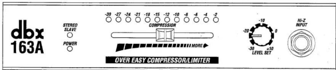
POWER LED Indicator: The red POWER indicator illuminates when AC power is applied to the unit via the AC receptacle.
STEREO SLAVE LED Indicator: The yellow STEREO SLAVE indicator indicates that the unit has been set by its rear panel switch to be the Slave in a connected pair of 163As.
Gain Reduction LEDs: These 12 LEDs display in dB how much the signal is being compressed (i.e., the amount of gain reduction).
COMPRESSION Slider: Moving this to the right (MORE) increases the amount of compression - compressing more of the signal sent to it (the compression "reaches down" to lower levels) as well as compressing the signals more (the compression ratio for any given signal level gets higher).
LEVEL SET Control: This control sets the operating (output) level that the 163A will always "aim toward" as compression is increased; the circuit automatically adjusts the gain to maintain a constant output level.
Hi-Z INPUT Jack: This jack connects to the 163A's internal low-noise FET preamp. The gain is such that virtually all low-level instruments (guitars, basses, keyboards, even some high-impedance mics) can be plugged in directly using 1/4" phone connectors. If necessary, use the rear panel Hi-Z TRIM to curb the gain of very hot instruments (e.g., some synthesizers). Note that this jack overrides the rear panel line-level INPUT.
Rear Panel

INPUT Jack: Use mono (or TRS) 1/4" phone connectors to connect this input to your line-level audio source (e.g., instrument, microphone or mixer).
OUTPUT Jack: Use mono (or TRS) 1/4" phone connectors to connect these outputs to the line inputs on your load (e.g., mixer, amplifier, etc.).
Hi-Z TRIM Control: This control sets the gain of the preamp for the Hi-Z INPUT only (see Front Panel). The gain should be normally set at +20dB (all the way right, or clockwise) unless your instrument's output is very hot. All the way left (counter-clockwise) is unity gain (0dB).
STEREO STRAPPING Jack and Switch: Connect this jack to the same jack on another 163A and you have a true RMS-detecting stereo compressor/limiter. Use TRS 1/4"stereo phone connectors only. Press the button In to set the unit as the SLAVE. For normal mono use (as well as for the stereo MASTER), leave the switch Out.
AC Cord: Plug into mains power. Note that the 163A does not have a power switch. It is recommended that the 163A be "On" at all times. Power consumption is low. If you do not plan to use the 163A for an extended period of time, unplug it.
WARNING: Be sure to verify both your actual line voltage and the voltage for which your Model

163A was wired, as indicated on the rear panel of your unit. Connection to an inappropriate power source may result in extensive damage which is not covered by the warranty.
OPERATING NOTES
Preparation/Level Adjustments
For best operation, the 163A should be reset for your application each time it's used in a different studio or with a different set of performance gear.
1. Set the LEVEL SET Control
To determine the amount of gain to add to your sound, adjust the LEVEL SET Control according to the following steps:
A. Play your instrument (or the track to be compressed) at a typical, moderate level through the 163A with the COMPRESSION Slider all the way to the left. Concentrate on how loud it sounds.
B. Move the COMPRESSION Slider all the way to the right and play the same way again (or play the same passage from the tape). Again, listen to how loud it sounds.
C. Now adjust the level by turning the LEVEL SET Control so that the volume with the slider right is the same as with the slider left.
When properly adjusted, there will be little difference in level as you move the slider, but to the right, the sound will be fatter, with more sustain, evenness, and bite to the attacks.
2. Set the COMPRESSION Slider
This is the heart of the 163A. Move the slider to the right and more of the input signal is compressed; the compression ratio is increased and more gain is added. That's why it's labeled MORE - you get more effect.
In actual use, start by playing music through the 163A with the slider to the left, then gradually move it right until you hear enough compression. Remember that dbx's OverEasy® compression curve keeps the music sounding natural even under extreme amounts of compression, so listen carefully to gauge the right amount.
3. Set the Hi-Z TRIM (if necessary)
This trim rarely requires adjustment in practical applications. It should be reset ONLY if you hear distortion (overdriving) while using the front panel Hi-Z INPUT even when the slider is all the way to the right. The instrument is probably overdriving the Hi-Z INPUT and the gain must be changed (with the TRIM).
Specific Applications
Smoothing Out Bass Guitar
Bass lines often are inconsistent in level and lack the sustain needed to give a solid bottom end. Set the MORE slider so that peaks cause 10dB to 12dB of compression. Use more for increased sustain and for more percussive attacks on the transients.
Fattening Kick Drums and Compressing Other Drum Sounds
Weak, flabby kick drums often have too much boom and not enough slap. Tighten them up by setting the slider for 15dB of compression on the peak of the kick. Because the 163A takes some time to react, this will emphasize the slap at the beginning of the note and reduce the boominess of its body. The 163A also works well for tightening snare drums and tom toms and can be used with drum machines to effectively alter the character of any electronic drum sound.
Variations in Mic Levels
The 163A works with microphones used in musical applications, paging systems, churches, speaking events, etc. As the distance between the microphone and a speaker or vocalist changes, signal levels change. Set the slider so that average levels cause 6dB to 8dB of compression, as indicated on the front meter. Use more for less-experienced speakers or vocalists. Ask them to help out by backing off on the mic a bit when speaking louder or singing especially loud notes.
Variations in Instrument Levels
To smooth out instrument levels, set the slider so that 8dB or more of compression occurs on all peaks. Be careful, however: large amounts of compression used on a mixed stereo program can become quite audible. Compression is much less noticeable if the separate tracks are compressed before mixing.
Raising the Signal Out of a Mix
Since reducing dynamic range can increase the average signal level and meter readings, a single track can be brought up out of a mix by boosting its level slightly and applying compression. Set the slider for 4dB to 6dB.
Preventing Sound System Overload
To get the benefits of the Infinity:1 part of the compression curve to prevent sound system overload (whether you're doing auditorium, church, or club sound engineering, or are a mobile DJ for small dances), set the slider to provide 15 or more dB of compression just a few dB below the input clip. For low-level signals, the 163A won't change gain, but if large signals come along, the gain will be reduced to prevent clipping and save sensitive system components from damage.
As a rule, to give the best protection, your 163A should be as close as possible in the signal path to the power amp. For maximum SPLs (watch your ears), large sound-reinforcement systems frequently have a separate compressor on each output of the electronic crossover.
CONNECTING THE 163A TO YOUR SYSETM
Basic Connection
The 163A can be connected for basic operation as shown in Figure 2.
For more specific installation information, refer to Installation Considerations, page 10.
Rear Panel INPUT
Use the rear panel (line) INPUT in recording when the instrument to be compressed is already preamplified, such as through a direct box or console. Synthesizers sometimes can plug in here, too. And of course, when mixing or submixing (e.g., to open up a track in a crowded tape), the signal from the deck (or console/mixer) goes here.
In live performance, this input is again useful for connection to synthesizer high-level outputs or line-level outputs of guitar and bass preamps (before the feed to the power amp). It can also be inserted into the effects loop on a guitar or bass amp if being used primarily to achieve more sustain.
Front Panel Hi-Z INPUT
Use the front panel H-Z INPUT in the studio for adding quick (direct input) overdubs, and for the convenience of carrying the guitar or bass into the control room (no hassle of lugging an amp). In performance, any instrument can plug directly into this input (synths included), as well as many high-impedance microphones.
For all connections, refer to the following steps:
A. Turn Off all equipment before making any connections. (Disconnect the 163A from AC power.)
B. Make connections via 1/4" phone jacks according to your requirements.
C. Set the rear panel MASTER/SLAVE Button to MASTER (Button not depressed).
D. Plug in the AC power cable to power On the unit.

flowchart
graph LR
    A["INSTRUMENT, MIC, MIXER GUITAR AMP EFFECTS LOOP"] -->|OUTPUT| B["MIXER, AMPLIFIER"]
    C["AUDIO SOURCE"] -->|OUTPUT| B
    D["REAR PANEL INPUT OR FRONT PANEL HI-Z INPUT"] -->|OUTPUT| B
    E["DBX PROFESSIONAL PRODUCTS A HAWMAN INTERNATIONAL COMPANY SALT LAKE CITY, UTAH MADE IN USA ALL CIRCUIT DESIGNS ID IN THE YEARS 1979-1988 US PATENTS 3,681,618 4,400,198 3,714,482 4,409,500 4,687,767 4,426,581 3,786,143 3,377,792 4,329,589 4,473,766 4,101,849 4,109,314"] -->|120 V ~ 82/60 Hz 18 WATTS| E
Figure 2: Basic Connection
INSTALLATION CONSIDERATIONS
Stereo Operation
Stereo strapping is essential for all applications where two channels must be compressed and the left/right perspective remain the same. Examples include the L and R overhead mics on a drum kit or piano, a stereo submix of a vocal ensemble, the feed from an X-Y or other pair of mics in a classical recording, a complete stereo mix, etc.
When the rear panel MASTER/SLAVE switches are properly set and the stereo cable connected, the gain changes in the two channels will be identical. The signals at each RMS detector are combined (so the true RMS sum can be sensed) and controlled. All functions of the Master unit control both channels.
To connect two 163As together for stereo operation:
A. Turn Off all equipment before making any connections. (Disconnect both 163As from AC power.)
B. Connect a TRS 1/4" stereo phone plug to the STEREO STRAPPING jacks of each unit. Note that 1/4" mono plugs will not work here.
C. Determine which unit is the Slave; press in the MASTER/SLAVE switch located on the unit's rear panel. The yellow SLAVE LED on the front of the unit will illuminate.
D. Plug in the AC power cables to power On the units.
NOTE: For dual mono operation - when you want to have two independent compressors - you have to remove the cable attached to the STEREO STRAPPING jacks, if any, and leave both MASTER buttons Out.
INSTALLATION CONSIDERATIONS
Mounting the 163A in a 1U Rack Space
The 163A requires one rack space (height) and 1/2 rack space (width). It can be mounted above or below anything that doesn't generate excessive heat, since it requires no special ventilation. Ambient temperatures should not exceed 113^ (45^) when equipment is powered. Hardware for mounting your 163A is provided in the Accessory Kit (optional) of the 163A package.
To save rack space, two 163A units may be mounted side-by-side. In addition, the 163A can be mounted next to other dbx "half-rack" units. Hardware for side-by-side mounting is included in the optional accessory kit. If the rubber feet were used for tabletop operation, they should be removed at this time.

Caution: Never remove the cover. There are no user-serviceable parts inside, and you run the risk of an electric shock.
To install a single 163A (left or right side)

Figure 3: Rack Mounting One 163A Unit
You will need:
1 blank black panel
1 rack ear
1 blank panel adaptor piece
1 3/32" Allen wrench
1 Phillips screwdriver (not included)
4 pan head Phillips screws
2 hex head screws
NOTE: The (OPTIONAL) Accessory Kit includes the tools and hardware listed above, except as noted.
A. Use a Phillips screwdriver to loosely attach the single rack ear to either side of the 163A with two pan head Phillips screws.
NOTE: If this is the first time the rack ear has been installed, you will be cutting threads as you drive the screws. This is normal.
B. Loosely attach the adaptor piece to the other side of the 163A using two more pan head Phillips screws and a Phillips screwdriver. See note above.
C. Loosely attach the blank panel and adaptor piece using an Allen wrench and two hex head screws.
D. Align everything on a flat surface and tighten the screws with a Phillips screwdriver and the hex wrench.
To install two units side-by-side

Figure 4: Rack Mounting Two 163A Units
| You will need: | 1 | joiner assembly( joiner, joiner side pieces) |
| 1 | reinforcing plate | |
| 2 | rack ears | |
| 1 | 3/32" Allen wrench | |
| 1 | Phillips screwdriver (not included) | |
| 4 | pan head Phillips screws | |
| 4 | flat head countersink screws |
NOTE: The (OPTIONAL) Accessory Kit includes the tools and hardware listed above, except as noted.
A. Remove the joiner assembly from the Accessory Kit that was supplied with each unit. Note how the joiner side pieces are held captive by the joiner before you separate them. This is important when it comes time to join the units together. Now separate the joiner side pieces from the joiner by turning the thumbscrew counterclockwise.
B. At this time you will need to designate a "Left" and a "Right" unit.
C. With the left unit facing you, loosely attach a rack ear to the left side of the unit with two pan head Phillips screws. On the right side of the unit, place a joiner side piece into the extruded channel so the holes in the unit align with the holes in the joiner side piece - countersink side up. Secure the joiner side piece with two countersink screws.
NOTE: If this is the first time the rack ear has been installed, you will be cutting threads as you drive the screws. This is normal.
D. Repeat step C with the "Right" unit; swapping right for left with regard to the rack ear mounting and left for right with regard to the joiner side piece mounting.
E. Place the Left and Right units on a flat surface, rear facing, so the joiner side pieces are approximately 2" apart. Take the joiner assembly and loosen the thumbscrew so the sliding catches clear the joiner side-piece cut-outs. Now place the joiner assembly against one of the units with the side piece so it lays flush. (The joiner assembly should be positioned so the thumbscrew is accessible from the rear of the unit.) While holding the joiner assembly in posi
tion, slide the other unit over so it mates flush with the joiner assembly and turn the thumb-screw clockwise until it is snug. Do not over-tighten. Both units should now be secured together.
F. Make sure everything is aligned, and tighten the screws on each of the two rack ears.
NOTE: For installations where the two units will be subjected to physical stress (e.g. portable operations), a small OPTIONAL reinforcement plate is included. See steps G through I. If you don't wish to use the reinforcing plate, skip the following steps.
G. Turn the two units so that the back faces you. Remove the four rear cover screws nearest the joiner knob.
H. Place the reinforcing plate over the joiner knob so that the four screw holes line up.
I. Replace the four screws, using the slightly longer screws provided in the Accessory Kit.
Input/Output Cable Configurations
Hookups and Cabling
The 163A is an unbalanced unit designed for nominal levels from -10dBV to +4dBu; inputs and outputs are 1/4" phone jacks. The 163A can be used with either balanced or unbalanced sources and outputs can be used with either balanced or unbalanced loads, provided you use proper cabling.
A balanced line is defined as two-conductor shielded cable with the two center conductors carrying the same signal but of opposite polarity with respect to ground. An unbalanced line is generally a single-conductor shielded cable with the center conductor carrying the signal and the shield at ground potential.
Connect Audio Inputs
Figure 5 shows cables for connecting a signal source to the 163A.
Both the rear panel INPUT and front panel Hi-Z INPUT are unbalanced. The input impedances are 391kΩ unbalanced, allowing operation from virtually any source. The adjustable Hi-Z INPUT can be set for levels ranging from -28dBu to +12dBu. The input connectors are 1/4" phone jacks.
Output Cable Configurations
Figure 5 shows cables for connecting the 163A audio OUTPUT to balanced and unbalanced loads. Refer to the type of operation and type of connector you are using.
The 163A will drive either balanced or unbalanced loads with unbalanced signal as long as the cables are wired as shown below in Figure 5.
All outputs are unbalanced for driving loads of 600Ω or greater. Maximum output level is +18dBu. Output impedance is 22Ω unbalanced. The output jacks are 1/4" phone jacks.
NOTE: For best hum rejection, start by grounding the shield(s) [Pin 1 on the XLR, Sleeve on a 1/4" TRS only at the output(s). If hum persists, try grounding the shield(s) at the input(s) as well.
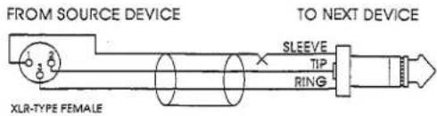
FEMALE XLR-TYPE TO STEREO PHONE PLUG
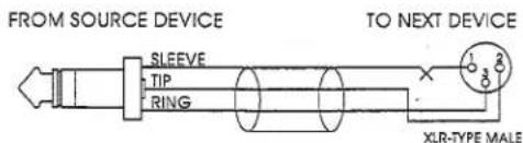
STEREO PHONE PLUG TO MALE XLR-TYPE

STEREO PHONE PLUG TO STEREO PHONE PLUG
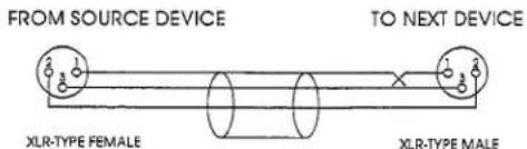
FEMALE XLR-TYPE TO MALE XLR-TYPE
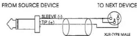
MONO PHONE PLUG TO MALE XLR-TYPE

MONO PHONE PLUG TO STEREO PHONE PLUG

RCAI PHONO PLUG TO MALE XLR-TYPE

PHONO PLUG TO STEREO PHONE PLUG

flowchart
graph LR
    A["FROM SOURCE DEVICE"] --> B["SLEEVE (-) TIP (+)"]
    B --> C["SLEEVE (-) TIP (+)"]
    C --> D["TO NEXT DEVICE"]
MONO PHONE PLUG TO MONO PHONE PLUG

PHONO PLUG TO MONO PHONE PLUG

STEREO PHONE PLUG TO MONO PHONE PLUG

MONO PHONE PLUG TO PHONO PLUG
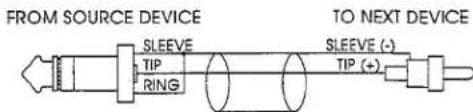
PHONO PLUG TO MALE XLR-TYPE
Figure 5: Input and Output Connections
Connecting Power
A. Check the line voltage.
The 163A is shipped for 100V, 120V, 230V, or 240V, 50Hz or 60Hz operation. Refer to the unit's rear panel to verify your unit's precise line voltage.
B. Connect the 163A's power cord to an appropriate AC power source.
TECHNICAL SUPPORT, FACTORY SERVICE
The 163A is an all-solid-state product with components chosen for high performance and excellent reliability. Each 163A is tested, burned in and calibrated at the factory and should require no internal adjustment of any type throughout the life of the unit.
Technical Support
If you require technical support, contact dbx Customer Service. Be prepared to accurately describe the problem. Know the serial number of your unit - this is printed on a sticker attached to the rear panel.
Telephone: (1) 801/568-7660
or Write:
dbx Professional Products
or Fax: (1) 801/568-7662
a Harman International Company
8760 Sandy Parkway
Sandy, Utah 84070 USA
ATTN: Customer Service
Factory Service
Before you return a product for service, we recommend you refer to the manual. Make sure you have correctly followed installation steps and operation procedures. If you are still unable to solve a problem, contact our Customer Service Department for consultation. Often, a problem is relatively simple and can be quickly fixed after telephone consultation. If you need to return a product to the factory for service, include a letter describing the problem.
Please refer to the terms of your Limited Two-Year Standard Warranty, which extends to the first end-user. After expiration of the warranty, a reasonable charge will be made for parts, labor, and packing if you choose to use the factory service facility. In all cases, you are responsible for transportation charges to the factory. dbx will pay return shipping if the unit is still under warranty.
Use the original packing material if it is available. Mark the package with the name of the shipper, and with these words in red:
DELICATE INSTRUMENT, FRAGILE!
Insure the package properly. Ship prepaid, not collect. Do not ship parcel post.
SPECIFICATIONS
| (NOTE: 0dBV = 1.0VRMS; 0dBu = 0.775VRMS) | Specifications are subject to change. |
| Frequency Response, | 20Hz - 20kHz; ±1.0dB |
| Input | |
| Front Panel | Instrument, Unbalanced: 391kΩ |
| Maximum Input Level | +18dBu |
| Connector Type | 1/4" Phone Jack |
| Rear Panel | Instrument, Unbalanced: 391kΩ |
| Maximum Input Level | +18dBu |
| Connector Type | 1/4" Phone Jack |
| Output | |
| Rear Panel | Unbalanced: 22Ω |
| Minimum Load Impedance | ≥600Ω |
| Maximum Output Level | +18dBu into 600Ω |
| Connector Type | 1/4" TRS Phone Jack |
| Distortion | |
| THD | <0.2%, Any amount of compression @ 1kHz,-10dBv, 10-30 kHz Bandwidth |
| IMD | <0.2%, Any amount of compression, SMPTE |
| Equivalent Input Noise | -85dBu, Unweighted |
| Dynamic Range | 103dB |
| Gain Adjustment (Level Matching) | Automatic, depending on MORE Slider; Additional 0 - 20dB Adjustable Instrument Input |
| Attack Time | Program Dependent; 15ms for 10dB, 5ms for 20dB, 3ms for 30dB |
| Release Time | Program Dependent; 0 - 400ms, 8ms for 1dB, 80ms for 10dB,400ms for 50dB, 125dB/sec Rate |
| Threshold Range | -30 to +10dBu |
| Threshold Characteristic | OverEasy® |
| Compression Ratio | 1:1 to Infinity:1, >50dB Maximum Compression |
| Operating Voltage | 100VAC, 120VAC,230VAC, 240VAC, 50/60Hz |
| Operating Temperature | 0°C to 45°C (32°F to 113°F) |
| Dimensions (H x W x D) | 1.75" x 8.5" x 7.25" (4.45cm x 21.59cm x 18.42cm) |
| Rack Space | 1/2 Rack Unit (1U High) |
| Weight | Net Weight: 2.5 lbs (1.1 kg)Shipping Weight: 5 lbs (2.3 kg) |
| Warranty | dbx standard two-year warranty |

- MODEL 163A
- Over Easy® COMPRESSOR/LIMITER
- CAUTION
- MANUAL CONTENTS
- INTRODUCTION
- INSPECTION
- Verify that the 163A package contains the following:
- QUICK SETUP
- WARRANTY
- UNDERSTANDING COMPRESSION
- Compression
- About The 163A Circuit
- OPERATING CONTROLS
- OPERATING NOTES
- Preparation/Level Adjustments
- Set the LEVEL SET Control
- Set the COMPRESSION Slider
- Set the Hi-Z TRIM (if necessary)
- Specific Applications
- Smoothing Out Bass Guitar
- Fattening Kick Drums and Compressing Other Drum Sounds
- Variations in Mic Levels
- Variations in Instrument Levels
- Raising the Signal Out of a Mix
- Preventing Sound System Overload
- CONNECTING THE 163A TO YOUR SYSETM
- Basic Connection
- Rear Panel INPUT
- Front Panel Hi-Z INPUT
- INSTALLATION CONSIDERATIONS
- Stereo Operation
- Mounting the 163A in a 1U Rack Space
- To install a single 163A (left or right side)
- Input/Output Cable Configurations
- Hookups and Cabling
- Connect Audio Inputs
- Output Cable Configurations
- Figure 5: Input and Output Connections
- TECHNICAL SUPPORT, FACTORY SERVICE
- Technical Support
- Factory Service
- DELICATE INSTRUMENT, FRAGILE!
Marque : DBX
Modèle : 163A
Catégorie : Compresseur audio