
85745188 - Téléviseur HAGER - Notice d'utilisation et mode d'emploi gratuit
Retrouvez gratuitement la notice de l'appareil 85745188 HAGER au format PDF.


| Type de produit | Appareil électrique modulaire |
| Marque | Hager |
| Modèle | 85745188 |
| Tension nominale | 230 V AC |
| Courant nominal | 16 A |
| Nombre de pôles | 1 |
| Dimensions (L x H x P) | 18 x 85 x 70 mm |
| Poids | 0,15 kg |
| Alimentation | Réseau monophasé |
| Fréquence | 50 Hz |
| Pouvoir de coupure | 6 kA |
| Fonctions principales | Protection contre les surcharges et les courts-circuits |
| Entretien et nettoyage | Dépoussiérer avec un chiffon sec, ne pas utiliser de produits chimiques |
| Sécurité | Installation par un électricien qualifié, respect des normes en vigueur |
| Pièces détachées et réparabilité | Non réparable par l'utilisateur, remplacer en cas de défaut |
| Informations générales | Conforme aux normes CE, à utiliser en intérieur |
FOIRE AUX QUESTIONS - 85745188 HAGER
Questions des utilisateurs sur 85745188 HAGER
0 question sur cet appareil. Repondez a celles que vous connaissez ou posez la votre.
Poser une nouvelle question sur cet appareil
Téléchargez la notice de votre Téléviseur au format PDF gratuitement ! Retrouvez votre notice 85745188 - HAGER et reprennez votre appareil électronique en main. Sur cette page sont publiés tous les documents nécessaires à l'utilisation de votre appareil 85745188 de la marque HAGER.
MODE D'EMPLOI 85745188 HAGER
Operation and installation instructions
[Non-Text]

KNX radio shutter timer quicklink
[Non-Text]
[Non-Text]
[Non-Text]
[Non-Text]
[Non-Text]
GB
Berker GmbH & Co. KG Zum Cuaterstol
Zum Gunnerstor 66440 Blieskastel/Germany
Tel.: +49 6842 945 0
ax: +49 6642 945 4625 E-Mail: info@berker.de
- 2017年1月1日
www.berker.com

[Non-Text]
05/2022
6LE008541A

[Non-Text]
[Non-Text]
[Non-Text]
[Non-Text]
[Non-Text]
[Non-Text]
[Non-Text]
[Non-Text]
[Non-Text]
[Non-Text]
[Non-Text]
[Non-Text]
[Non-Text]
[Non-Text]
[Non-Text]
[Non-Text]
[Non-Text]
[Non-Text]
[Non-Text]
[Non-Text]
[Non-Text]
[Non-Text]
[Non-Text]
[Non-Text]
[Non-Text]
[Non-Text]
[Non-Text]
[Non-Text]
[Non-Text]
[Non-Text]
KNX Radio shutter timer quicklink
Safety instructions
Electrical equipment must only be installed and assembled by a qualified electrician in a
and assembled by a qualified electrician in accordance with the relevant installation stan-
dards, regulations, directives and safety and
accident prevention directives of the country
Failure to comply with these installation instructions may result in damage to the device
fire or other hazards.
The radio transmission is not suitable for saf
ty or alarm applications.
These instructions are an integral component of the product, and must be retained by the
end user
Design of
Design of the device (2)
(3)
- 2017年1月1日
(4)
- 2017年1月1日
图 1
(5)
90
(6) (7)
(1)
Figure 1: Design of the device
(1) Insert (see „Accessories“, not in scope of
delivery)
(2) Frame (not in scope of delivery) (3) Application module
(3) Applicai (4) Display
(4) Display (5) Design cover
(6) Screw for dis
design lines R.1/R.3)
(7) Operation buttons
Function
This device
which installation devices communicate via radio
signals.
quicklink stands for a configuration mode in which the function-related connection between trans-
the function related connection between transmitters and receivers is set on the device through
push-buttons and displays without further tools.
All devices configurable by quicklink can be operated together in one system.
This device is compliant to the R&TTE-Directive
1999/5/EG. The Declaration of Conformity and
further system information can be found on our homepage www.berker.de
The device may be used in all EU and EFTA
the down countries.
Correct use
- Applicatie
- Application module for smaller insert of power supply for radio application modules
- Manual, time-controlled and automatic operati
on of blind/shutter motors connected to insert
- Transmission and reception of manual, time-controlled and automatic operation commands
via quicklink
- Unsuitable for lighting control
- Only suitable for use in indoor areas, no drip or
spray water
The quicklink configuration of the devices must only be carried out by qualified electricians.
(1)
Product characteristics
- quicklink functions for integration into the remote and group control of blinds/shutters.
- Integration into scenes
- Two preset standard time programmes, individually adjustable
- Astro progr
Astro programme for automatic operation at dawn/dusk
- Astro time s
- Holiday programme for random operation time
in automatic
- Party programme to prevent unintentional operation of the shutters by automated operation
commands as well as radio/extension unit com
mands
- Keylock Automatic switching to standard/daylight setting
• Automatic switching to standard/daynight savings time
- Brightness-
radio sun sensor
performance after mains breakdown/return of
nains supply
- Mains breakdown
Saving of the current configuration and programming in the non-volatile memory. The de-
gramming in vice then sw
internal clock continues to run to keep the time up to date. The use of a buffer memory on
up-to-date. The use of a buffer memory ensures that the time stays up-to-date for up to 2+
hours.
- Return of mains supply
The application module executes an implementation operation ^1 , the basic display is restored.
The stored configuration and programming is
loaded from the memory. Any operations pen- ding when the power supply broke down will
ing within the power supply brows down will not be executed after return of mains supply.
If the buffer memory is full, date and time must be entered again.
entered again
Operation
operating concept and display elements
When controlling the shutter, the buttons (Fig. 2)
istinguish between a short press and a long pres
r > 0.5 second
nessing the button for >2 seconds can trigger arious functions within the menu operation.
the current clock status is shown in the display.
active functions are displayed by using symbols
Table 1). Display illumination is activated for as soon as a button is pressed.
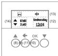
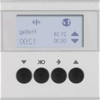
Figure 2: Display and operating elements
3) UP button ▲
3) Back button ◆
10) OK button
(1) DOWN button ▼ (2) Display area for
12) Display area for weekday and time
(13) Display area for active functions/programming (14) Display area for the next operation times
(14) Display area for the next operation times
Symbol Function
The image is too blurry to recognize any text content.
- Manual script
己
D1 D2
1
m = 311
④
|
m = 311
Y
|
1
m = 311
|
m = 311
m = 311
m = 311
m = 311
m = 311
|
m = 311
m = 311
C
[Non-Text]
[Non-Text]
[Non-Text]
[Non-Text]
[Non-Text]
[Non-Text]
[Non-Text]
[Non-Text]
[Non-Text]
[Non-Text]
[Non-Text]
m = 311
-
[Non-Text]
[Non-Text]
[Non-Text]
[Non-Text]
[Non-Text]
[Non-Text]
[Non-Text]
[Non-Text]
[Non-Text]
[Non-Text]
[Non-Text]
[Non-Text]
[Non-Text]
[Non-Text]
[Non-Text]
[Non-Text]
[Non-Text]
[Non-Text]
[Non-Text]
[Non-Text]
[Non-Text]
[Non-Text]
[Non-Text]
[Non-Text]
[Non-Text]
[Non-Text]
[Non-Text]
[Non-Text]
[Non-Text]
[Non-Text]
[Non-Text]
[Non-Text]
[Non-Text]
[Non-Text]
[Non-Text]
[Non-Text]
[Non-Text]
[Non-Text]
[Non-Text]
[Non-Text]
[Non-Text]
[Non-Text]
[Non-Text]
[Non-Text]
[Non-Text]
[Non-Text]
[Non-Text]
[Non-Text]
[Non-Text]
[Non-Text]
[Non-Text]
[Non-Text]
[Non-Text]
[Non-Text]
[Non-Text]
[Non-Text]
[Non-Text]
[Non-Text]
[Non-Text]
[Non-Text]
[Non-Text]
[Non-Text]
[Non-Text]
[Non-Text]
[Non-Text]
[Non-Text]
[Non-Text]
[Non-Text]
[Non-Text]
[Non-Text]
[Non-Text]
[Non-Text]
[Non-Text]
[Non-Text]
[Non-Text]
[Non-Text]
[Non-Text]
[Non-Text]
[Non-Text]
[Non-Text]
[Non-Text]
[Non-Text]
[Non-Text]
[Non-Text]
[Non-Text]
[Non-Text]
[Non-Text]
[Non-Text]
[Non-Text]
[Non-Text]
[Non-Text]
[Non-Text]
[Non-Text]
[Non-Text]
[Non-Text]
[Non-Text]
[Non-Text]
[Non-Text]
[Non-Text]
[Non-Text]
[Non-Text]
[Non-Text]
[Non-Text]
[Non-Text]
[Non-Text]
[Non-Text]
[Non-Text]
[Non-Text]
[Non-Text]
[Non-Text]
[Non-Text]
■ Set the location and times (see Setting values). Run through all the setting options. Having confirmed the latest down time time, a
query is displayed.

■ Press the buttons ▲ or ▼ to select the required option and confirm by pressing OK.
Yes: The screen switches to the basic display.
The Astro programme is run and the symbol ⑦
is displayed (Figure 2, 13). The Astro settings are saved and Astro is added to the programme
are saved and Astro is added to the programme selection (Fig. 4, 18).
No: The screen switches to the basic display.
The Astro settings are saved and astro mode
is added to the programme selection (Fig. 4,
18) but is not run.
- 2017年1月1日
Submenu A8 - Set display contrast
In the submenu advanced settings (Fig. 4, 23),
splay settings is highlighted dark.
Short press on OK button.
The current contrast value as an active element
is highlighted dark.
result

■ Set the location and times (see Setting values). Having made the setting, the display returns to the Basic setting submenu.
Submenu A9 - Resetting the device to the
factory settings
In the factory setting, both the user's settings
in the factory setting, both the user's settings such as programmes or Astro settings, are re
such as programmes of Audio settings, are to set and all the configured radio logic function
deleted.
In the submenu advanced settings (Fig. 4, 23),
factory settings is highlighted dark.
■ Press the OK button for more than 10 seconds.
During initialisation, the display shows ⊙ and
then switches to Start-up mode. Language,
time and date must be reset.
Information for electricians
Installation
Installation
Selecting installation location
A minimum distance between the transmitter and
corresponding receiver of about 1 m must be
maintained.
A minimum distance to electronic devices which
emit high frequency signals such as computers,
electronic transformers or microwave devices of
approx. 0.5 m must be maintained.
Mounting on or close to metal surfaces may cause
impairment of the radio transmission.
Take material penetration into account. The range
of the system can be optimised by selecting the best possible mounting location.
best possible mounting location:
Material Degree of motori
Material Degree of material penetration
Wind, polyester, plasticboard paper: 90%
Wood, plaster, plasterboard, approx. 90 %
uncoated glass
Brick, press boards approx. 10%
Reinforced concrete, floor approx. 30 %
heating
Metal, metal grids, alumini- approx. 10 %
um laminates, coated glass
Rain, snow approx. 1 ... 40 %
Table 7: Mr
TABLE 2. Mr
of the devi
is installed (
ert).
the applicati
2) to a suit
: pins are ins
n as voltage
dule, the dis
tion module
each other;
12
y text Mean
ating
indicator)
Power
e N
Ir
or de" Boxers
| Reactive Power Module! | Insert and replace as necessary. |
| Changed Power Module / Reset to factory? | Compatible, but not conti gu-red to each other.Direct reset of the radio confi guration to the factory setting possible by kee-ping (10 s) the OK button pressed.User settings (e.g. times, programmes) remain set. |
Table 3: Insert/application module compatibility
■ If available, fi x dismantling protection with
screw (4).
■ Click design cover (5 or 6) into place on appli
cation module (3).
[Non-Text]
Start-up
First author:
First start-up
The device initialises itself when the mains voltage
is switched on for the first time. Insert detection is carried out and if an incompatible device is
is carried out and, if an incompatible device is found, a message is displayed (see Table 2). Then
found, a message is displayed (see Table 3). Then an hourglass and the manufacturer's logo are
displayed
The language selection is displayed, the first lan-
guage is high
lighted dark.
•
Deutsch
English
Français
The Ground Truth image displays a single, solid horizontal line. According to Rule 2 (UNDERSCORE & LINE RULES), if the GT contains lines used for stylistic emphasis or as background (like ruled paper), the OCR result must ignore them. The provided OCR content is "____", which consists of four underscores. This is incorrect because underscores are not equivalent to a solid line and are not permitted under the “Stylistic/Background Lines (Ignore)” rule. Outputting underscores for a stylistic line violates the rule and constitutes an error. Therefore, the OCR result is inconsistent with the Ground Truth.
age, time and date (see
[Non-Text]
e switches to the basic display and is
operation.
A
[0]
Wednesday
12:06
-
While the basic display is displayed, the opera-
ting mode can be changed up to 30 s after de-
lecting the insert at the latest if necessary (see Setting Ordering Mode).
Setting Operating Mode
Setting Operating Mode
It is possible to change between two operating
It is possible to change between two operating modes during the first 30 s of the commissioning:
Protection Mode (system setting):
- Protection mode (factory setting). Mode for using sensors on the extension unit
inputs of the insert to protect against wind or
rain damage on outside blinds/lawnings.
In protection mode no move commands are
in protection meets the more commitments and executed while a signal (wind /rain sensor) is
the extension unit input
ode:
200.
ether or not it takes place locally or
ension unit.
play is displayed.
■ Hold button ▲ and ▼ simultaneously for an-
- Hold button ▲ and √ simultaneously for up prox. 5 s until the display chances.
The operating mode is changed and displayed
This operating mode is changed and displayed. Priority extension line up enabled display
Priority extension line up enabled display: The protection mode is set
The protection mode is set.
(二) A =
extension line up disabled display:
al mode is set.
operation, the operating mode can no
changed and displayed after 30 s
ed.
[Non-Text]
[Non-Text]
[Non-Text]
Submenu E1 - Radio configuration
quicklink
The index is
The radio configuration sets the functional connection between commanding (transmitters) and
function between commanding (parameters) and function-executing (receivers) radio components
Thus wireless e.g. central unit, group, extension
unit and time controls can be realised.
The following can be configured:
- The local operation of the load connected to
the insert
- Radio commands to control other receivers.
- Radio commands to control other receivers Functions that are expected when radio cars
- Functions that are executed when radio commands are received.
mands at
For configuration by means of Hager connec
tion device TX100 or ETS, additional function
are available (see operating instructions for TX100 or application description for ETS)
TX-100 of application description for ETO).
Configuring the radio shutter timer as a
receiver
Confi auratic
insert via reception of a radio command (Table 4
As an example, the configuration of a wall-trans
mitter and the radio shutter timer as receiver is
described down below (Table 5).
If the message Connection error is displayed
- This message communication error is displayed during configuration, this indicates an impose
ble comb
by pressi
(No text)
The Ground Truth image displays a single, solid horizontal line. According to Rule 2 (UNDERSCORE & LINE RULES), this is a stylistic or background line, not a placeholder underscore. Therefore, the OCR result must ignore it and output nothing or only meaningful text. The provided OCR content is "____", which consists of four underscores. This is an incorrect interpretation of the line as a placeholder, violating the rule that stylistic lines must be ignored. The OCR has hallucinated underscores where none should exist based on the GT's visual context. Hence, the OCR result is inconsistent with the Ground Truth.
link error
m = 311
(No text)
uring the radio
itter
owing radio com
r functions is sup
12/08/11
IP/DOWN (SWIB)
the device is con on of a compatib
re assigned using
he device serves as a master. Active shut
er timer programmes are also run on the
receivers.
As an example, the configuration of the radio shut
ter timer with a radio shutter push-button is shown
here (Table 6). Different configuration displays,
such as for receivers with display, are to be taken
from the receiver operating instructions
Deleting a configuration
To delete a configured receiver or the local operati
To address a configuration receiver of the latest operation, execute the configuration again.
■ Start configuration /see configuration of the
■ Start configuration (data configuration of the radio shutter timer as a receiver).
■ If necessary. Select transmitter b
■ If necessary, select transmitters:
If the radio shutter push-button functions as a
transmitter, the step Select transmitter button does not apply.
■ Select function
■ Select function on receiver.
(No text)
Step
Start configuration
■ Short press on cfg button
transmitter.
W-34 1987
(2) _i (1)
[Unreadable]
[Non-Text]
(6)
If there is no further initiative
- If there is no further activation, it is automatically ended after
15 automatically closed and
Caled trans-Web button
Select transatlnter busc)
■ Short press on press-activ
wall-transmitter which shows function
- 2017
(2) 100%
-
-
-
-
-
-
-
-
-
-
-
-
-
-
-
-
-
-
-
-
-
-
-
-
-
-
-
-
-
-
-
-
-
-
-
-
-
-
-
-
-
-
-
-
-
-
-
-
-
-
-
-
-
-
-
-
-
-
-
-
-
-
-
-
-
-
-
-
-
-
-
-
-
-
-
-
-
-
-
-
-
-
-
-
-
-
-
-
-
-
-
-
-
-
-
-
-
- 99.
-
-
-
-
-
-
-
-
-
-
-
-
-
-
-
-
-
-
-
-
-
-
-
-
-
-
-
-
-
-
-
-
-
-
-
-
-
-
-
-
-
-
-
-
-
-
-
-
-
-
-
-
-
-
-
-
-
-
-
-
-
-
-
-
-
-
-
-
-
-
-
-
-
-
-
-
-
-
-
-
-
-
-
-
-
-
-
-
-
-
-
-
-
-
-
-
[图]
1
[Non-Text]
Select function on receiver
■ Open the quicklink setting
- Open the quicklink set in the menu and navigating).
red setting
astro settings display settings
display servings
(3) 2016年1月1日
■ Press the buttons ▲ or ▼
quicklink function and co
OK.
configuration
| 2014-03-27
select quicklink
(1)
(No text)
(No text)
■ Conf i rm the function on the receiver: press the
▲ or ▼ button, select delete and confirm with
OK.
An hourglass displays the logic function
operation. The successful deletion of the logic
function is then displayed.
(2)
link deleting
| | successful
The image contains two horizontal lines, which are stylistic or background elements. According to Rule 2, such elements must be ignored by the OCR result. Therefore, the corrected OCR text is:
[Empty String]
The Ground Truth image displays a single, solid horizontal line. According to Rule 2 (UNDERSCORE & LINE RULES), this is a stylistic or background line, not a placeholder underscore. Therefore, the OCR result must ignore it and output nothing or only meaningful text. The provided OCR content is "____", which consists of four underscores. This is an incorrect interpretation of the line as a placeholder, violating the rule that stylistic lines must be ignored. The OCR has hallucinated placeholder underscores where none should exist in the GT. Hence, the OCR result is inconsistent with the Ground Truth.
This image contains no text. The visible element is a stylistic or background line, which must be ignored according to the rules.
result
m = 311
The cfg LED on the wall-transmitter blinks red.
Cfg (Table 1) is shown in the display of the shutter
mer.
请以“”
Cfa
Friday
12:13
(1)
(二) 本
all receivers within radio range also indicate the
drill duration mode.
2.1.1.2023年1月1日(星期五)
he ctg LED on the wall transmitter blinks for 1
second.
海三五
[Figure 1]
图1|中 |
1
(1)
(二)本年利润
The Ground Truth image displays a single, solid horizontal line. According to Rule 2 (UNDERSCORE & LINE RULES), this is a stylistic or background line, not a placeholder underscore. Therefore, the OCR result must ignore it and output nothing or only meaningful text. The provided OCR content is "____", which consists of four underscores. This is an incorrect interpretation of the line as a placeholder, violating the rule that stylistic lines must be ignored. The OCR has hallucinated underscores where none should exist based on the GT's visual context. Hence, the OCR result is inconsistent with the Ground Truth.
The Ground Truth image displays a single, solid horizontal line. According to Rule 2 (UNDERSCORE & LINE RULES), if the GT contains lines used for stylistic emphasis or as background elements (like ruled paper), the OCR result must ignore them. The provided OCR content is "____", which consists of four underscores. This is incorrect because underscores are not equivalent to a solid line and are not permitted under the “Stylistic/Background Lines (Ignore)” rule. The OCR has hallucinated underscores where none should exist in the GT, violating the “Stylistic/Background Lines (Ignore)” rule. Therefore, the OCR result is inconsistent with the Ground Truth.
configuration
select adviklin
function
The Ground Truth image displays a single, solid horizontal line. According to Rule 2 (UNDERSCORE & LINE RULES), this is a stylistic or background line, not a placeholder underscore. Therefore, the OCR result must ignore it and output nothing or only meaningful text. The provided OCR content is "____", which consists of four underscores. This is an incorrect interpretation of the line as a placeholder, violating the rule that stylistic lines must be ignored. The OCR has hallucinated placeholder underscores where none should exist in the GT. Hence, the OCR result is inconsistent with the Ground Truth.
The Ground Truth image displays a single, solid horizontal line. According to Rule 2 (UNDERSCORE & LINE RULES), this is a stylistic or background line, not a placeholder underscore. Therefore, the OCR result must ignore it and output nothing or only meaningful text. The provided OCR content is "____", which consists of four underscores. This is an incorrect interpretation of the line as a placeholder, violating the rule that stylistic lines must be ignored. The OCR has hallucinated underscores where none should exist based on the GT's visual context. Hence, the OCR result is inconsistent with the Ground Truth.
a list of possible functions is displayed.
•
Up
cove
Screw 1
If the transmitter button has already been
configured with a function in a different receiver
and/or the configured function is part of a group
control, only this function can be configured.
To change a function, the existing configuration
must be deleted and the new one needs to be
conti gured.
2、交易对方:徐志华、徐志华、徐志华、徐志华
An hourglass displays the logic function operation.
The successful execution of the configuration is
len displayed.
□ | 1458
→ 2014.1.2015 successful
- | |
The wishfish setting was deployed. The ②
the quicklink setting menu is displayed. The symbol indicates that a logic function was set up

Marque : HAGER
Modèle : 85745188
Catégorie : Téléviseur