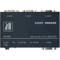
VP-14 - Répartiteur Kramer - Notice d'utilisation et mode d'emploi gratuit
Retrouvez gratuitement la notice de l'appareil VP-14 Kramer au format PDF.


| Type de produit | Répartiteur (splitter) vidéo ou audio |
| Marque | Kramer |
| Modèle | VP-14 |
| Dimensions (L x P x H) | Environ 20 x 15 x 5 cm |
| Poids | Environ 0.8 kg |
| Alimentation | Adaptateur secteur externe (5 V CC, 2 A) |
| Nombre d'entrées | 1 entrée (connecteur BNC ou RCA) |
| Nombre de sorties | 4 sorties (connecteurs BNC ou RCA) |
| Type de signal | Composite vidéo ou audio stéréo |
| Bande passante | Jusqu'à 100 MHz |
| Impédance | 75 ohms (vidéo) / 10 kohms (audio) |
| Rapport signal/bruit | > 60 dB |
| Température de fonctionnement | 0°C à 40°C |
| Humidité de fonctionnement | 10% à 90% sans condensation |
| Matériau du boîtier | Aluminium ou métal |
| Couleur | Noir |
| Certifications | CE, RoHS |
| Entretien et nettoyage | Nettoyer avec un chiffon doux sec. Ne pas utiliser de liquides agressifs. |
| Sécurité | Utiliser uniquement avec l'adaptateur fourni. Ne pas ouvrir le boîtier. |
| Pièces détachées et réparabilité | Contacter le service après-vente Kramer pour les pièces détachées. |
| Garantie | 2 ans |
FOIRE AUX QUESTIONS - VP-14 Kramer
Questions des utilisateurs sur VP-14 Kramer
0 question sur cet appareil. Repondez a celles que vous connaissez ou posez la votre.
Poser une nouvelle question sur cet appareil
Téléchargez la notice de votre Répartiteur au format PDF gratuitement ! Retrouvez votre notice VP-14 - Kramer et reprennez votre appareil électronique en main. Sur cette page sont publiés tous les documents nécessaires à l'utilisation de votre appareil VP-14 de la marque Kramer.
MODE D'EMPLOI VP-14 Kramer
Kramer Electronics, Ltd.

natural_image
Abstract black geometric shape on white background (no text or symbols)KRAMER
USER MANUAL
Model:
VP-14, RS-232 Port Extender
Contents
1 Introduction 1
2 Getting Started 2
3 Overview 2
4 Your Port Extender 3
4.1 Setting the SETUP Dipswitches 3
4.2 Connecting the RS-232 Port Extender Unit 4
Figures
Figure 1: VP-14 RS-232 Port Extender 3
Figure 2: VP-14 RS-232 Port Extender Connection 4
Tables
Table 1: VP-14 Technical Specifications 3
Table 2: Features and Functions of the VP-14 RS-232 Port Extender 3
Table 3: PORT 1 SETUP 1 + 2 and PORT 3 SETUP 3 + 4 Dipswitch Settings 3
Table 4: PORT 2 SETUP 1 + 2 and PORT 4 SETUP 3 + 4 Dipswitch Settings 3
1 Introduction
Dedication by Kramer Electronics since 1981, to the development and manufacture of high quality video/audio equipment, makes the Kramer line an integral part of the finest production and presentation facilities in the world. In recent years, Kramer has redesigned and upgraded most of the line, making the best even better! The Kramer line of professional video/ audio electronics is one of the most versatile and complete available, and is a true leader in terms of quality, workmanship, price/performance ratio and innovation.
In addition to our high quality accessories, like the VP-14 RS-232 Port Extender, we also offer excellent switchers and matrices, distribution amplifiers, presentation processors, interfaces, remote controllers and computer-related products.
Congratulations on purchasing your Kramer Tools VP-14 RS-232 Port Extender.
This product is ideal for:
- Controlling a single matrix switcher or other product via several computers and/or controllers
• Monitoring several RS-232 controlled machines via one PC port
- Inter-communication between several serially controlled machines
The package includes the following items:
• VP-14 RS-232 Port Extender
- Mounting bracket
• Power adapter (12V DC Input) ^1
- This user manual
• Kramer concise product catalog/CD
2 Getting Started
We recommend that you:
- Unpack the equipment carefully and save the original box and packaging materials for possible future shipment
• Review the contents of this user manual
3 Overview
The unique VP-14 RS-232 Port Extender distributes an incoming RS-232 command as transmitted by a touch screen control system, personal computer, or other type of control system, to 3 other RS-232 ports. This lets you control up to 3 compatible devices when only one serial port or RS-232 card is available.
The VP-14 is specifically designed for use with Kramer switchers and routers, but can be easily adapted for use with any other equipment, which uses RS-232 in null-modem configuration.
In particular, the VP-14 includes:
• Four DB 9M ports, any of which can receive incoming RS-232
- Dipswitches to configure each port for use with straight/flat or crossed wires
Achieving the best performance means:
- Connecting only good quality connection cables, thus avoiding interference, deterioration in signal quality due to poor matching, and elevated noise levels (often associated with low quality cables)
- Avoiding interference from neighboring electric appliances that may adversely influence signal quality and positioning your VP-14 in a location free from moisture and away from excessive sunlight and dust
4 Your Port Extender
Figure 1 and Tables 1 and 2 define the VP-14 RS-232 Port Extender:

Figure 1: VP-14 RS-232 Port Extender
Table 1: VP-14 Technical Specifications
| RS-232 Ports: | Null-modem RS-232-C compatible TX / RX signals |
| Power Source: | 12 VDC 30mA |
| Dimensions: | 12 cm x 7.5 cm x 2.5 cm(4.7" x 2.95" x 0.98"), W, D, H |
| Weight: 0.28 kg. (0.62 lbs.) approx. | |
Table 2: Features and Functions of the VP-14 RS-232 Port Extender
| # | Feature Function | |
| 1 | PORT 2 DB 9F | Connect to the RS-232 DB 9M port on the PC or the switcher |
| 2 | PORT 3 DB 9F | Connect to the RS-232 DB 9M port on the PC or the switcher |
| 3 | PORT 4 DB 9F | Connect to the RS-232 DB 9M port on the PC or the switcher |
| 4 | 12V DC | +12V DC connector for powering the unit |
| 5 | ON LED | Illuminates when receiving power |
| 6 | SETUP 3 + 4 | Set the dipswitches for straight or crossed wires for ports 3 and 4 |
| 7 | SETUP 1 + 2 | Set the dipswitches for straight or crossed wires for ports 1 and 2 |
| 8 | PORT 1 DB 9F | Connect to the RS-232 DB 9M port on the PC or the switcher |
4.1 Setting the SETUP Dipswitches
The SETUP dipswitches define how the wires connect ( straight/flat or crossed) between each port and the PC or switcher, as follows:
Table 3: PORT 1 SETUP 1 + 2 and PORT 3 SETUP 3 + 4 Dipswitch Settings
| Wires DIP 1 | DIP 2 | DIP 3 | DIP 4 | |
| Straight/Flat ^1 | OFF | ON | OFF ON | |
| Crossed ^2 ON | OFF | ON | OFF |
Table 4: PORT 2 SETUP 1 + 2 and PORT 4 SETUP 3 + 4 Dipswitch Settings
| Wires DIP 5 | DIP 6 | DIP 7 | DIP 8 | |
| Straight/Flat ^1 | OFF | ON | OFF | ON |
| Crossed ^2 ON | OFF | ON | OFF |
4.2 Connecting the RS-232 Port Extender Unit
To connect the VP-14 RS-232 Port Extender, do the following:
- Connect PORT 1; and/or PORT 2; and/or PORT 3; and/or PORT 4 to the RS-232 DB 9M port on a PC, controller and/or switcher(s).
- Set the dipswitches, SETUP 1 + 2; SETUP 3 + 4, as section 4.1 describes.
- Connect the 12V DC power adapter to the power socket and connect the adapter to the mains electricity.
Figure 2 illustrates 2 different examples of how to set the dipswitches:
- In the first example:
• A PC connects to PORT 2 (via flat cable)
• PORT 4 connects to a switcher (via flat cable)
- In the second example:
• A PC connects to PORT 1 (via crossed wires)
• PORT 2 connects to a switcher (via crossed wires)
• PORT 3 connects to a switcher (via flat cable)
• PORT 4 connects to a switcher (via flat cable)


Figure 2: VP-14 RS-232 Port Extender Connection
LIMITED WARRANTY
Kramer Electronics (hereafter Kramer) warrants this product free from defects in material and workmanship under the following terms.
HOW LONG IS THE WARRANTY
Labor and parts are warranted for three years from the date of the first customer purchase.
WHO IS PROTECTED?
Only the first purchase customer may enforce this warranty.
WHAT IS COVERED AND WHAT IS NOT COVERED
Except as below, this warranty covers all defects in material or workmanship in this product. The following are not covered by the warranty:
- Any product which is not distributed by Kramer, or which is not purchased from an authorized Kramer dealer. If you are uncertain as to whether a dealer is authorized, please contact Kramer at one of the agents listed in the web site www.kramerelectronics.com.
- Any product, on which the serial number has been defaced, modified or removed.
- Damage, deterioration or malfunction resulting from:
i) Accident, misuse, abuse, neglect, fire, water, lightning or other acts of nature
ii) Product modification, or failure to follow instructions supplied with the product
iii) Repair or attempted repair by anyone not authorized by Kramer
iv) Any shipment of the product (claims must be presented to the carrier)
v) Removal or installation of the product
vi) Any other cause, which does not relate to a product defect
vii) Cartons, equipment enclosures, cables or accessories used in conjunction with the product
WHAT WE WILL PAY FOR AND WHAT WE WILL NOT PAY FOR
We will pay labor and material expenses for covered items. We will not pay for the following:
- Removal or installations charges.
- Costs of initial technical adjustments (set-up), including adjustment of user controls or programming. These costs are the responsibility of the Kramer dealer from whom the product was purchased.
- Shipping charges.
HOW YOU CAN GET WARRANTY SERVICE
- To obtain service on you product, you must take or ship it prepaid to any authorized Kramer service center.
- Whenever warranty service is required, the original dated invoice (or a copy) must be presented as proof of warranty coverage, and should be included in any shipment of the product. Please also include in any mailing a contact name, company, address, and a description of the problem(s).
- For the name of the nearest Kramer authorized service center, consult your authorized dealer.
LIMITATION OF IMPLIED WARRANTIES
All implied warranties, including warranties of merchantability and fitness for a particular purpose, are limited in duration to the length of this warranty.
EXCLUSION OF DAMAGES
The liability of Kramer for any effective products is limited to the repair or replacement of the product at our option. Kramer shall not be liable for:
- Damage to other property caused by defects in this product, damages based upon inconvenience, loss of use of the product, loss of time, commercial loss; or:
- Any other damages, whether incidental, consequential or otherwise. Some countries may not allow limitations on how long an implied warranty lasts and/or do not allow the exclusion or limitation of incidental or consequential damages, so the above limitations and exclusions may not apply to you.
This warranty gives you specific legal rights, and you may also have other rights, which vary from place to place.
NOTE: All products returned to Kramer for service must have prior approval. This may be obtained from your dealer.
This equipment has been tested to determine compliance with the requirements of:
EN-50081: "Electromagnetic compatibility (EMC);
generic emission standard.
Part 1: Residential, commercial and light industry"
EN-50082: "Electromagnetic compatibility (EMC) generic immunity standard.
Part 1: Residential, commercial and light industry environment".
CFR-47: FCC Rules and Regulations:
Part 15: "Radio frequency devices
Subpart B – Unintentional radiators"
CAUTION!
Servicing the machines can only be done by an authorized Kramer technician. Any user who makes changes or modifications to the unit without the expressed approval of the manufacturer will void user authority to operate the equipment.
☒ Use the supplied DC power supply to feed power to the machine.
☒ Please use recommended interconnection cables to connect the machine to other components.
For the latest information on our products and a list of Kramer distributors, visit our Web site: www.kramerelectronics.com, where updates to this user manual may be found. We welcome your questions, comments and feedback.

Caution
Safety Warning:
Disconnect the unit from the power supply before opening/servicing.

CE


- Kramer Electronics, Ltd.
- USER MANUAL
- Contents
- Figures
- Tables
- Introduction
- Getting Started
- Overview
- Your Port Extender
- Setting the SETUP Dipswitches
- Connecting the RS-232 Port Extender Unit
- LIMITED WARRANTY
- HOW LONG IS THE WARRANTY
- WHO IS PROTECTED?
- WHAT IS COVERED AND WHAT IS NOT COVERED
- WHAT WE WILL PAY FOR AND WHAT WE WILL NOT PAY FOR
- HOW YOU CAN GET WARRANTY SERVICE
- LIMITATION OF IMPLIED WARRANTIES
- EXCLUSION OF DAMAGES
- CAUTION!
- Safety Warning:
Marque : Kramer
Modèle : VP-14
Catégorie : Répartiteur