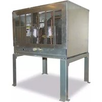
SRC-14H - Machine à glace Hoshizaki - Notice d'utilisation et mode d'emploi gratuit
Retrouvez gratuitement la notice de l'appareil SRC-14H Hoshizaki au format PDF.


| Type de produit | Machine à glace professionnelle |
| Marque | Hoshizaki |
| Modèle | SRC-14H |
| Production de glace | 14 kg / 24 h |
| Type de glace | Glaçons en croissant |
| Capacité du réservoir | 9 kg |
| Dimensions (L x P x H) | 560 x 600 x 800 mm |
| Poids net | 42 kg |
| Alimentation électrique | 230 V / 50 Hz / 1 phase |
| Consommation électrique | 300 W |
| Réfrigérant | R134a |
| Refroidissement | Air |
| Matériaux extérieurs | Acier inoxydable |
| Fonctions principales | Production automatique, arrêt automatique bac plein, cycle de nettoyage |
| Entretien et nettoyage | Nettoyage régulier du filtre à air et du condenseur, détartrage périodique |
| Sécurité | Protection contre la surchauffe, disjoncteur interne, verrouillage de sécurité |
| Réparabilité | Pièces détachées disponibles via réseau agréé Hoshizaki |
| Informations générales | Utilisation en intérieur, température ambiante 5-40°C |
FOIRE AUX QUESTIONS - SRC-14H Hoshizaki
Questions des utilisateurs sur SRC-14H Hoshizaki
0 question sur cet appareil. Repondez a celles que vous connaissez ou posez la votre.
Poser une nouvelle question sur cet appareil
Téléchargez la notice de votre Machine à glace au format PDF gratuitement ! Retrouvez votre notice SRC-14H - Hoshizaki et reprennez votre appareil électronique en main. Sur cette page sont publiés tous les documents nécessaires à l'utilisation de votre appareil SRC-14H de la marque Hoshizaki.
MODE D'EMPLOI SRC-14H Hoshizaki
Hoshizaki America, Inc.
Condensing Unit
Model SRC-14H

"A Superior Degree of Reliability"
www.hoshizaki.com
PARTS LIST

Number: 71334
Issued: 7-18-2011
Revised: 3-7-2016
CONTENTS
Auxiliary Codes....3
Note About Ordering Parts 3
A. Main Assembly & Refrigeration Circuit 4
B. Control Box Assembly....6
C. Accessories & Labels 7
Auxiliary Codes
SRC-14H
A-0 June 2011
B-0 January 2012
B-1 February 2012
C-0 January 2013
D-0 January 2014
E-0 February 2015
F-0 January 2016
Auxiliary Code Breakdown
The auxiliary code is the first two characters in the serial number. The first character indicates the year. Years progress or regress in alphabetical order. The series runs from "A" through "V" and the letters "I" and "O" are skipped. The second character indicates significant part changes within a year. Base is "0" and this number advances for each change. In cases where there is a letter in parentheses, this designates the month. This is the last character in the serial number. The series runs from "(A)" through "(M)" and the letter "(I)" is skipped. This designation is only included when identifying a parts change within an auxiliary code.
Note About Ordering Parts
Most assemblies cannot be ordered as complete units; parts in the assemblies generally must be ordered separately.
A. Main Assembly & Refrigeration Circuit
SRC-14H
A-0 to F-0

| Title: A. Main Assembly & Refrigeration Circuit Model: SRC-14H | |||||||||||
| Index No. | Description | Material or Model Number | Part Number | Required Number | |||||||
| A-0 to B-0 | B-1 to B-1 (K) | B-1 (L) to F-0 | |||||||||
| Condensing Unit | |||||||||||
| 1 Top Panel 3A5858-01 1 1 1 | |||||||||||
| 2 Side Panel 3A5855-01 2 2 2 | |||||||||||
| 3 Louver Panel 213968-01 1 1 1 | |||||||||||
| 4 Control Box Cover 3A3182-01 1 1 1 | |||||||||||
| 5 Fan Motor 4A3201-01 2 2 2 | |||||||||||
| 5a | Split Lock Washer | 7L22I0832 | 8 | 8 | - | ||||||
| 5b | Self Locking Nut | 7N21I0832 | 8 8 | 8 | |||||||
| 6 Fan Blade | 4A | 1493-01 2 2 2 | |||||||||
| Refrigeration Circuit | |||||||||||
| 7 Compressor(B-1 and later utilize external crankcase heater-item 8) | 4A4134-02 | 1 | - | ||||||||
| 4A4134-03 | 1 1 | ||||||||||
| 8 Crankcase Heater | 4A | 5397-02 | 1 | 1 | |||||||
| 9 Condenser | 10 | 4777-02 | 1 1 | ||||||||
| 10 | Receiver | 438209-01 | 1 | 1 | 1 | ||||||
| 11 | High-Pressure Switch | 463180-05 | 1 | 1 | 1 | ||||||
| 12 | Headmaster (Condensing Pressure Regulator) | 4A0229-01 1 | 1 | ||||||||
| 13 | Liquid Line Coupling | 426554-01 | 1 | 1 | 1 | ||||||
| 14 | Suction Line Coupling | 448569-01 | 1 | 1 | 1 | ||||||
B. Control Box Assembly
SRC-14H
A-0 to F-0

| Title: B. Control Box Assembly Model: SRC-14H | |||||||||||
| IndexNo. Description | Material orModel Number | Part Number | Required Number | ||||||||
| A-0toF-0 | |||||||||||
| 1 Fan Motor Capacitor 10MFD, | 250VAC | 443192-01 2 | |||||||||
| 2 Magnetic Contactor 4A0794-01 1 | |||||||||||
| 3 Start Capacitor 145-174MFD, | 220VAC | 3A0076-11 1 | |||||||||
| 4 Run Capacitor 30MFD, | 370VAC | 3A2005-03 1 | |||||||||
| 5 Start Relay 4A1107-13 1 | |||||||||||
| 6 Control Low-Pressure Switch | 4A5353G01 | ||||||||||
| 7 Safety Low-Pressure Switch | 4A3497-01 1 | ||||||||||
C. Accessories & Labels
SRC-14H
A-0 to F-0

| Title: C. Accessories & Labels Model: SRC-14H | |||||||||||
| IndexNo. Description | Material orModel Number | Part Number | Required Number | ||||||||
| A-0toF-0 | |||||||||||
| 1 Leg 2A3166G01 2 | |||||||||||
| 1a Hex Head Bolt w/ Washer 8×16, S$ 7B0230816 8 | |||||||||||
| 1b Hex Nut M8, SS 7N12-0800 8 | |||||||||||
Marque : Hoshizaki
Modèle : SRC-14H
Catégorie : Machine à glace