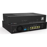
VM-4DKT - Recepteur Kramer - Notice d'utilisation et mode d'emploi gratuit
Retrouvez gratuitement la notice de l'appareil VM-4DKT Kramer au format PDF.


| Type de produit | Récepteur audio/vidéo |
| Marque | Kramer |
| Modèle | VM-4DKT |
| Alimentation | 12 V CC, 1 A (adaptateur secteur inclus) |
| Consommation électrique | 5 W max |
| Dimensions (L × P × H) | 12,0 × 7,5 × 2,5 cm |
| Poids | 0,2 kg |
| Entrées | 1 × HDMI, 1 × VGA (via adaptateur) |
| Sorties | 1 × HDMI, 1 × VGA (via adaptateur) |
| Résolution maximale | 1920 × 1200 (HDMI), 1080p (VGA) |
| Fonctions principales | Conversion de signaux, amplification, distribution |
| Entretien et nettoyage | Débrancher avant nettoyage ; utiliser un chiffon doux et sec |
| Sécurité | Utiliser dans un endroit sec et ventilé ; ne pas ouvrir |
| Pièces détachées et réparabilité | Adaptateur secteur disponible ; réparation par SAV agréé |
| Informations générales | Notice d'utilisation incluse ; garantie 2 ans |
FOIRE AUX QUESTIONS - VM-4DKT Kramer
Questions des utilisateurs sur VM-4DKT Kramer
0 question sur cet appareil. Repondez a celles que vous connaissez ou posez la votre.
Poser une nouvelle question sur cet appareil
Téléchargez la notice de votre Recepteur au format PDF gratuitement ! Retrouvez votre notice VM-4DKT - Kramer et reprennez votre appareil électronique en main. Sur cette page sont publiés tous les documents nécessaires à l'utilisation de votre appareil VM-4DKT de la marque Kramer.
MODE D'EMPLOI VM-4DKT Kramer

Scan for full manual
VM-4DKT Quick Start Guide
This guide HELPS you install and use your VM-4DKT for the first time.
Go to www.kramerav.com/downloads/VM-4DKT to download the latest user manual and check if firmware upgrades are available.
Step 1: Check what's in the box
VM-4DKT 1:4 4K HDMI/DGKAT Distribution Amplifier Transmitter
4 Rubber feet
1 Quick start guide
1 Power cord and adapter
IMPORTANT NOTICE!

We highly recommend using only Kramer UNIKAT cables with these products. If using 3^rd party shielded CAT-6A cables, both ends of the shield must be soldered to the connectors for the products to function properly. Do not use any jumpers, unshielded wall plates or mid-span cable connections. These extenders are not compatible with HDBaseT technologies. Prior to signal extension, ensure that the extension line cable is lying straight and not coiled.
Step 2: Get to know your VM-4DKT


flowchart
graph TD
    A["4 5"] --> B["LOG"]
    B --> C["1 HDMI IN"]
    B --> D["2 LOG"]
    E["6"] --> F["DGKAT2 OUTPUTS"]
    F --> G["1 2 3 4"]
    H["7"] --> I["SERVICE"]
    I --> J["2 3 4"]
    K["8"] --> L["SETUP"]
    L --> M["12V DC"]
    N["9"] --> O["I2V DC"]
| # | Feature | Function |
| 1 | STATUS LED | Red – Power up.Green – Power is on. |
| 2 | ACTIVE EDID LED | The LED color indicates the active EDID type. When flashing, the state is in the process of being activated.Yellow – Default EDID.Blue – Output-acquired EDID.Green – Custom EDID. |
| 3 | INPUT LED | On – Input signal detected.Flashing – Source connected, but no signal detected. |
| 4 | HDMI IN Connector | Connect to an HDMI source. |
| 5 | LOOP Connector | Connect to a local HDMI display. |
| 6 | DGKAT2 OUTPUTS Connectors (x4) | Connect to a DGKat-2.0 receiver (for example, PT-872xr) using twisted pair cable. |
| 7 | SERVICE 3-pin terminal block | Connect to a serial controller. |
| 8 | SETUP DIP-switches | Sets the device behavior (seeStep 6: Operate VM-4DKT). |
| 9 | Fan Vent | For heat ventilation. |
| 10 | 12V DC Power Connector | Connect the 12V DC power adapter into the device and then connect it to the mains. |
Step 3: Mount VM-4DKT
Install VM-4DKT using one of the following methods:
- Attach the rubber feet and place the unit on a flat surface.

- Ensure that the environment (e.g., maximum ambient temperature & air flow) is compatible for the device.
- Avoid uneven mechanical loading.
- Appropriate consideration of equipment nameplate ratings should be used for avoiding overloading of the circuits.
- Reliable earthing of rack-mounted equipment should be maintained.
• Maximum mounting height for the device is 2 meters.
Step 4: Connect inputs and outputs
Always switch OFF the power on each device before connecting it to your VM-4DKT.

flowchart
graph TD
    A["HDMI"] --> B["4K PC/NUC"]
    C["HDMI"] --> D["4K Monitor"]
    E["DGKat 2.0"] --> F["PG"]
    G["DGKat 2.0"] --> H["PG"]
    I["DGKat 2.0"] --> J["PG"]
    K["DGKat 2.0"] --> L["PG"]
    M["DGKat 2.0"] --> N["PG"]
    O["RS-232"] --> P["RC-206 Control Keypad"]
    B --> Q["4K Display"]
    D --> R["4K Monitor"]
    F --> S["4K Display"]
    H --> T["4K Display"]
    J --> U["4K Display"]
    L --> V["4K Display"]
    N --> W["4K Display"]
    P --> X["4K Display"]
    Y["DGKat2 OUTPUTS"] --> Z["1 2 3 4"]
    AA["SERVICE"] --> AB["G Rx Tx"]
    AC["SETUP"] --> AD["12V DC"]
Wiring the RJ-45 Connectors
This section defines the DGKAT pinout, using a straight pin-to-pin cable with RJ-45 connectors.

The ground shielding must be connected/soldered to the connector shield.

To achieve specified extension distances, use the recommended Kramer cables available at www.kramerav.com/product/VM-4DKT.
Using third-party cables may cause damage!

Step 5: Connect power
Connect the power adapter to the VM-4DKT and then plug it into the mains electricity.

Safety Instructions (See www.kramerav.com for updated safety information) Caution:
- For products with relay terminals and GPI\O ports, please refer to the permitted rating for an external connection, located next to the terminal or in the User Manual. - There are no operator serviceable parts inside the unit.
Warning:
- Use only the power cord that is supplied with the unit. - Disconnect the power and unplug the unit from the wall before installing.
Step 6: Operate VM-4DKT
Set the VM-4DKT DIP-switches:
A DIP-switch that is down is on, up is off. Changes to the DIP-switches take effect immediately.
| # | Function | Status | |
| 1 | Active EDID source | ON (down) – Default EDID (default) | OFF (up) – 1st OUT EDID |
| 2 | EDID auto-acquire | OFF (up) – Auto-acquire enabled (default) | ON (down) – Auto-acquire disabled |
| 3 | Input HDCP appearance | OFF (up) – Active (default) | ON (down) – Inactive |
| 4 | Compression setup | OFF (up) – Standard (default) | ON (down) – High |
| 5 | RS-232 operation mode | OFF (up) – Normal operation mode (default) | ON (down) – Firmware upgrade mode. |
Control the devices:
Operate remotely, by RS-232 serial commands transmitted by PC, or other serial controller.
| RS-232 Control / Protocol 3000 | |||
| Baud Rate: | 115,200 | Parity: | None |
| Data Bits: | 8 | Command Format: | ASCII |
| Stop Bits: | 1 | ||
| Example (get device model name): #model? | |||
| Factory Default Parameters | |||
| P3K command: | #factory | ||
Marque : Kramer
Modèle : VM-4DKT
Catégorie : Recepteur