
CWL-2-325 - Pompe à chaleur WOLF - Notice d'utilisation et mode d'emploi gratuit
Retrouvez gratuitement la notice de l'appareil CWL-2-325 WOLF au format PDF.


| Type de produit | Pompe à chaleur air-eau |
| Marque | Wolf |
| Modèle | CWL-2-325 |
| Dimensions (L × H × P) | 1100 × 800 × 700 mm |
| Poids | 65 kg |
| Alimentation électrique | 400 V triphasé, 50 Hz |
| Puissance thermique nominale | 11 kW |
| Plage de fonctionnement | -15°C à +35°C |
| Fluide frigorigène | R32 |
| Niveau sonore | 55 dB(A) à 1 m |
| Fonctions principales | Chauffage, refroidissement, production d'eau chaude sanitaire |
| Entretien et nettoyage | Nettoyage des filtres tous les 3 mois, vérification annuelle par un professionnel |
| Sécurité | Protection antigel, soupape de sécurité, arrêt d'urgence |
| Pièces détachées et réparabilité | Compresseur, ventilateur, échangeur thermique, filtre |
| Garantie | 2 ans pièces et main-d'œuvre |
| Indice de réparabilité | 7,5 / 10 |
FOIRE AUX QUESTIONS - CWL-2-325 WOLF
Questions des utilisateurs sur CWL-2-325 WOLF
0 question sur cet appareil. Repondez a celles que vous connaissez ou posez la votre.
Poser une nouvelle question sur cet appareil
Téléchargez la notice de votre Pompe à chaleur au format PDF gratuitement ! Retrouvez votre notice CWL-2-325 - WOLF et reprennez votre appareil électronique en main. Sur cette page sont publiés tous les documents nécessaires à l'utilisation de votre appareil CWL-2-325 de la marque WOLF.
MODE D'EMPLOI CWL-2-325 WOLF
Installation Instructions
HEAT-RECOVERY-UNIT

natural_image
Exterior view of a white industrial machine with control panel and display (no visible text or symbols)CWL - 300/400 Excellent
Standards and regulations .... 3 Explanation markers .... 4
1 Delivery....6
1.1 Scope of delivery....6
2 Application....7
3 Version....8
3.1 Technical information CWL-300 Excellent....8
3.2 Fan graph CWL-300 Excellent....8
3.3 Technical information CWL-400 Excellent....9
3.4 Fan graph CWL-400 Excellent....9
3.5 Connections and dimensions....1
3.5.1 CWL-300/400 Excellent Right-hand version...1
3.5.2 CWL-300/400 Excellent Left-hand version....1
3.6 Exploded view appliance....1
4 Operation....13 4.1 Description....13 4.2 Bypass conditions....13 4.3 Frost protection....13 4.4 Version....13
5 Installation.... 14 5.1 Installation general .... 14 5.2 Placing the appliance .... 14 5.3 Connecting the condensate discharge .... 14 5.4 Connecting ducts.... 14 5.5 Electric connections.... 16 5.5.1 Connecting the power plug.... 16 5.5.2 Connecting the multiple switch.... 16 5.5.3 Connecting the eBus connector .... 16
6 Display.... 17 6.1 General explanation control panel.... 17 6.2 Operation mode.... 18 6.2.1 Status System fan.... 18 6.2.2 Display air flow rate.... 18 6.2.3 Message text for operation mode.... 19 6.3 Settings menu.... 20 6.4 Read out menu.... 21 6.5 Service menu.... 22
7 Putting into operation....23 7.1 Switching the appliance on and off....23 7.2 Setting the airflow rate....24 7.3 Other settings installer....24 7.4 Factory setting....24
8 Fault.... 25 8.1 Trouble shooting.... 25 8.2 Display codes.... 25
9 Maintenance.... 27 9.1 Filter cleaning.... 27 9.2 Maintenance.... 28
10 Elektric diagrams.... 30 10.1 Basic diagram.... 30 10.2 Wiring diagram.... 31
11 Elektric connections accessoires.... 32 11.1 Connectors.... 32 11.2 Connection examples multiple switch.... 33 11.2.1 Multiple switch with filter indication.... 33 11.2.2 Wireless remote control (without filter indication).... 33 11.2.3 Additional multiple switch with filter indication.... 33 11.2.4 Additional multiple switch with wireless remote control.... 33 11.3 Couple CWL-300/400 Excellent through eBus contact; all appliances equal air flow rate.... 34 11.4 Wiring diagram postheater connection or extra preheater.... 35 11.5 Connection example geo heat exchanger.... 36 11.6 Connecting external switch contact.... 37 11.7 Connection to 0 - 10V.... 38 11.8 Connection RH (humidity) - sensor.... 39 12 Service.... 40 12.1 Exploded view.... 40 12.2 Notes.... 41 13 Setting values.... 42
Declaration of conformity.... 46
Standards
For the Comfort domestic ventilation units of CWL Excellent series, check the following standards and requirements:
- EC Directive 2004/108/EC on the approximation of the laws of Member States relating to electromagnetic compatibility (EMC Directive)
- EC Directive 2006/95/EC relating to electrical equipment designed for use within certain voltage limits (Low Voltage Directive)
- EC Directive 2011/65/EU on the restriction of use of certain hazardous substances in electrical and electronic equipment (RoHS Directive)
- DIN EN 12100/1+2 Safety of machinery; general design principlese
- DIN EN ISO 13857 Safety of machinery safety distances
- DIN EN 349 Safety of machinery; minimum gaps
- VDE 0700/500 Safety of electrical appliances for household and similar purposes
- EN 60335/1 Safety of electrical appliances; general requirements EN 60730
- EN 6100 Electromagnetic compatibility
For the planning and execution of a controlled ventilation following standards and regulations must be observed:
EN 12792 Ventilation Technology, terminology and symbols
DIN EN 13779 Ventilation Technology; Health Technical Requirements
DIN 1946-6 Ventilation Technology, ventilation of apartments
DIN 1946-10 Ventilation Technology, ventilation of apartments
DIN 4719 Residential ventilation - Requirements, testing and marking of performance ventilation devices
DIN 18017-3 Ventilation of bathrooms and toilet rooms without outside windows with fans
DIN EN 832 Thermal performance of buildings; calculation of heating energy needs - residential building
VDI 2071 Heat recovery ventilation systems
VDI 2081 Noise generation and noise reduction in ventilation systems
VDI 2087 Air duct systems - bases
VDI 3801 Operation of ventilation systems
VDI 6022 Hygienic standards for ventilation systems
EnEV Energy Saving Regulation
These instructions must be kept available as a part of the unit supplied!
General information
These service instructions are only applicable to CWL 300/400 Excellent
Authorised personnel should read these instructions before any commissioning or maintenance work.
Observe the instructions given in this document. Installation, commissioning and maintenance work must only be carried out by trained personnel.
These instructions should be considered an integral part of the unit supplied, and should always be easily accessible.
Failure to observe these installation and service instructions voids any Wolf GmbH warranty.
Reference symbols
The following symbols are used in this instruction manual. This important information concerns personal as well as operational safety."

“Safety instructions” are instructions which you must follow exactly, to prevent risks or injuries to individuals, and damage to the unit.

Danger through 'live' electrical components! Please note: Turn off the ON/OFF switch before removing the casing. Never touch electrical components or contacts when the ON/OFF switch is in the ON position. This would lead to a risk of electrocution that may lead to injury or death. The main supply terminals are 'live' even when the ON/OFF switch is in the OFF position.
Please note
“Please note” designates technical instructions which you must observe to prevent the unit malfunctioning or being damaged.
Safety instructions
Only qualified and trained personnel may be appointed for the installation, commissioning, servicing and operation of the unit.

Electrical installation and repair work on electrical components may only be carried out by qualified electricians.
Only qualified electricians are permitted to work on the electrical systemVDE regulations [or local regulations] and those of your local power supply utility are applicable to electrical installation work.
The CWL CWL Excellent ventilation unit must only be operated within the power range that is specified in the technical documentation supplied by the wolf.
Safety and monitoring equipment must not be removed, bypassed or put out of operation in other ways.
Only operate the unit when it is in perfect technical condition. Any faults or damage which impact or might impact upon the safety or correct function of the unit must be remedied immediately by qualified personne In this case shut off the appliance immediately to prevent further use.
Intended use
The CWL CWL Excellent ventilation unit is a central ventilation system with integrated heat recovery for ventilation and venting of one or more rooms in apartments and houses.
With this device, the used air is extracted from the kitchen, bathroom and toilet, filtered and removed from the heat transported through the heat exchanger into the open.
At the same time fresh outside air is sucked in, cleaned by an air filter, heated by the heat exchanger and supplied to areas such as living room, bedroom and nursery.
| Determining the proper use | The intended use of the device includes the exclusive use for ventilation purposes.Only air may be displacedThe unit must only be permitted to handle air. This air must not contain any harmful, combustible, explosive, aggressive, corrosive or otherwise dangerous substances, as these would be distributed throughout the duct system or building, where they could cause a risk to health of, or even kill the occupants, animals or plants living there.Exhaust ventilation systems such as Hoods, laboratory extractors, vacuum systems, etc. must not be connected to the device.These exhaust systems have to be operated separately. |
| Installation site | The device may only be installed in a frost-protected area.The device must be mounted horizontally.The site is so determined that sufficient condensate drain can be guaranteed.The device must not be in the immediate vicinity of flammable liquids and gases, or in places with high humidity (eg swimming pools) or chemical attack aggressively modified installed.For maintenance, a space of 70 cm in front of the appliance is required. |
| Operating instructions | Let instruct you on the operation by which the practitioner is responsible for the installation of the device and its control.Do not make any changes to the device.Change at longer periods of standstill for hygiene reasons, the filter before being used again.In homes with ventilation systems subject to open flue combustion equipment of DIN 1946-6. |
| Maintenance | Check the unit periodically for function, damage and dirt.During maintenance, disconnect the appliance from the mains and secure it against accidental reconnection.Only replace faulty components and equipment with original WOLF spare parts.Any modification of the appliancee and when NOT using original Wolf spare parts, the warranty claim against the company Wolf goes out. |
| Disposal | For the disposal of faulty system components or the system and recycling at the end of the product service life, observe the following information: Dispose of all equipment in accordance with applicable regulations, i.e. separate material groups correctly. The aim should be the maximum possible recycling of basic materials with the least environmental impact. Never throw electrical or electronic scrap into the household waste, but recycle it appropriately. Generally, dispose of materials in the most environmentally responsible manner according to environmental, recycling and disposal standards. |
1.1 Scope of delivery
Before starting installation of the heat recovery unit, check that it has been supplied complete and undamaged.
The scope of delivery of the heat recovery unit Typ CWL-300/400 Excellent includes the following components:
① Heat recovery appliance type CWL-300/400 Excellent
② Wall mounting bracket kit containing:
- 2 x suspension strips
- 3 x protective caps
- 1 x rubber strip
- 2 x rubber rings
- 1 x mounting instructions
③ PVC condensate discharge connection containing:
- 1 x synthetic screw gland 1.5"
- 1 x sealing ring
• 1 x PVC glued coupling 32 mm
④ Documentation set consisting:
- 1 x installation instructions
• 1 x occupants instructions

natural_image
Technical line drawing of a four-tiered industrial machine with labeled components (no text or symbols beyond label)

natural_image
Technical diagram showing two parallel metal strips with circular holes, labeled with number 2 (no text or symbols on the strips themselves)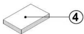
The CWL-300/400 Excellent is a ventilation unit with heat recovery with an efficiency of 95%, a maximum ventilation capacity of 300 or 400 m ^3 /h and low-energy fans. Features CWL-300/400 Excellent:
- steplessly adjustable air flow rates through a control panel;
- filter indication on the appliance and the possibility for filter indication on the multiple switch;
- a completely new intelligent frost protection system ensures that also at low outdoor temperatures the appliance's performance remains optimal and that, if necessary, it activates the standard preheater.
- low sound level
• comes as standard with automatic bypass valve - constant flow control
- low energy consumption
- high efficiency
The CWL-300/400 Excellent is available in the left-handed or right-handed version. A left-handed version has the filters on the left behind the filter door; a right-handed version has the filters on the right behind the filtered door. The position of the air ducts differs for these two versions! For the correct position of the connection ducts and dimensions see § 3.5.1 or § 3.5.2, respectively.
which When ordering an appliance always state the correct type; subsequent conversion to a different version is not possible.
The CWL-300/400 Excellent comes ready to plug in with a 230 V mains plug and a connection for a low-voltage multiple switch on the outside of the appliance.
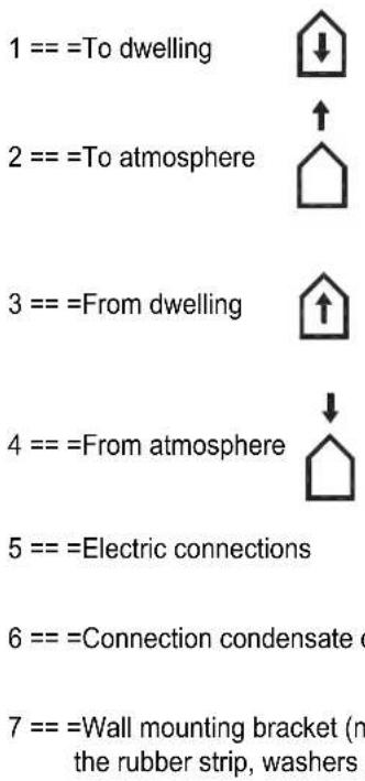
Note: When replacing a CWL-300/400 by a CWL-300/400 Excellent, do realise that the positions of the ducts "From dwelling" and "From atmosphere" are different! (only for type 4/0 & 3/1) Carefully check the position of these ducts on the basis of the connection drawings §3.5.1 and §3.5.2.
Note: With enterprise of fire places and ventilation systems and/or devices.
Apply the provisions of the relevant district chimney sweep. This is to be drawn from the planning period to rate.
3.1 Technical information CWL- 300 Excellent
| CWL - 300 Excellent | ||||
| Supply voltage [V/Hz] 230/50 | ||||
| Protection degree IP30 | ||||
| Dimensions (w x h x d) [mm] 675 x 765 x 564 | ||||
| Duct diameter [mm] ∅160 | ||||
| External diameter condensate discharge [mm] ∅32 | ||||
| Weight [kg] 38 | ||||
| Filter class G4 (F7 optional for supply) | ||||
| Fan setting (factory setting) | 1 | 2 | 3 | |
| Ventilation capacity [m3/h] 50 100 150 225 | ||||
| Permissible resistance ducts system [Pa] | 3 - 7 | 11 - 28 | 26 - 66 | 56 - 142 |
| Rated power (excl. preheater)[W] | 9,0 - 9,2 | 13,7 - 15,2 | 22,0 - 29,2 | 46,8 - 66,2 |
| Rated current (excl. preheater)[A] | 0,104 - 0,107 | 0,150 - 0,161 | 0,214 - 0,274 | 0,403 - 0,578 |
| Max. rated current (with preheater switched on) [A] | 6 | |||
| Cos φ | 0,368 - 0,374 | 0,391 - 0,416 | 0,447 - 0,463 | 0,506 |
| Sound power CWL-300 Excellent | |||||||||
| Ventilation capacity [m3/h] | 90 | 150 | 210 | 300 | |||||
| Sound power level Lw (A)) | Static pressure [Pa] | 50 | 100 | 50 | 100 | 50 | 100 | 50 | 100 |
| Housing emission [dB(A)] | 30 | 33 | 38 | 38 | 44 | 46 | 50 | 52 | |
| Duct “from dwelling” [dB(A)] | 33 | 34 | 39 | 42 | 45 | 46 | 54 | 54 | |
| Duct “to dwelling” [dB(A)] | 44 | 47 | 52 | 55 | 60 | 60 | 67 | 67 | |
In practice, the value may deviate 1 dB(A) as a result of measuring tolerances
3.2 Fan graph CWL-300 Excellent

line
| Flow rate [m³/h] | Resistance ducts system [Pa] | | ---------------- | ---------------------------- | | 50 | 5 | | 100 | 8 | | 150 | 15 | | 200 | 26 | | 225 | 33 | | 250 | 44 | | 300 | 59 | | 300 | 52 | | 300 | 46 |3.3 Technical information CWL-400 Excellent
| CWL - 400 Excellent | ||||
| Supply voltage [V/Hz] 230/50 | ||||
| Protection degree IP30 | ||||
| Dimensions (w x h x d) [mm] 675 x 765 x 564 | ||||
| Duct diameter [mm] ∅180 | ||||
| External diameter condensate discharge [mm] ∅32 | ||||
| Weight [kg] 38 | ||||
| Filter class G4 (F7 optional for supply) | ||||
| Fan setting (factory setting) | 1 | 2 | 3 | |
| Ventilation capacity [m3/h 50 100 200 300 | ||||
| Permissible resistance ducts system [Pa] | 3 - 6 | 6 - 20 | 25 - 49 | 56 - 178 |
| Rated power (excl. preheater)[W] | 8,6 | 9,5 - 15 | 29 - 40 | 72 - 98 |
| Rated current (excl. preheater)[A] | 0,10 | 0,12 - 0,14 | 0,24 - 0,31 | 0,51 - 0,7 |
| Max. rated current (with preheater switched on) [A] | 6 | |||
| Cos φ | 0,38 | 0,45 - 0,40 | 0,56 - 0,58 | 0,60 - 0,61 |
| Sound power CWL-400 Excellent | ||||||||||||
| Ventilation capacity [m3/h] | 100 | 200 | 225 | 300 | 400 | |||||||
| Sound power level Lw (A) | Static pressure [Pa] | 9 | 40 | 38 | 80 | 47 | 100 | 84 | 175 | 240 | 150 | 225 |
| Housing emission [dB(A)] | 28,5 | 31,5 | 39,5 | 40,5 | 42,5 | 46,5 | 50,0 | 52,0 | 53,0 | 53,5 | 56,0 | |
| Duct “from dwelling” [dB(A)] | 30,5 | 33,5 | 45,5 | 47,0 | 47,5 | 49,0 | 55,5 | 56,0 | 57,0 | 58,0 | 59,0 | |
| Duct “to dwelling” [dB(A)] | 41,5 | 46,5 | 560 | 58,0 | 59,5 | 61,5 | 65,0 | 67,5 | 68,5 | 69,5 | 79,5 | |
In practice, the value may deviate 1 dB(A) as a result of measuring tolerances
3.4 Fan graph CWL-400 Excellent

line
| Flow rate [m³/h] | Resistance ducts system [Pa] | | ---------------- | ---------------------------- | | 50 | 5 | | 100 | 7 | | 150 | 10 | | 200 | 15 | | 225 | 19 | | 250 | 23 | | 300 | 36 | | 350 | 51 | | 375 | 58 | | 400 | 71 | | 425 | 83 |Note: The value stated in the circle is the capacity per fan (in Watt)
3.5 Connections and dimensions CWL-300/400 Excellent
3.5.1 CWL-300/400 Excellent, right-handed version

CWL-300/400 Excellent Right-handed 2/2

CWL-300/400 Excellent Right-handed 4/0

CWL-400 Excellent Right-handed (no CWL-300 Exc.)
3.5.2 CWL-300/400 Excellent, left-handed version
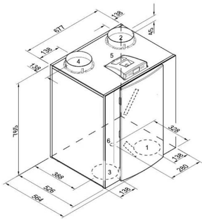
CWL-300/400 Excellent left-handed 2/2
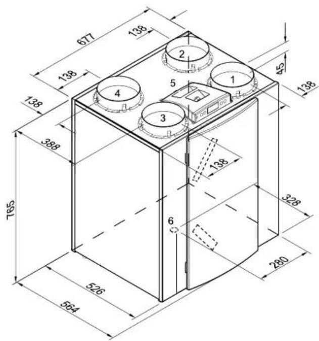
CWL-300/400 Excellent left-handed 4/0

CWL-400 Excellent left-handed 3/1 (no CWL-300 Exc.)

Mounting wall suspension kit Extra assembly instructions included with suspension kit.
3.6 Exploded view appliance
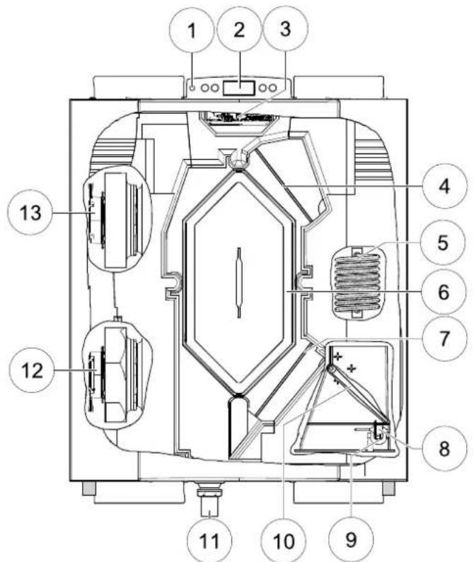
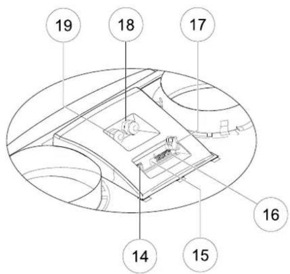
Rear view display cover
| 1 | Service connector Computer connection for service purposes. | |
| 2 | Display and 4 control buttons Interface between user and control electronics. | |
| 3 | Control board Contains the control electronics for the basic functions. | |
| 4 | Extract air filter Filters air flow from dwelling | |
| 5 | Preheater | Heats up the outdoor air when there is a risk of freezing for the heat exchanger |
| 6 | Heat exchanger Ensures heat transfer between input and output air | |
| 7 | Supply air filter Filters outdoor are supplied to the dwelling | |
| 8 | Outdoor temperature sensor Measures outside air temperature. | |
| 9 | Indoor temperature sensor Measures the dwelling air temperature | |
| 10 | Bypass valve | Sends the air through or around the heat exchanger (For the 3/1 and 4/0 this valve is in the upper part of the appliance) |
| 11 | Condensate discharge | Connection condensate discharge (Kit comes separately with the appliance) |
| 12 | Extract fan Discharges air from the dwelling to the atmosphere. | |
| 13 | Supply fan Feeds fresh air into the dwelling. | |
| 14 | Modular connector multiple switch X2 | Connections for cable to multiple switch, if desired with filter indicator. |
| 15 | Connector eBus X1 | Connection for eBus control |
| 16 | Connector X15 Contains the various control inputs and outputs | |
| 17 | Connector X14 | Connection postheater (accessible after taking off the display cover) |
| 18 | Mains cable 230 V | Gland power cable 230 volt |
| 19 | Connection to the postheater or to the additional preheater | Gland 230 V cable to postheater or to the additional preheater |
4.1 Description
The appliance comes plug and play and operates fully matically. The extracted indoor air heats up the fresh, outdoor air. That saves energy and fresh air is sent to the required rooms.
auto the control system has three ventilation modes. The air flow clean rate can be adjusted per ventilation mode. The constant volume control system ensures that the air flow rate of the supply and extract fans is realised independent of the duct pressure.
4.2 Bypass conditions
The standard bypass valve makes it possible to supply fresh outside air that is not heated by the heat exchanger. Particularly during summer nights it is desirable to supply cooler outside air. Then the hot air in the dwelling is replaced by cooler outside air in so far as possible.
The bypass valve opens and closes automatically when a number of conditions are satisfied (refer to the table below for bypass conditions).
The operation of the bypass valve can be adjusted in step number 5, 6 and step number 7 in the settings menu (see chapter 13).
| Bypass valve conditions | |
| Bypass valve open | - The outdoor temperature is higher than 10°C and- the outdoor temperature is lower than the indoor temperature in the dwelling and- the temperature in the dwelling is higher than the temperature set at step no. 5 in the settings menu (set standard at 22°C). |
| Bypass valve closed | - The outdoor temperature is lower than 10°C or- the outdoor temperature is higher than de indoor temperature in the dwelling or- the temperature outside the dwelling is lower than the temperature set at step no. 5 in the settings menu minus the set temperature on the hysteresis (step no 6), this temperature is standard set at 20 °C (22.0 °C minus 2.0 °C). |
4.3 Frost protection
The unit has an intelligent frost protection.
Function description:
After activation of the frost protection (outdoor temperature <-1.5^ ), the preheater is continuously turned on as soon as the heat exchanger starts to freeze.
The icing is detected by pressure sensors.
The supply and exhaust fan continues to run with equal amounts of air.
Only when the power of the pre-heating is not sufficient for deicing, is also lowered over the control of the supply fan stepless until shutdown.
4.4 Version
The CWL-300/400 Excellent is equipped with 2 connectors (X14 & X15) with connection options for various applications.
The 9-pole connector X15 is accessible at the rear of the CWL-300/400 Excellent display cover without having to open the appliance.
The 2-pole connector X14 is accessible after taking off the display cover. The display cover has a second gland. That makes it possible to feed a 230 volt cable, which may be connected to connector X14, from outside the appliance.
See § 11.1 for more information on the connection possibilities of connectors X14 and X15.

natural_image
Technical diagram of a device with labeled component X15, showing internal components and wiring (no readable text or symbols beyond label)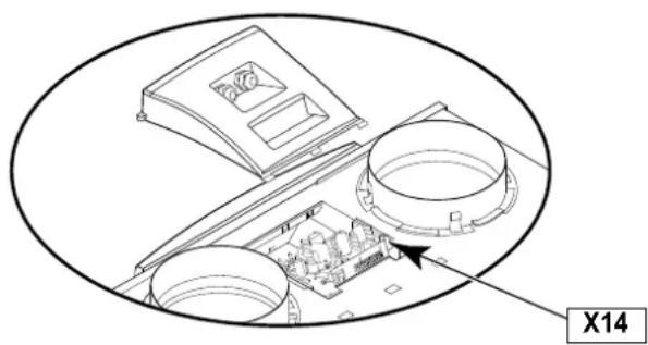
natural_image
Technical diagram of an electronic device with labeled components and a marked section X14 (no readable text or symbols)5.1 Installation general
Installing the appliance
- Placing the appliance (§5.2)
- Connecting the condensate discharge (§5.3)
- Connecting the ducts (§5.4)
- Electric connection
Connecting the mains power ( § 5.5.1 ), multiple switch ( § 5.5.2 ) and, if necessary, the Ebus coupler ( § 5.5.3 ).
Installation must take place under:
• Quality requirements ventilation systems dwellings.
- The safety regulations for low-voltage installations.
- The regulations for ventilation of dwellings and residential buildings.
- Any additional regulations of the local utilities.
• The installation instructions.
5.2 Placing the appliance
The CWL-300/400 Excellent can directly be mounted to the wall using the suspension brackets supplied for that purpose. For a vibration-free result the appliance must be mounted to a solid wall with a minimum mass of 200 kg/m ^2 . A gypsum block or metal stud wall does not suffice! Additional measures such as double panelling or extra studs are required in that case. On request, a mounting support for floor mounting is available (only 4/0 version). In addition, the following aspects must be taken into account.
• The appliance must be placed level.
- The installation room must be such that a good condensate discharge with air trap and pitch for condensate can be made.
- The installation room must be frost-free.
- Make sure there is a free space of at least 70 cm at the front of the appliance and a free headroom of 1.8 m fo cleaning the filters and carrying out maintenance.
- Make sure there is a free space of at least 20 cm above the display cover so it can always be removed.
5.3 Connecting the condensate discharge
The condensate discharge line for the CWL-300/400 Excellent is fed through the lower panel. The condensate must be discharged through a drainpipe.
The condensate discharge comes separately with the appliance and the installer must screw it into the underside of the appliance. This condensate discharge connection has an external connecting diameter of 32 mm.
The condensate discharge line can be glued to it, if necessary using a square bend. The installer can glue the condensate discharge in the desired position in the lower part of the appliance. The drain must discharge under the water level in the U-trap
Before connecting the condensate discharge to the appliance, pour water into the U-trap to create an air trap.

5.4 Connecting ducts
The air extract duct does not have to be fitted with a control valve. The appliance itself controls the air flow rates.
To prevent condensation on the outside of the outdoor air supply duct and the air extract duct from the CWL-300/400 cellent, these ducts must be provided with an external vapour barrier as far as the appliance. If synthetic (EPE) pipe is used here, additional insulation is not necessary.
For optimum fan noise damping, it is recommended to use acoustic ducts with a length of 1.5 m between the appliance and the ducts from and to the dwelling.
Pay attention to crosstalk and installation noise, also for incorporated ducts. Design the duct with separate branches to the valves to prevent crosstalk. If necessary, the supply ducts must be insulated, for instance when they are installed outside the insulated envelope.
A duct diameter of 180 mm is required for the CWL-400 Excellent, for the CWL-300 Excellent can suffice with a duct diameter of 160 mm.

1 = CWL-300/400 Excellent left-handed 2/2 (place level)
2 = Preferred ventilation air supply
3 = Ventilation air supply under the tiles
4a = Free suction bottom roof area
4b = Free suction top roof area
5 = Sewer vent
6 = Preferred location extract ventilation air; use insulated ventilation roof sleeve.
7 = Synthetic high efficiency heat recovery duct
8 = Condensate discharge
9 = Acoustic duct
10 = Ducts from and to dwelling
- Arrange the exterior air supply from the shadowed side of the dwelling, preferably from the wall or overhang. If the outdoor air is sucked in from under the tiles, it must be ensured that no condensation develops in the roof boarding and no water can run in. Ventilation air can be sucked in from under the tiles if air can access freely at the top and the bottom of the roof area and the sewage vent stack does not end under the tiles.
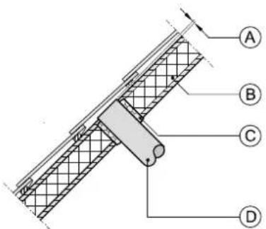
A = Spacing 10 mm above roof deck
B = Roof insulation
C = Seal with foam
D = Pipe for make-up air to be carefully insulated and provided with vapour barrier
- Feed the extract duct through the roof boarding in such a manner that no condensation develops in the roof boarding.
- Install the extract duct between the CWL-300/400 Excellent and the roof sleeve in such a manner that surface condensation is prevented.
• Always use an insulated ventilation roof sleeve. - The maximum permissible resistance in the duct system is 150 Pa at the maximum ventilation capacity. If the resistance of the duct system is higher, the maximum ventilation capacity will be lower.
- The location of the mechanical ventilation output and the sewer stack vent relative must be chosen to prevent nuisance
- Choose the location of the supply valves to prevent fouling and draught.
Install sufficient overflow openings, door gap 2 cm.
5.5 Electric connections
5.5.1 Connecting the power plug
The appliance can be connected to an easily accessible, earthed wall socket with the plug that is mounted to the pliance. The electric installation must comply with the requirements of your power company.
ap-
Make allowance for the 1000 W preheater.
Warning
The fans and control board carry a high voltage. Always take the voltage from the appliance by pulling the power plug when working on the appliance.
5.5.2 Connecting the multiple switch
The multiple switch (not supplied with the appliance) is connected to the modular connector type RJ12 (connector X2) that is placed at the rear of the appliance's display cover.
- Application of a 4-way switch with filter indication in all cases requires an RJ12 plug in combination with a 6-core modular cable.
Refer to diagrams §11.2.1 to §11.2.4 for connection examples multiple switch.
Other options include wireless remote control or a combination of multiple switches

5.5.3 Connecting eBus connector
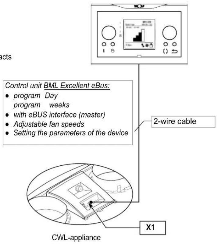
The CWL-300/400 Excellent works with the eBUS protocol. To connect a eBUS connection, there is the 2-pin connector X1 on the rear side of the display cover.
The eBus protocol can for instance be used for coupling (cascade control) appliances (see §11.3). Because of polarity sensitivity, always connect contacts X1-1 to X1-1 and contacts X1-2 to X1-2; the appliance will not work when these contacts are interchanged!
Control unit BML Excellent (eBus)
6.1 General explanation control panel
The LCD display shows what the operating situation of the appliance is. Four control keys can be used to call up and modify settings in the control unit program.
When the mains power to the CWL-300/400 Excellent is switched on, all display symbols will appear during 2 seconds; at the same time the blue backlight is switched on for 60 seconds..
When one of the control keys is operated, the display will light up during 30 seconds.
When no keys are operated or when no deviating situation has developed (such as a blocking fault) the display will show the operating mode (see § 6.2).
After operating the key 'Menu', the keys "+" or "-" can be used to select from three different menus, including:
- Settings menu (SET); see § 6.3
- Readout menu (READ), see § 6.4
• Service menu (SERV), see § 6.5
Press the R key to leave any menu and return to opera mode.
Briefly press the R key (shorter than 5 seconds) to switch on the display backlight without changing anything in the menu.

A = LCD
B = 4 control keys
C = service connector
| Key Function key | |
| Menu Activate the settings menu; to the next step in the submenu; confirm value change | |
| - | Scroll; modify value; Switching on or off the CWL-300/400 Excellent from operating mode (the press for 5 seconds) |
| + Scroll; modify value | |
| R One step back in menu; cancel value modification; filter reset (the press for 5 seconds), delete fault history | |
6.2 Operating mode
In operating mode the display may simultaneously show 4 different situations/values.
1 = Status fan situation, image coupled appliances (see § 6.2.1)
2 = Air flow rate (see § 6.2.2)
3 = Message text e.g. text filter situation, activation external switch contact etc. (see § 6.2.3)
4 = Fault symbol (see § 8.1 and § 8.2)

6.2.1 Status system fan
This part of the display shows a fan together with a number. When the supply and extract fans are running, the fan symbol is displayed. When the fans are stopped, the fan symbol is not visible. The number behind the fan symbol indicates the fan situation. Refer to the table below for an explanation of the numbers.

| Status fan situation on display | Description |
| The supply and extrad fans are running at 50 m^3/h or are inactive.This situation depends on setting parameter 1 (see Chapter 13) | |
| 1 | The supply and extract fans are running under mode 1 of the multiple switch.Air flow rate depends on setting parameter 2 (see chapter 13). |
| 2 | The supply and extract fans are running under mode 2 of the multiple switch.Air flow rate depends on setting parameter 3 (see chapter 13). |
| 3 | The supply and extract fans are running under mode 3 of the multiple switch.Air flow rate depends on setting parameter 4 (see chapter 13). |
| This CWL-300/400 Excellent is coupled with the aid of eBus.The supply and extract fans of the CWL-300/400 Excellent are running under switched mode of the ventilation mode “master” CWL-300/400 Excellent in addition, (only for cascade connection) the display shows the “slave” number of the relevant CWL-300/400 Excellent.Air flow rate depends on the set parameters “master” CWL-300/400 Excellent. |
6.2.2 Display air flow rate
This shows the set air flow rate of the supply of extract fan. When when the air flow rates of the supply and extract fans differ, for instance when using an external switch contact, in all cases the highest air flow rate is shown.
When the appliance is switched off through software, the text "OFF" appears here.

6.2.3 Message text for operating mode
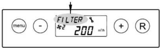
This part of the display may show a message text. The message text "Filter" always takes precedence over the other message texts.
The following message text may appear during operating mode.
| Message text on display | Description | |
| FILTER When the text “FILTER” appears on the display, the filter must be cleaned or replaced; for detailed information, see § 9.1 |  | |
| Slave 1, Slave 2 usw. | For coupled appliances the message text shelves which appliances “Slave 1” - “Slave 9”; for detailed information, see §11.3.The “Master” appliance displays the regular image regarding ventilation mode. | 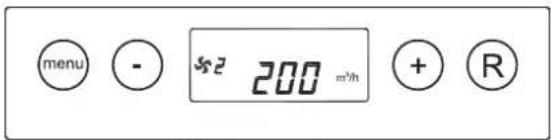 Master - appliance Master - appliance Slave - appliance Slave - appliance |
| EWT When the text “EWT” appears on the display, the geo heat exchanger is active.For extensive information, also see §11.5. |  | |
| CN1 oder CN2 When the text “CN1 or CN2” appears on the display, one of the external switch inputs is active, also see §11.6. | 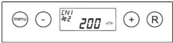 | |
| V1 oder V2 When the text “VN1 or VN2” appears on the display, one of the external 0 - 10 V inputs is active, also see §11.7. | 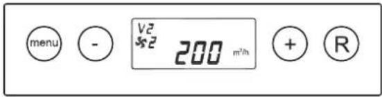 | |
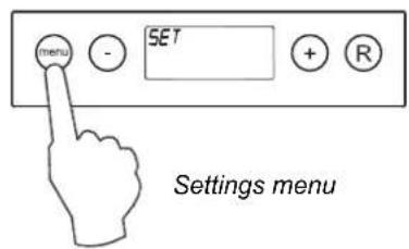
6.3 Settings menu
For optimum performance of the appliance, set values can be modified in the settings menu to adjust the appliance to installation situation; refer to chapter 13 for a list of the set values. A number of set values, such as the air flow rates, are laid down in the design data.
Warning:
Incorrect settings may seriously affect the proper performance of the appliance!
Modifying the set value in the settings menu:
- In operating mode, press the 'MENU' key.

- Press the 'Menu' key to activate the "settings menu".
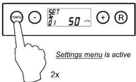
3 Select the set value to be modified with the '+' or '-' key.

Selection setting value to be modified.
4 Press the 'Menu' key to select the required set value.
the

5 Use keys '-' and '+' key to modify selected set value.

6 Store modified set value

Do not store modified set value
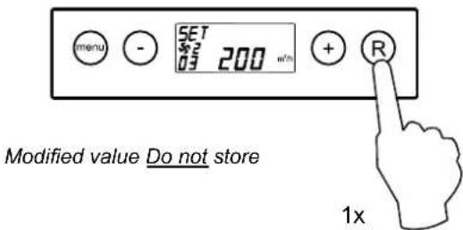
7 To modify other set values, repeat step 3 - 6. When you do not want to modify any more set values and return to operating situation, then press the 'R' key.

6.4 Readout menu
The =readout =menu =can =be =used =to =call =up =a =number =of 3. =Activate the readout menu.
current = sensor = values = to = obtain = more = information = on the = appliance's = performance. = Modifying = values = of = settings is not possible in the readout menu. The readout menu can be displayed as follows.
- =In operating mode, press the 'MENU' key. Now the display shows the settings menu.

Operating mode
- Use the '+' and the '-' key to go to the readout menu.

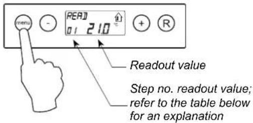
- =Use the '+' and the '-' key to scroll through the rear menu.

- =Press =the='R' =key =twice =to =go =back =to =operating =mode =If no key is operated during 5 minutes, the appliance automatically returns to operating mode.

| Step no. readout value | Description readout value Unit | |
| 01 Current temperature from dwelling=°C | ||
| 02 Current temperature outdoors sensor | °C | |
| 03 | Bypass status (ON = bypass valve open, OFF = bypass valve closed) | |
| 04 | Status frost protection (ON = frost protection active, OFF = frost protection not active) | |
| 05 Current channel pressure supply =Pa | ||
| 06 Current duct pressure extract=Pa | ||
| 07 Current air flow rate supply fan=m | ^3/h | |
| 08 Current air flow rate extract fan | m | ^3/h |
| 09 Actual relative humidity | % | |
6.5 Service menu
The service menu shows the most recent 10 fault messages.
In the event of a locking fault, the settings menu and the re-
adout menu are blocked and only the service menu can be opened; Pressing the 'menu' key directly opens the service menu.
The service menu can be displayed as follows.
- In operating mode, press the 'MENU'-key. The display now shows the settings menu.

- Use the '+' and the '-' key to go to the service menu.

- Activate the service menu.

- Use the '+' and the '-' key to scroll through the messages in the service menu.

- Display not any fault message.
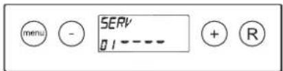
- Current fault message (spanner on display).
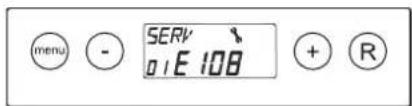
- Unsolved fault message (no spanner on display).

- Press the 'R' key twice to go back to operating mode. If no key is operated during 5 minutes, the appliance automatically returns to operating mode.

All fault messages can be deleted by pressing the "R" key in the service menu during 5 seconds; This is only possible when there is no active fault!
7.1 Switching the appliance on and off
There are two methods to switch the appliance on or off.
- Switching on and off by inserting or pulling the power plug.
- Switching on and off through software on the appliance display.
Switching on
• Switching on the mains power.
Connect the 230 V power plug to the electric system.

natural_image
Simple line drawing of a plug inserted into a socket (no text or symbols)All display symbols appear during 2 seconds.

2s
The software version appears during 2 seconds.

2s
Directly after that the CWL-300/400 Excellent will be running in the mode is set on the multiple switch. If no multiple switch is connected, the appliance will always run in mode 1.

• Switching on through software
When the CWL-300/400 Excellent switched off through software, the display will show the text "OFF".

The appliance can be switched on by pressing the key during 5 seconds.

Switching off:
• Switching off through software
Press the “-” key for 5 sec. to switch off the appliance through software. The text ‘OFF’ appears on the display.

- Switching off the mains power;
Pull the 230 V mains plug from the mains to take the voltage from the appliance.
Nothing is shown on the display now.


Warning
When working on the appliance, always take the voltage from the appliance by first switching it off through software and subsequently pulling the power plug.
7.2 Setting the air flow rate
The factory supplies the CWL-300/400 Excellent for the CWL-Excellent 300 flow rates set to 50, 100, 150 en 225m^-3/h and for the CWL-Excellent 400 set to 50, 100, 200 and 300m^-3/h respectively. The performance and the energy consumption of the CWL-300/400 Excellent depend on the pressure drop in the duct system as well as on the filter resistance.
If these conditions are not complied with, the air flow rate of the higher mode will automatically be adjusted.
See the settings menu, §6.3, for changing the flow rates.
Important:
Mode ∞: is 0 or 50/hm(not in combination with a 3-way switch).
Mode 1: must always be lower than mode 2.
Mode 2: must always be lower than mode 3;
Mode 3: CWL-300 Excellent - adjustable between 50 and 300 m³/h;
CWL-400 Excellent-adjustable between 50 and 400 m³/h;
7.3 Other settings installer
Various other settings of the CWL-300/400 Excellent can also be modified.
How to modify these is explained in §6.3.
7.4 Factory setting
It is possible to reset all modified settings back to factory setting in one go.
All modified settings will be at the values they had when the CWL-300/400 Excellent was supplied from the factory; all message codes / fault codes will be erased from the service menu as well. The filter notification process will not reset.
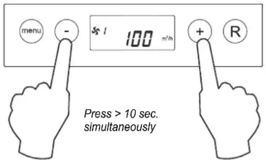

3 sec. visible
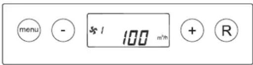
Operating mode
8.1 Trouble shooting
When the appliance control system detects a fault, it is indicated on the display with a spanner symbol, possibly together with a fault code.
The appliance makes a distinction between a fault at which the appliance keeps running (limitedly) and a serious (locking) fault at which both fans are switched off.
In case of locking fault, the settings and readings menu is switched off as well and only the service menu is available.
The appliance remains in this fault mode until the problem in question has been solved. Then the appliance will reset itself (auto reset) and the display will once more show the operational mode.
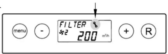
The fans are controlled on the basis of the value of the pressure sensors mounted on the control board. For each fan pressure hoses run to the control board. If these hoses are not connected as prescribed, or if they are leaking or blocked, a wrong pressure will be measured so the fans can no longer be controlled correctly. In case of doubt on the correct performance of the appliance, check the pressure hose connections
Fault E999
If, when the appliance is powered up directly to message E999 appears on the display, the mounted control board is not suitable for this appliance or the dip switches on the control board are set incorrectly.
For the location of the dip switches see § 10.2; position M
In that case, check whether the dip switches on the control board are set as shown in the drawing of the dip switches settings; if they are, and the message E999 still appears, then replace the control board by a board of the correct type.

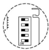
CWL-300 Excellent

CWL-400 Excellent
8.2 Display codes
Non-locking fault
When the appliance detects a non-locking fault, it will still keep running (limitedly). The display does show the fault symbol (spanner).

Locking fault
When the appliance detects a locking fault, it will no longer work. The (permanently lighted) display shows the fault symbol (spanner) together with fault code. The red LED on the multiple switch (if applicable) will be blinking. Contact the installer to remedy this fault. A locking fault cannot be remedied by taking the voltage from the appliance; first the fault must be solved.


| Fault code | Cause | Action appliance | Action installer |
| E100(non-locking fault) | Pressure sensor supply fan defective.Red pressure hoses blocked or “kinked”. | - Switches to constant rpm control.- The preheater switches on at outdoor temperatures below 0°C. | Take the voltage from the appliance.Check the red pressure hoses (and pressure tubes) for fouling, kinking and damage. |
| E101(non-locking fault) | Pressure sensor extract fan defective.Blue pressure hoses blocked or “kinked”. | - Switches to constant rpm control.- The preheater switches on at outdoor temperatures below 0°C. | Take the voltage from the appliance.Check blue pressure hoses (and pressure tubes) for fouling, kinking and damage. |
| E103(non-locking fault) | Bypass fault . | - None.(Current too low → stepper motor not correctly connected or effective; Current too high → short-circuit in wiring or stepper motor). | Take the voltage from the appliance.Check connection stepper motor; replace wiring or stepper motor. |
| E104(locking fault) | Extract fan defective. | - Both fans are switched off.- Preheater(s) is switched off.- If applicable: Postheater(s) is switched off.- Restart every 5 minutes. | Take the voltage from the appliance.Replace extract fan.But voltage back on appliance; Fault will automatically be reset.Check cabling. |
| E105(locking fault) | Supply fan defective. | - Both fans are switched off.- Preheater(s) is switched off.- If applicable: Postheater(s) is switched off.- Restart every 5 minutes. | Take the voltage from the appliance.Replace.Put voltage back on appliance; Fault will automatically be reset.Check cabling. |
| E106(locking fault) | The temperature sensor that measures the outdoor temperature is defective. . | - Both fans are switched off.- Preheater(s) is switched off.- Bypass closes and is blocked. | Take the voltage from the appliance.Replace temperature sensor.Put voltage back on appliance; fault will automatically be reset. |
| E107(non-locking fault) | The temperature sensor that measures the temperature of the extract air is defective. | - Bypass closes and is blocked. | Take the voltage from the appliance.Replace indoor temperature sensor. |
| E108(non-locking fault) | If present: The temperature sensor that measures the external temperature is defective. | - Postheater is switched off.- If applicable: Geo heat exchanger is switched off. | Replace external temperature sensor. |
| E111(non-locking fault) | If present: The RH-sensor that measures the humidity is defective. | - Appliance continues to operate | Take the voltage from the appliance.Replace RH-sensor. |
| E999(locking fault) | Dip switches on control board not set correctly. | - Appliance does nothing; red fault LED on multiple switch is not activated either. | Put dip switches incorrect position. (see § 8.1). |
Note!
If mode 2 of a multiple switch does not work, the modular connector of the multiple switch has been connected the wrong way round. Cut off one of the RJ connectors to the multiple switch and mount a new connector the other way round.
9.1. Filter cleaning
User maintenance is limited to periodically cleaning or replacing the filters. The filter only has to be cleaned when that is indicated on the display (it shows the text „FILTER“) or, if a multiple switch with filter indication is mounted, when the red LED at the switch lights up.


The filters must be replaced every year. It is not permitted to use the appliance without filters.
Cleaning or replacing the filters:
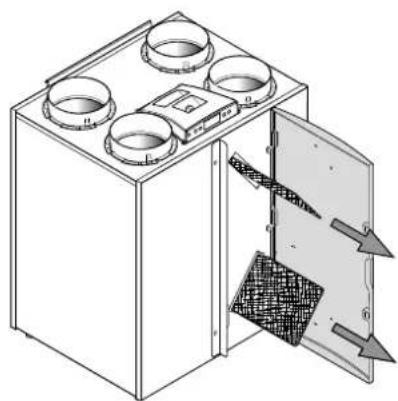
1 - Press the '-' key for 5 seconds.
- Open the filter door.

2 Remove the filters. Remember in what way the filters are taken out. (Clean side of the filter in the direction of heat exchanger).
natural_image
Technical line drawing of a four-cylinder air vent system with internal components and airflow direction arrows (no text or labels)3 Clean the filters.

natural_image
Simple line drawing of a desk lamp with a curved arm and a wall-mounted panel (no text or symbols)4 Place the filters back the same way as they were taken out.

natural_image
Isometric line drawing of a microwave oven with four circular fans and a door, showing internal structure and airflow direction (no text or symbols)5 Close the filter door.
- Switch on the appliance by pressing the key '-' during 5 seconds.

the 6 After the filters have been cleaned or replaced, press the "R" key for 5 seconds to reset the filter indication. The text "FILTER" will blink briefly to confirm that the filters have been reset. Also when the message "FILTER" has not yet appeared on the display, a filter reset can be carried out. the "counter" will be reset to zero.

After the filter reset, the text "FILTER"; disappears, the light at the multiple switch is off and the display is back to operating mode.


9.2 Maintenance
Installer maintenance includes cleaning the heat exchanger and fans. Dependent on the conditions, this must done about once every three years.
1 Switch off the appliance on the control panel (Press the '-' key for 5 seconds; the appliance will be switched off through software) and switch off the power.
Open the filter door.

2 Remove the filters.

natural_image
Technical line drawing of a four-tiered air conditioner unit with cooling fins and venting (no text or symbols)3 Remove the move the front cover.

natural_image
Technical line drawing of a multi-chamber industrial furnace or cooling unit with multiple circular cavities and a central vent (no text or symbols)4 Remove the heat exchanger. Be careful not to damage the foam parts in the appliance.

natural_image
Technical line drawing of a mechanical device with multiple circular components and an open door, showing internal structure without any text or symbols.5 Rinse the exchanger with hot water (max. 55 °C) and a regular detergent. Rinse the exchanger with hot water.

natural_image
Technical line drawing of a mechanical component with pipe fittings and a water drop symbol (no text or labels)6 Take off the display cover.
Note! First disconnect the connectors on the rear of the display cover.

7 Remove 4 pressure hoses and 3 connectors from the board.
8 Slide the fan assembly out of the appliance.

natural_image
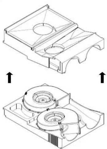
Technical line drawing of a mechanical housing with internal components and a separate view showing internal structure (no text or symbols)9 Place the fan assembly on a flat surface with the pressure hoses facing up. Remove the red and blue pressure hose without black mark from the pressure tubes mounted in the fan assembly. Turn over the foam assembly so the section with the pressure hoses is facing down.

10 Now the fan assembly can carefully be split so the two fans are accessible. Make sure the fans remain in the lower fan section!
natural_image
Technical line drawing of a mechanical component with two views showing internal structure and assembly (no text or symbols)11 Clean the fans with a soft brush. Make sure the balancing weights do not shift!

natural_image
Technical line drawing of a mechanical device with two circular components and a screwdriver (no text or symbols)12 Replace the separated part of the fan assembly and reconnect the loose pressure hoses to the pressure tubes. Make sure no dirt enters the pressure tubes!
13 Place the complete fan assembly back into the appliance.
14 Reconnect the pressure hoses and the fan cables to the board. Note the marking sticker on the pressure sensor for the correct position of the pressure hoses. Refer to the sticker in the appliance for the correct position of the connectors.
15 Remount the display cover and reconnect the loose connectors on the rear of the display cover.
16 Place the heat exchanger back into the appliance.
17 Place the front cover.
18 Place the filters back into the appliance with the clean side facing the exchanger.
19 Close the filter door.
20 Switch on the power supply.
21 Switch on the appliance on the control panel (pres key "for 5 seconds.-").
22 After cleaning the filter or placing a new filter, reset the filter indication by pressing the key "R" for 5 seconds.
10.1 Basic diagram
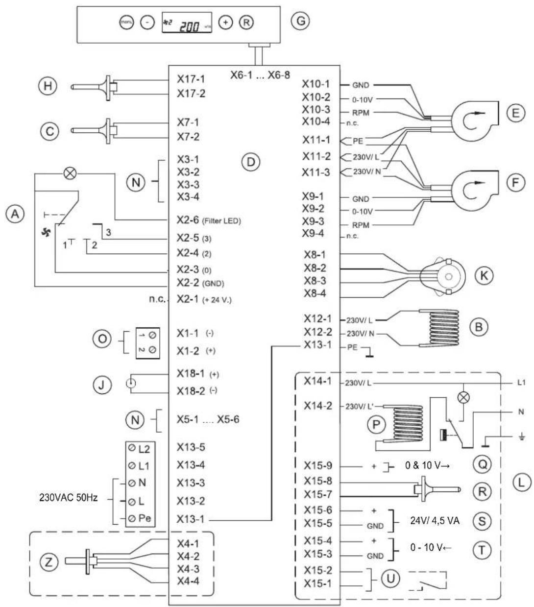
A = Multiple switch
B = Preheater
C = Outdoor temperature sensor
D = Control board
E = Supply fan
F = Extract fan
G = Control panel
H = Indoor temperature sensor
J = Service connector
K = Valve motor bypass
L = Connections accessories
N = Not applicable
O = Ebus connector (polarity sensitive)
(not suitable for 230V!)
P = Postheater
Q = Output 0-10 V
R = Sensor postheater or outdoor sensor geo heat exchanger
S = 24 volt connector
T = Input 0-10 V (or make contact)
U = Make contact or input 0-10 V)
Z = RH-sensor (option)
10.2 Wiring diagram
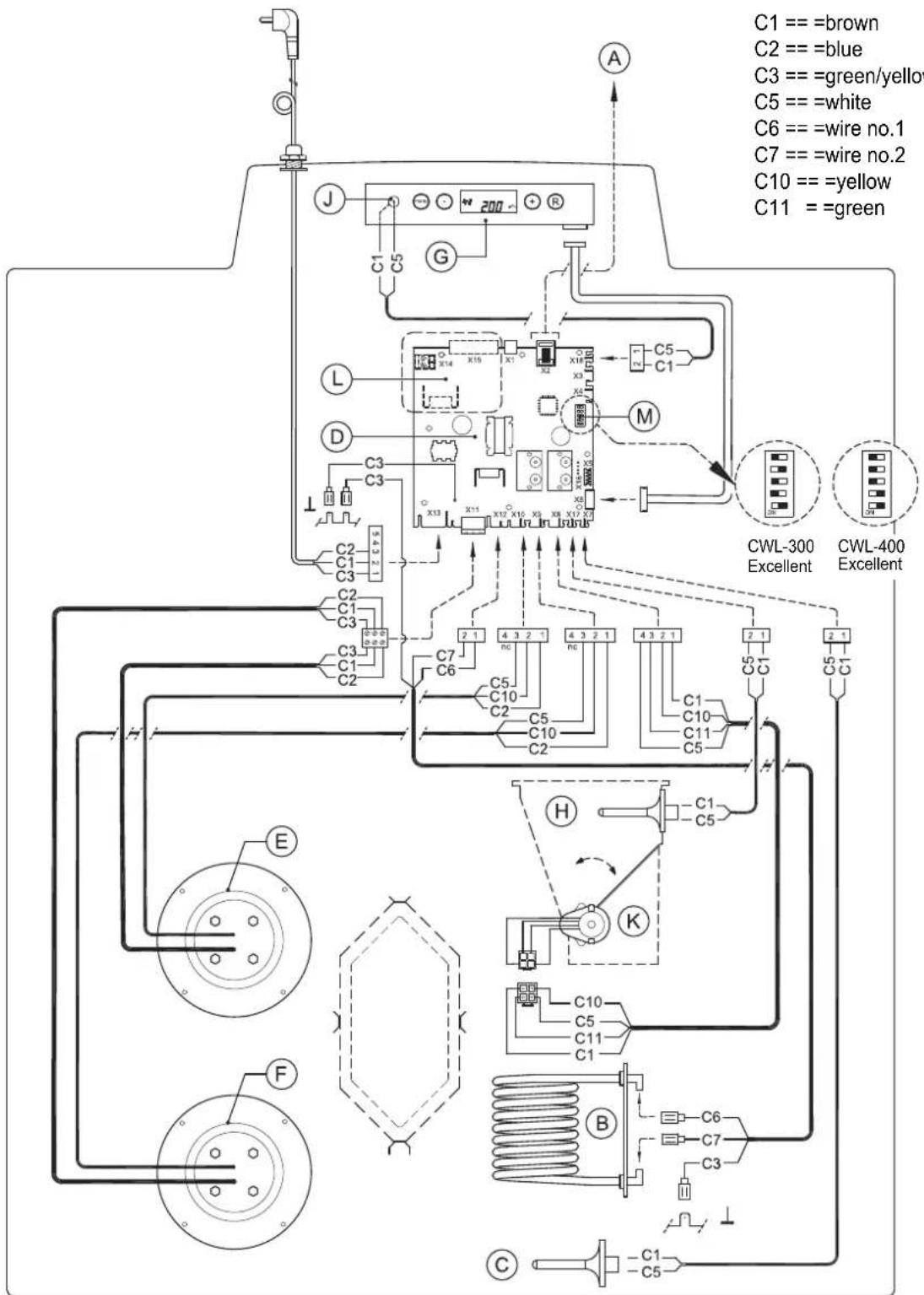
A = Connection for multiple switch
B = Preheater
C = Outdoor temperature sensor
D = Control board
E = Supply fan
F = Extract fan
G = Control panel
H = Indoor temperature sensor
J = Service connector
K = Valve motor bypass
L = Extra connectors
M = Dip switches for appliance selection
11.1 Connectors
Connector X1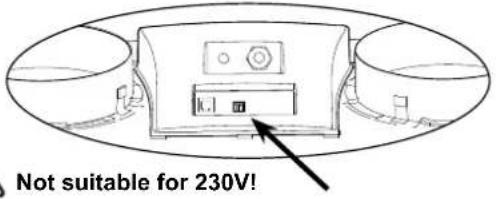 | eBus connector X1Two-pole screw connector.Set ex factory as eBus connector; =parameter =8 in the Settings menu (see §11.3). Only suitable for low voltage.Note: This connector is polarity-specific. |
Connector X2 | Modular connector X2 for rpm controlModular connector type RJ-12.Only suitable for low voltage |
Connector X14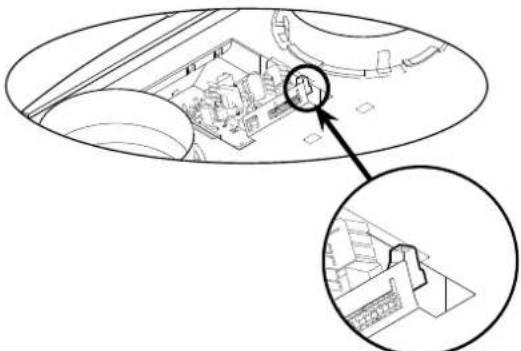 | Connector X14 for connecting postheater or additional pre-heaterTwo-pole =screw =connector =(accessible =after =taking =off =dis cover).Ex factory this connector is not activated; after changing para-meter =13 =in =the =settings =menu =of =“0” =to =“1” =(preheater (postheater), this connector can be used for connecting the pos-theater or preheaterMaximum rated power is 1000W.Note: The postheater temperature sensor must also be con- nected to X15-7 and X15-8.Use the =additionally mounted =pull =relief =in =the =display =co feed the 230 V cable to the postheater. |
Connector X15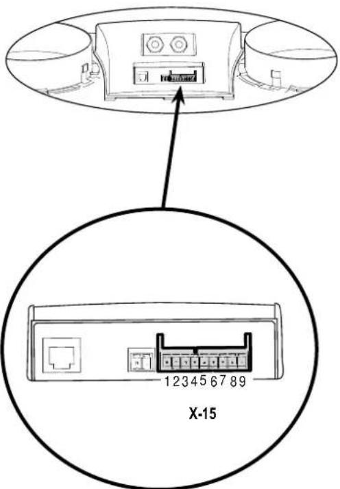 | Connector X15 (9-pole) for connecting special versions |
| Connection=Application | |
| 1 & 2(input 1)Stepnr. 15 = 0: normally open contact (= factory setting) §11.6)Stepnr. 15 = 1: 0 - 10V input 1; X15-1=GND & 15 - 2 = 0 - 10V (see §11.8)Stepnr. 15 = 2: normally closed contactStepnr. 15 = 3: input 1/ bypass open →12V; bypass closed →0VStepnr. 15 = 4: input 1/ bypass open →0V; bypass closed →1 2 V | |
| 3 & 4(input 2)Stepnr. 21 = 0: normally open contactStepnr. 21 = 1: 0 - 10V input (= factory setting) (see §11.8).Stepnr. 21 = 2: normally closed contactStepnr. 21 = 3: input 2/ bypass open →12V; bypass closed→0VStepnr. 21 = 4: input 2/ bypass open →0V; bypass closed →12V | |
| 5 & 6Conn. 24 volt, 4.5 VA max. (5 = ground, 6 = +) | |
| 7 & 8Connection postheater sensor or and outdoor geo heat exchanger | |
| 9Control signal valve 0 or 10 V (9 = +, 5 = ground) |
11.2 Connection examples multiple switch
A multiple switch can be connected to the modular connector X2 of the CWL-300/400 Excellent. This modular connector X2 is directly accessible at the rear of the display cover (see §11.1) without having to take it off.
11.2.1 Multiple switch with filter indication

A = CWL-300/400 Excellent
B = Multiple switch with filter indication
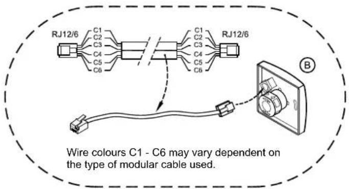
Note: For the modular cable use, the "tab" of both modular connectors must be mounted facing the mark on the modular cable.
11.2.2 Wireless remote control (without filter indication)

A = CWL-300/400 Excellent
B = Receiver for wireless remote control
C = Transmitter with 4 settings (e.g. kitchen)
D = Any additional 4-settings transmitters (A maximum of 6 transmitters can be signed on to 1 receiver)
11.2.3 Additional multiple switch with filter indication

A = CWL-300/400 Excellent
B1 = Multiple switch with filter indication
B2 = Additional multiple switch with filter indication
C = Splitter
11.2.4 Additional multiple switch with wireless remote control

A = CWL-300/400 Excellent
B = Multiple switch with filter indication
C = Receiver for wireless remote control
D = Transmitter with 2 settings
E = Splitter
11.3 Couple CWL-300/400 Excellent through eBus contact; all appliances equal air flow rate
Important:

Because of polarity sensitivity, always connect contacts X1-1 to X1-1 and contacts X1-2 to X1-2. Never connect X1-1 and X1-2.
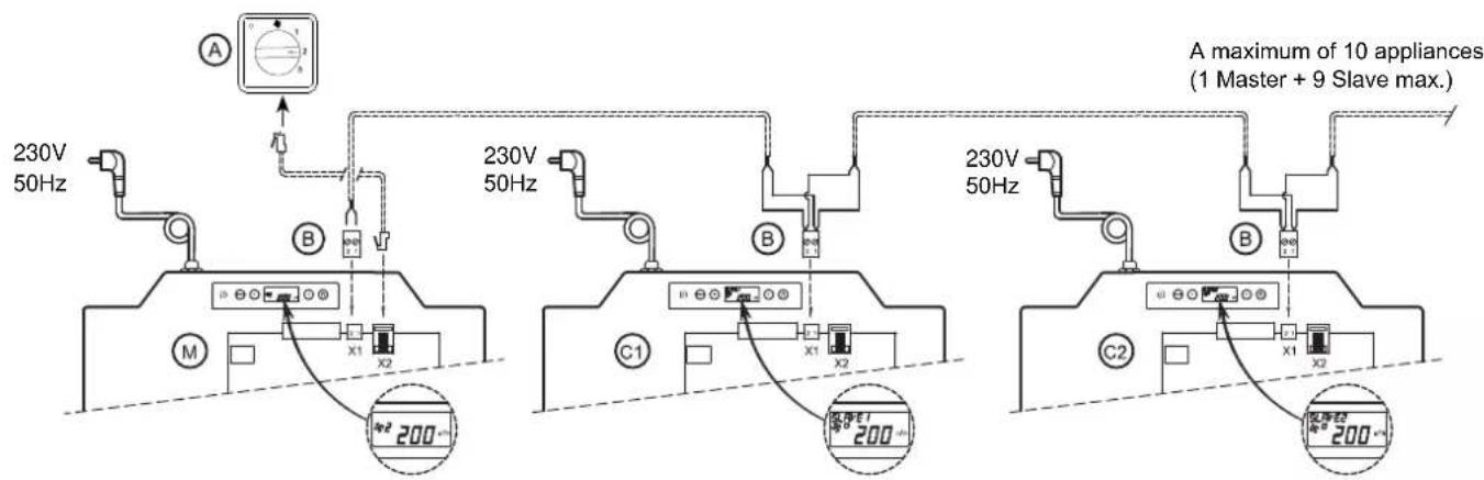
For M (Master):
Set parameter 9 to 0 (= factory setting).
Display shows ventilation mode 1, 2 or 3.
For C1 (Slave1):
set parameter 9 to 1 (= Slave 1).
Display always shows ventilation mode □.
For C2 (Slave2):
Set parameter 9 to 2 (= Slave 2).
Display always shows ventilation mode □.
A = Multiple switch
B = 2-pole connector
M = CWL-300/400 Excellent (Master)
C1 t/m C* = CWL-300/400 Excellent (Slave); couple not more than 10 appliances through Ebus
All CWL-appliances have the same air flow rates as the CWL-300/400 set as "Master".
| Step nr. | Description | Factory setting | Range |
| 8 | Communication type | eBus | 0t (= Opentherm)eBus |
| 9 eBus address | 0 | 0 = master1- 9 = slave 1 - 9 | |
11.4 Wiring diagram postheater connection or extra preheater
The electrical connections of the postheater and the extra preheater are the same; the only difference is that the postheater has an additional temperature sensor that must be wired to connector X15. Please refer to the mounting instructions that came with the heater for more extensive information regarding installation of the postheater or the extra preheater.
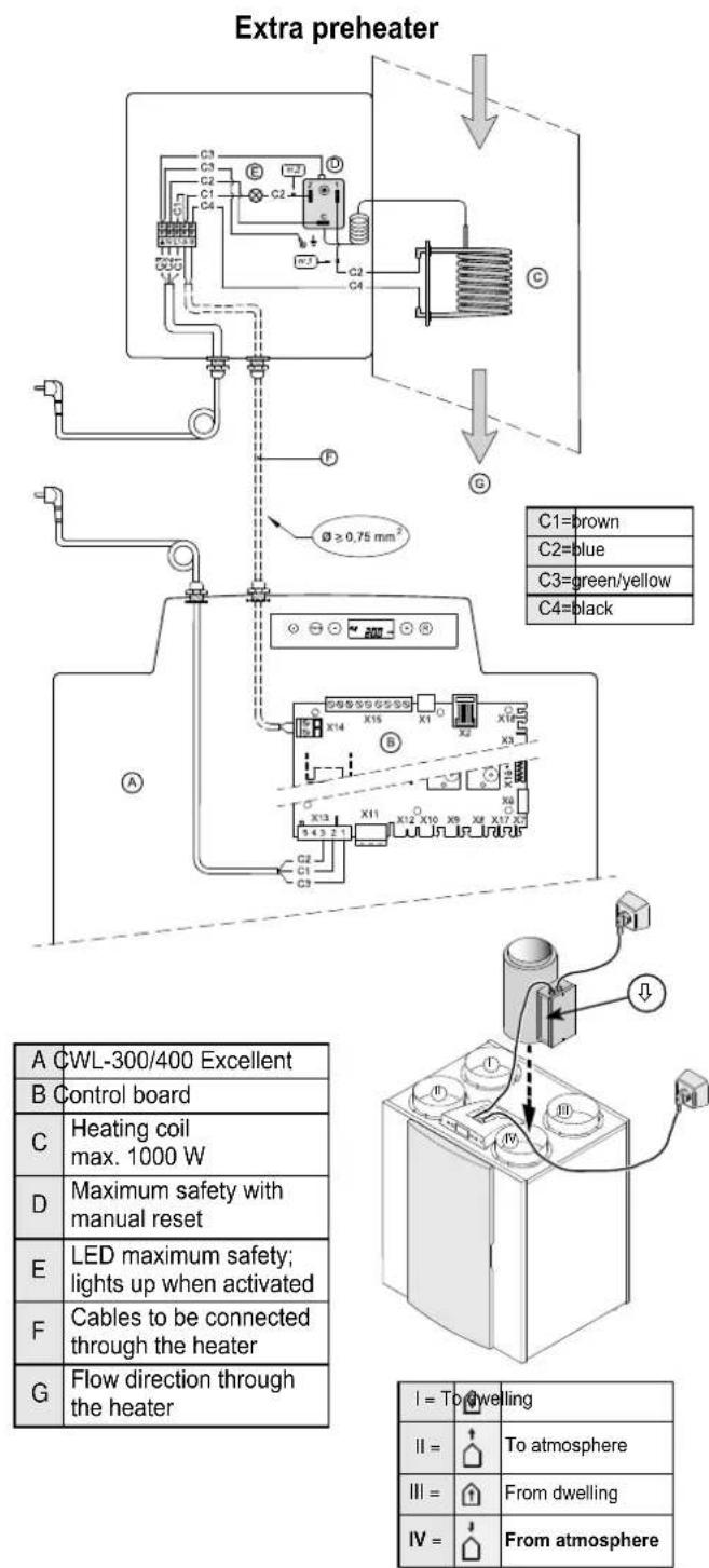
| Step nr.=Description=Factory setting=Range | ||
| 13 Heater | 0 | 0 = Off |
| 1 = Preheater | ||
| 2 = Postheater | ||

| Stepnr.= | Description=Factory setting=Range | ||
| 13 | Heater | 0 | 0 = Off1 = Preheater2 = Postheater |
| 14 | Temp. postheater | 21°C | 15°C - 30°C |
| I = To dwelling | |
| II = | To atmosphere |
| III = | From dwelling |
| IV = | From atmosphere |
11.5 Connection example geo heat exchanger
An den CWL-300/400 Excellent kann ein Erdwärmetauscher angeschlossen werden.
Der Erdwärmetauscher kann an den Anschluss Nr. 5 (GND) und Nr. 9 (+) des 9-poligen Steckers X15 angeschlossen werden. Dieser 9-polige Stecker ist direkt an der Hinterseite der Displayhaube erreichbar, ohne dass die Displayhaube demontiert werden muss.
Beim Anschluss des Erdwärmetauschers ist es nicht mehr möglich, ein Nachheizregister an den CWL-300/400 anzuschließen!
PRINCIPLE OF GEO HEAT EXCHANGER

flowchart
graph TD
    A["Input"] --> B["Process Unit"]
    B --> C["Flow Path ①"]
    B --> D["Flow Path ②"]
    B --> E["Flow Path ③"]
    B --> F["Flow Path ④"]
    B --> G["Flow Path ⑤"]
    B --> H["Flow Path ⑥"]
    B --> I["Flow Path ⑦"]
    B --> J["Flow Path ⑧"]
    B --> K["Flow Path ⑨"]
    style A fill:#f9f,stroke:#333
    style B fill:#ccf,stroke:#333
    style C fill:#cfc,stroke:#333
    style D fill:#fcc,stroke:#333
    style E fill:#cff,stroke:#333
    style F fill:#ffc,stroke:#333
    style G fill:#cfc,stroke:#333
    style H fill:#fcc,stroke:#333
    style I fill:#ffc,stroke:#333
    style J fill:#fcc,stroke:#333
    style K fill:#ffc,stroke:#333
I = To dwelling

II = To atmosphere

A = CWL-300/400 Excellent
B = Control board
C = Three-way valve 24 volt, control 0 - 10 V
D = Geo hear exchanger
E = Heat exchanger in CWL-300/400 Excellent
F = Outdoor temperature sensor (10 kΩ)
III = From dwelling

IV = From atmosphere

CONNECTION DIAGRAM OF GEO HEAT EXCHANGER
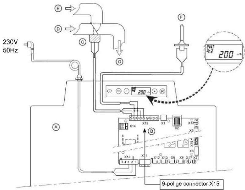
A = CWL-300/400 Excellent
B = Control board
C = Three-way valve 24 Volt (max. 4,5 VA); control 0 - 10 V
D = Air from the heat exchanger
E = Outside air
F = Outdoor temperature sensor (10 kΩ)
G = Air to the CWL-300/400 Excellent
When using a geo heat exchanger, parameter 27 must be changed from "OFF" to "ON". When the air is routed through the geo heat exchanger, the CWL-300/400 Excellent display shows the text "EWT".
| Step no.=Description=Factory setting=Range | |||
| 27 Switching on geo heat exchanger OFF | ON =Switched onOFF =Switched off | ||
| 28 | Minimum temperature geo heat exchanger | 5°C | 0 - 10°C |
| 29 | Maximum temperature geo heat exchanger | 25°C | 15 - 40°C |
11.6 Connecting external switch contact
An external switch contact (e.g. switch or relay contact) can be connected to the CWL-300/400 Excellent. This external switch contact can be connected to connections no. 1 and no. 2 of 9-pole connector X15; this 9-pole connector is directly accessible at the rear of the top without having to dismount the display cover (see also §11.1).
If a second input is required as external switch contact, if necessary connections no. 3 and no. 4 of the 9-pole connector X15, which as standard are preprogrammed as 0-10 volt input, can be reprogrammed as second input switch contact. Changing parameter 21 from "0" to "1" will turn this 0-10 V input into an input make contact. When using two switch inputs, switch contact 1 (X15-1 & X15-2) always takes priority over switch contact 2 (X15-3 & X15-4).

A = CWL-300/400 Excellent
B = Control board
C = Contact connected to switch input 1; for instance a switch or a relay contact
D = Display CWL-300/400 Excellent (text "CN1" appears when contact C is closed.)
Modifying parameter 18 enables, when closing the input external switch contact 1 X15-1 and X15-2, five different situations for the extract fan to be set; dependent on the setting of parameters 19 and 20, the supply and extract fans can run at various flow rates (highest flow rate is shown on the display).
| Setting Parameter 18 | Function conditions | Situation supply fan extract fan | Setting parameters 19 and 20 | Action supply or extract fan when closing contact inputs X15-1 & X15-2 | |
| 0 (factory setting) | Contact input 115-1 & X15-2 closed | No action possible because contact input 1 has not been activated yet (parameter 18 is still at 0) | |||
| 1 | Contact input 115-1 & X15-2 closed | Action dependent on setting supply fan (parameter 19) and extract fan (parameter 20) | 0 | Fan switches off | |
| 2 | Contact input 115-1 & X15-2 closedSatisfies bypass conditions for valve open ^1 | 1 | Fan minimum flow rate ( 50m^3/h ) | ||
| 2 | Fan to flow rate mode 1 | ||||
| 3 | Contact input 115-1 & X15-2 closed | The bypass valve opens^1) ; automatic bypass control in CWL-300/400Excellent is overruled; action fans dependent on parameters 19 & 20. | 3 | Fan to flow rate mode 2 | |
| 4 | Fan to flow rate mode 3 | ||||
| 5 | Fan to flow rate multiple switch | ||||
| 4 | Contact input 115-1 & X15-2 closed | The bedroom valves^2) opens.Bedroom valve 24 volt is connected to X15-5 (24V GND)X15-6 (24V +) and X15-9 (0-10 V control); action fans dependent on parameters 19 & 20. | 6 | Fan to maximum flow rate | |
| 7 | No fan activation | ||||
1) Bypass conditions opening valve: - outdoor temperature is higher than 10^ C
- temperature from atmosphere is at least lower than temperature from dwelling
- temperature from dwelling is higher than the preset bypass temperature (parameter 5)
2) Not in the delivery program
When connections X15-3 and X15-4 are programmed as switch input 2, parameters 24, 25 and 26 can be used to set the various situations the same as for contact input 1. When closing contact input 2, the display shows the text "CN2".
11.7 Connection to 0-10 V input
The CWL-300/400 Excellent can be equipped with an external provision with 0-10 volt control) (e.g. humidity sensor or CO_2 sensor). This external provision can be connected to pins no. 3 and no. 4 of 9-pole connector X15; this 9-pole connector is directly accessible at the rear of the top without having to dismount the display cover (see also §11.1).
Connections X15-3 and X15-4 are set as standard as 0 - 10 V input; it is activated as standard. Parameter 21 is set "1" ex factory. When the connected provision is active, the display shows the message V2. The minimum and maximum voltage for connected provisions can be set between 0 and 10 volt with parameter 22 (minimum voltage) and 23 (maximum voltage). The minimum voltage for parameter 22 cannot be set higher than the voltage set for parameter 23; the maximum voltage for parameter 23 cannot be set higher than the voltage set for parameter 22.

A = CWL-300/400 Excellent
B = Control board
C = Provision connected to 0-10 V input; for instance a humidity sensor or a CO_2 sensor.
Connected provision has its own power supply.
D = Display CWL-300/400 Excellent (text "V2" appears when the provision is active on input 2.)
If a second 0-10 V input is required, if necessary connections no. 1 and no. 2 of the 9-pole connector X15, standard preprogrammed as switch contact, can be reprogrammed to a second input 0-10 V. Modifying parameter 15 from "0" to "1" makes this input into a proportional 0-10 V input. When using two 0 - 10 V inputs, the 0 - 10 V input with the highest flow rate always takes precedence.
| Ex factory activated 0 - 10 V input (when active, the display shows the text “V2”) | ||||
| Connection =Parameter=Description=Adjusting range=Factory setting | ||||
| X15-3 & X15-4 | 21 do/ do not activate 0 - 10 V input | 1 = Switched on0 = Switched off | 1 | |
| 22 minimum voltage 0 - 10 volt=0.0 volt - 10.0 volt=0.0 volt | ||||
| 23 | maximum voltage 0 - 10 volt | 0.0 volt - 10.0 volt | 10.0 volt | |
If connection X15-1 and X15-2 are programmed as second 0-10 V input, parameters 15, 16 and 17 can be used to modify the various situations the same as for the standard 0-10 V input. When the provision is active on the optional second 0-10 V input, the display shows the text "V1".
11.8 Connection RH (huminity) - sensor

A = CWL-300/400 Excellent
B = Control board
C = RH (huminity) - sensor
D = Cable supplied with RH sensor
E = Duct from dwelling
C1 == =brown
C2 == =blue
C3 == =green/yellow
| Step nr.=Description=Factory setting=Range | |||
| 30 | Activating RH-sensor | OFF | OFF = not activeON = active |
| 31 Sensitivity | 0 | +2 most insensitive+1 ↑0 default setting RH-sensor-1 ↓-2 least sensitive | |
12.1 Exploded view

| * Temperature sensor resistance table NTC 10k | |||||
| -20°C = 96358Ω=1 | 1°C = 19037Ω | 16°C = 15056Ω | 21°C = 11990Ω=2 | 6°C = 9612Ω=35°C = | 6535Ω=60°C = 2490Ω |
| -10°C = 55046Ω=1 | 2°C = 18202Ω | 17°C = 14414Ω | 22°C = 11493Ω=2 | 7°C = 9224Ω=40°C = | 5330Ω=70°C = 1753Ω |
| 0°C = 32554Ω=13 | °C = 17368Ω | 18°C = 13772Ω | 23°C = 10995Ω=2 | 8°C = 8835Ω=45°C = | 4372Ω=80°C = 1256Ω |
| 5°C = 25339Ω=14 | °C = 16533Ω | 19°C = 13130Ω | 24°C = 10498Ω=2 | 9°C = 8447Ω=50°C = | 3605Ω=90°C = 915Ω |
| 10°C = 19872Ω=1 | 5°C = 15698Ω | 20°C = 12488Ω | 25°C = 10000Ω=3 | 0°C = 8059Ω=55°C = | 2989Ω=100°C = 677Ω |
Modifications reserved
Wolf GmbH continuously strives after improvement of products and reserves the right to change the specifications without prior notice.
| No. Article description Article code | ||
| 1 Filter kit 2x G4 filter (standard version) 1669013 | ||
| Filter kit 1x G4 & 1x F7 1669014 | ||
| 2 Fan CWL-300 /400 Excellent (1 pcs) 2137965 | ||
| 3 Temperature sensor 2745155 | ||
| 4 Control panel 2745156 | ||
| 5 Heat exchanger CWL-300 Excellent 2071761 | ||
| Heat exchanger CWL-400 Excellent 2071545 | ||
| 6 Motor bypass valve 2745157 | ||
| 7 Bypass valve 2745158 | ||
| 8 Control board (When replacing, note the correct dip switch settings; see §8.1 2745159 | ||
| 9 Heating coil 1000 W preheater 2745160 | ||
| 10 | Cable with power plug 230 volt with display cover* | 2745161 |
| 11 | Filter door left | 1800137 |
| Filter door right | 1800138 | |
| 12 | Front cover right | 1800139 |
| Front cover left | 1800140 | |
* The mains cable has a print connector.
When replacing it, always order a replacement mains cable Wolf
To avoid dangerous situations, a damaged mains should only be replaced by a qualified person!
12.2 Notes
| STEP NO. | DESCRIPTION | FACTORY SETTING | ADJUSTING RANGE | STEP | DISPLAY TEXT + SYMBOLS |
| 01 | Air flow rate mode CWL-300 Exc : mode | 50 m3/h=0 m | ^3/h or 50 m3/h | [IMAGE] | |
| Air flow rate mode CWL-400 Exc. : mode | 50 m3/h=0 m | ^3/h or 50 m3/h | |||
| 02 | Air flow rate mode CWL-300 Exc : mode 1=100 m | ^3/h=50 m | ^3/h - 300 m3/h | 5 m3/h | [IMAGE] |
| Air flow rate modet WL-400 Exc. : mode 1=100 m | ^3/h=50 m | ^3/h - 400 m3/h | |||
| 03 | Air flow rate mode CWL-300 Exc : mode 2=150 m | ^3/h=50 m | ^3/h - 300 m3/h | 5 m3/h | [IMAGE] |
| Air flow rate mode CWL-400 Exc. : mode 2=200 m | ^3/h=50 m | ^3/h - 400 m3/h | |||
| 04 | Air flow rate mode CWL-300 Exc : mode 3=225 m | ^3/h=50 m | ^3/h - 300 m3/h | 5 m3/h | [IMAGE] |
| Air flow rate mode CWL-400 Exc. : mode 3=300 m | ^3/h=50 m | ^3/h - 400 m3/h | |||
| 05 | Bypass temperature | 22,0 °C | 15,0 °C - 35,0 °C | 0,5 °C | BYPASS [IMAGE] |
| 06 | Bypass hysterese | 2,0 °C | 0,0 °C - 5,0 °C | 0,5 °C | BY HYS [IMAGE] |
| 07 | Operation bypass valve=0 | 0 = (= Automatic)1 = (= Bypass valve closed)2 = (= Bypass valve open) | BYPASS [IMAGE] | ||
| 08 | Communication | eBUS | Ot (= Opentherm)eBUS | OT/BUS | |
| 09 | Bus address | 0 | 0 - 9 (0 = Master) | BUSADR | |
| 10 | Central heating +heat recover | OFF | OFF (= Central heating+heat rec. off)ON (= Central heating+heat rec. on) | CV+WTW | |
| 11 | Imbalance permissible | ON | OFF (= flow rate sup. equals extract)ON (= imbalance permissible) | [IMAGE] | |
| 12 | Fixed imbalance | 0 m ^3/h=-100 m | ^3/h to 100 m3/h | 1 m3/h | [IMAGE] |
| 13 | Heater | 0 | 0 = (= off)1 = (= preheater)2 = (= postheater) | HEATER [IMAGE] | |
| 14 | Temperature postheater | 21,0 °C | 15,0 °C - 30,0 °C | 0,5 °C | HEATER [IMAGE] |
| 15 | Selection input 1 | 0 | 0 = (= normally open contact)1 = (= 0 - 10V input)2 = (= normally closed contact)3 = (= input 1/ bypass open → 12V; = bypass closed→ 0V)4 = (= input 1/ bypass open → 0V; = bypass closed→ 12V) | V1 | |
| 16 | Minimum voltage input 1 | 0,0 V | 0 Volt - 10 Volt | 0,5 V | V1 MIN |
| 17 | Maximum voltage input 1 | 10,0 V | 0 Volt - 10 Volt | 0,5 V | V1 MAX |
| 18 | Conditionsswitching input 1 | 0 | 0 (off)1 (on)2 (= On if conditions bypassopen satisfied)3 (= Bypass control)4 (= Bedroom valve) | CN1 | |
| 19 | Supply fan modeswitching input 1 | 5 | 0 (= Input fan off)1 (= Absolute min. flow rate 50m3/h)2 (= Flow rate mode 1)3 (= Flow rate mode 2)4 (= Flow rate mode 3)5 (= Multiple switch6 (= Maximum flow rate)7 (= no fan activation) | CN1 [IMAGE] [IMAGE] | |
| STEP NO. | DESCRIPTION | FACTORY SETTINGS | ADJUSTING RANGE | STEP | DISPLAY TEXT + SYMBOLS |
| 20 | Extract fan mode switching input 1 | 5 | 0 (= Extract fan off)1 (= Absolute min. flow rate 50m^3/h )2 (= Flow rate mode 1)3 (= Flow rate mode 2)4 (= Flow rate mode 3)5 (= Multiple switch)6 (= Maximum flow rate)7 (= no fan activation) | CN1 [IMAGE] | |
| 21 | Selection input 2=1 | 0 = (= normally open contact)1 = (= 0 - 10V input)2 = (= normally closed contact)3 = (= input 2/bypass open → 12V; bypass closed → 0V)4 = (= input 2/bypass open → 0V; bypass closed → 12V) | V2 | ||
| 22 | Minimum voltage input 2 | 0,0 V | 0,0 Volt - 10,0 Volt | 0,5 V | V2 MIN |
| 23 | Maximum voltage input 2=10,0 V =0,0 Volt- 10,0 Volt | =0,5 V= V2 MAX | |||
| 24 | Conditions switching input 2 | 0 | 0 (off)1 (on)2 (= On if conditions bypass open satisfied)3 (= Bypass control)4 (= Bedroom valve) | CN2 | |
| 25 | Supply fan mode switching input 2 | 5 | 0 (= Input fan off)1 (= Absolute min. flow rate 50m^3/h )2 (= Flow rate mode 1)3 (= Flow rate mode 2)4 (= Flow rate mode 3)5 (= Multiple switch)6 (= Maximum flow rate)7 (= No input fan activation) | CN2 [IMAGE] | |
| 26 | Extract fan mode switching input 2 | 5 | 0 (= Extract fan off)1 (= Absolute min. flow rate 50m^3/h )2 (= Flow rate mode 1)3 (= Flow rate mode 2)4 (= Flow rate mode 3)5 (= Multiple switch)6 (= Maximum flow rate)7 (= No extract fan activation) | CN2 [IMAGE] | |
| 27 | Geo heat exchanger=OFF | OFF (= Valve control geo heat exchanger off)ON (= Valve control geo heat exchanger on) | EWT | ||
| 28 | Minimum temperature geo heat exchanger (Below this temperature the valve opens.) | 5,0 °C=0,0 °C | - 10,0 °C | 0,5 °C | EWT T-[IMAGE] |
| 29 | Maximum temperature geo heat exchanger (Above this temperature the valve opens.) | 25,0 °C | 15,0 °C - 40,0 °C | 0,5 °C | EWT T+ [IMAGE] |
| 30 | H-sensor | OFF | OFF (= RH-sensor not active)ON (= RH-sensor active) | ||
| 31 | Sensitivity RH-sensor | 0 | +2 most sensitive+1 ↑0 default setting RH-sensor-1 ↓-2 least sensitive | ||
| Productdatasheet conform Ecodesign (EU), nr. 1254/2014 (Annex IV) | |||||
| Supplier: | Wolf GmbH | ||||
| Model: | CWL 300 Excellent | ||||
| Climate zone | Type of control | SEC-Value in kWh/m2/a | Energyclass (SEC) | The annual electricity consumption (AEC) in kWh | The annual heating saved (AHS) in kWh |
| Average | Manual -37,52 A 308 4403 | ||||
| Clock -38,38 A 294 4425 | |||||
| 1 Sensor (RH/CO2/VOC) -40,01 A 269 4469 | |||||
| 2 or more Sensors (RH/CO2/VOC) -42,88 A+ 216 4557 | |||||
| Cold | Manual -80,12 A+ 845 6720 | ||||
| Clock -81,19 A+ 832 6754 | |||||
| 1 Sensor (RH/CO2/VOC) -83,25 A+ 806 6821 | |||||
| 2 or more Sensors (RH/CO2/VOC) -86,97 A+ 753 6955 | |||||
| Warm | Manual -13,12 F 263 2317 | ||||
| Clock -13,86 E 250 2329 | |||||
| 1 Sensor (RH/CO2/VOC) -15,24 E 224 2352 | |||||
| 2 or more Sensors (RH/CO2/VOC) -17,62 E 171 2398 | |||||
| Type of ventilation unit: Ventilation unit with heat recovery | |||||
| Fan: | Variable speed EC fan | ||||
| Type of heat exchanger: | Recuperative plastic cross-counterflow heatexchanger | ||||
| Thermal efficiency: | 86% | ||||
| Maximum flow rate: | 300 m3/h | ||||
| Electric power input: | 92 W | ||||
| Sound power level Lwa: | 44 dB(A) | ||||
| Reference flow rate : | 210 m3/h | ||||
| Reference pressure difference: | 50Pa | ||||
| Specific Power Input (SEL): | 0,21 W/m3/h | ||||
| Control factor: | 1,0 in combination with manual switch | ||||
| 0,95 in combination with clock | |||||
| 0,85 in combination with 1 sensor | |||||
| 0,65 in combination with 2 or more sensors | |||||
| Leakage*: | Internal | 0,8% | |||
| External | 2,1% | ||||
| Filterwarning: | On the display of the ventilation unit / Manual switch / clock control.Attention! For optimal energy efficiency and a proper operation a regular filter inspection, cleaning or replacement is necessary. | ||||
| Internet address for Assembly instructions: | http://www.wolf-heiztechnik.de/downloads/download-center/montage-und-bedienungsanleitungen/ | ||||
| Bypass: | Yes; 100% Bypass | ||||
* Measurements executed by TNO according to the EN 13141-7 standard (TNO-report TNO 2013 M10230, Februari 2013)
| Classification from 1 January 2016 | |
| SEC klasse (“average climate”) | SEC in kWh/m2/a |
| A+ (most efficient) | SEC < -42 |
| A | -42 ≤ SEC < -34 |
| B | -34 ≤ SEC < -26 |
| C | -26 ≤ SEC < -23 |
| D | -23 ≤ SEC < -20 |
| E | -20 ≤ SEC < -10 |
| F | -10 ≤ SEC < 0 |
| G (least efficient) | 0 ≤ SEC |
| Productdatasheet conform Ecodesign (EU), nr. 1254/2014 (Annex IV) | |||||
| Supplier: | Wolf GmbH | ||||
| Model: | CWL 400 Excellent | ||||
| Climate zone | Type of control | SEC-Value in kWh/m2/a | Energyclass (SEC) | The annual electricity consumption (AEC) in kWh | The annual heating saved (AHS) in kWh |
| Average | Manual -36,26 A 346 4371 | ||||
| Clock -37,23 A 331 4395 | |||||
| 1 Sensor (RH/CO2/VOC) -39,06 A 301 4442 | |||||
| 2 or more Sensors (RH/CO2/VOC) -42,27 A+ 240 4536 | |||||
| Cold | Manual -78,55 A+ 883 6672 | ||||
| Clock -79,75 A+ 868 6703 | |||||
| 1 Sensor (RH/CO2/VOC) -82,04 A+ 838 6780 | |||||
| 2 or more Sensors (RH/CO2/VOC) -86,16 A+ 777 6924 | |||||
| Warm | Manual -12,03 F 301 2301 | ||||
| Clock -12,87 E 286 2313 | |||||
| 1 Sensor (RH/CO2/VOC) -14,44 E 256 2338 | |||||
| 2 or more Sensors (RH/CO2/VOC) -17,13 E 195 2388 | |||||
| Type of ventilation unit: | Ventilation unit with heat recovery | ||||
| Fan: | Variable speed EC fan | ||||
| Type of heat exchanger: | Recuperative plastic cross-counterflow heatexchanger | ||||
| Thermal efficiency: | 85% | ||||
| Maximum flow rate:: | 400 m3/h | ||||
| Electric power input: | 142 W | ||||
| Sound power level Lwa: | 48 dB(A) | ||||
| Reference flow rate : | 280 m3/h | ||||
| Reference pressure difference: | 50Pa | ||||
| Specific Power Input (SEL): | 0,24 W/m3/h | ||||
| Control factor: | 1,0 in combination with manual switch | ||||
| 0,95 in combination with clock | |||||
| 0,85 in combination with 1 sensor | |||||
| 0,65 in combination with 2 or more sensors | |||||
| Leakage*: | Internal | 0,4% | |||
| External | 1,3% | ||||
| Filterwarning: | On the display of the ventilation unit / Manual switch / clock control.Attention! For optimal energy efficiency and a proper operation a regular filter inspection, cleaning or replacement is necessary. | ||||
| Internet address for Assembly instructions: | http://www.wolf-heiztechnik.de/downloads/download-center/montage-und-bedienungsanleitungen/ | ||||
| Bypass: | Yes; 100% Bypass | ||||
* Measurements executed by TNO according to the EN 13141-7 standard (TNO-report TNO - 060 - DTM - 2013 - 01161, May 2013)
| Classification from 1 January 2016 | |
| SEC klasse (“average climate”) | SEC in kWh/m2/a |
| A+ (most efficient) | SEC < -42 |
| A | -42 ≤ SEC < -34 |
| B | -34 ≤ SEC < -26 |
| C | -26 ≤ SEC < -23 |
| D | -23 ≤ SEC < -20 |
| E | -20 ≤ SEC < -10 |
| F | -10 ≤ SEC < 0 |
| G (least efficient) | 0 ≤ SEC |
DECLARATION OF CONFORMITY (according to ISO/IEC 17050-1)
No: 3063041
Manufacturers: Wolf GmbH
A d d r e s s :
D-84048 Mainburg
Industriestr. 1
Product: Comfort domestic ventilation unit
with heat recovery
CWL- 300/400 Excellent
The product described above complies with the following documents:
DIN EN 12100 Part 1 and 2; 04/2004
DIN EN ISO 13857; 06/2008
DIN EN 349; 09/2008
EN 60335 Part 1; 02/2007
EN 60730; 06/2009
EN 61000-6-2;02/2007
EN 61000-6-3; 03/2006
EN 61000-3-2; 03/2010
EN 61000-3-3; 06/2009
Under the provisions of the following directives:
2006/95/EWG (low voltage directive)
2004/108/EWG (EMC directive)
RoHS 2011/65/EU(substances directive)
2009/125/EG (EU ErP-directive)
The product bears the CE label:
CE
Mainburg, 24.02.11
Gerdewan Jacobs Technical Director

613745/B
Wolf GmbH • Postfach 1380 • 84048 Mainburg • Tel. 08751/74-0 • Fax 08751/741600 • Internet: www.wolf-heiztechnik.de WOLF Klima- und Heiztechnik GmbH • Eduard Haas Str. 44 • 4034 Linz • Tel. 0732/385041-0 • Internet: www.wolf-heiztechnik.at
- Installation Instructions
- HEAT-RECOVERY-UNIT
- Standards
- General information
- Reference symbols
- Safety instructions
- Intended use
- Scope of delivery
- Connections and dimensions CWL-300/400 Excellent
- CWL-300/400 Excellent, right-handed version
- CWL-300/400 Excellent, left-handed version
- Exploded view appliance
- Description
- Bypass conditions
- Frost protection
- Version
- Installation general
- Placing the appliance
- Connecting the condensate discharge
- Connecting ducts
- Electric connections
- Connecting the power plug
- Warning
- Connecting the multiple switch
- Connecting eBus connector
- General explanation control panel
- Operating mode
- Status system fan
- Display air flow rate
- Message text for operating mode
- Settings menu
- Warning:
- Readout menu
- Service menu
- Switching the appliance on and off
- Switching on
- Switching off:
- Setting the air flow rate
- Important:
- Other settings installer
- Factory setting
- Trouble shooting
- Fault E999
- Display codes
- Non-locking fault
- Locking fault
- Filter cleaning
- Cleaning or replacing the filters:
- Maintenance
- Basic diagram
- Wiring diagram
- Connectors
- Connection examples multiple switch
- Multiple switch with filter indication
- Wireless remote control (without filter indication)
- Additional multiple switch with filter indication
- Additional multiple switch with wireless remote control
- Couple CWL-300/400 Excellent through eBus contact; all appliances equal air flow rate
- Wiring diagram postheater connection or extra preheater
- Connection example geo heat exchanger
- Connecting external switch contact
- Connection to 0-10 V input
- Connection RH (huminity) - sensor
- Exploded view
- Modifications reserved
- Notes
- DECLARATION OF CONFORMITY (according to ISO/IEC 17050-1)
- CE
Marque : WOLF
Modèle : CWL-2-325
Catégorie : Pompe à chaleur