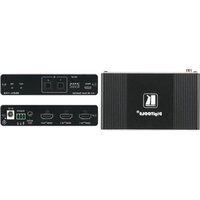
VS-211X - Routeur Kramer - Notice d'utilisation et mode d'emploi gratuit
Retrouvez gratuitement la notice de l'appareil VS-211X Kramer au format PDF.


| Type de produit | Routeur vidéo matriciel 2x1 |
| Marque | Kramer |
| Modèle | VS-211X |
| Nombre d'entrées | 2 (composite, S-Video, ou composante) |
| Nombre de sorties | 1 |
| Connecteurs d'entrée | 2x RCA (composite), 2x S-Video, 2x RCA (composante) |
| Connecteurs de sortie | 1x RCA (composite), 1x S-Video, 1x RCA (composante) |
| Type de commutation | Électronique, sélection par bouton-poussoir |
| Bande passante vidéo | 400 MHz (-3 dB) |
| Rapport signal/bruit | > 70 dB |
| Impédance d'entrée | 75 ohms |
| Impédance de sortie | 75 ohms |
| Alimentation | 12 V DC, 500 mA (adaptateur secteur inclus) |
| Dimensions (L x P x H) | 160 x 100 x 40 mm |
| Poids | 0,4 kg |
| Fonctions principales | Sélection d'entrée manuelle, commutation sans clic, maintien de la synchronisation |
| Entretien et nettoyage | Nettoyer avec un chiffon doux et sec. Ne pas utiliser de solvants. |
| Sécurité | Utiliser uniquement l'adaptateur fourni. Ne pas ouvrir le boîtier. |
| Pièces détachées et réparabilité | Pas de pièces détachées disponibles. Contacter le SAV Kramer. |
| Informations générales | Conçu pour une utilisation en rack ou en bureau. Température de fonctionnement : 0-40°C. |
FOIRE AUX QUESTIONS - VS-211X Kramer
Questions des utilisateurs sur VS-211X Kramer
0 question sur cet appareil. Repondez a celles que vous connaissez ou posez la votre.
Poser une nouvelle question sur cet appareil
Téléchargez la notice de votre Routeur au format PDF gratuitement ! Retrouvez votre notice VS-211X - Kramer et reprennez votre appareil électronique en main. Sur cette page sont publiés tous les documents nécessaires à l'utilisation de votre appareil VS-211X de la marque Kramer.
MODE D'EMPLOI VS-211X Kramer

Scan for full manual
VS-211X and VS-411X Quick Start Guide
This guide helps you install and use your VS-211X / VS-411X for the first time.
Go to www.kramerav.com/downloads/VS-411X to download the latest user manual and check if firmware upgrades are available.
Step 1: Check what's in the box
VS-211X / VS-411X 4K Auto Switcher
1 Power adapter and cord
4 Rubber feet
1 Quick start guide
Step 2: Get to know your VS-211X / VS-411X

flowchart
graph TD
    A["PROG."] --> B["2x1 4K Auto Switcher"]
    C["SETUP"] --> D["2x1 4K Auto Switcher"]
    E["IN"] --> F["2x1 4K Auto Switcher"]
    G["OUT"] --> H["VS-211x"]
    I["ON"] --> J["VS-211x"]

flowchart
graph TD
    A["6"] --> B["HDMI IN 1"]
    C["7"] --> D["HDMI IN 2"]
    E["8"] --> F["AUDIO OUT"]
    G["9"] --> H["REMOTE"]
    I["10"] --> J["SW DC"]


The terms HDMI, HDMI High-Definition Multimedia Interface, and the HDMI Logo are trademarks or registered trademarks of HDMI Licensing Administrator, Inc.
| # | Feature | Function |
| 1 | PROG Micro USB Connector | Connect to upgrade the firmware. |
| 2 | SETUP 4-way DIP-Switches | Set the operation DIP-switches (see Setting the DIP-Switches). |
| 3 | IN Buttons | Press to select an HDMI input (button lights orange). |
| 4 | OUT LED | Lights green when an HDMI output is connected. |
| 5 | ON LED | Lights green when the device receives power. |
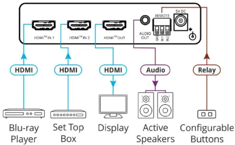
| 6 | HDMI ^TM IN Connectors | Connect to an HDMI source (2 for VS-211X, 4 for VS-411X). |
| 7 | HDMI ^TM OUT Connector | Connect to an HDMI acceptor. |
| 8 | AUDIO OUT3.5mm Mini Jack Connector | Connect to an unbalanced stereo audio acceptor. |
| 9 | REMOTE IN Terminal block Connector | Connect to contact closure switches by momentary contact between the desired pin and common GND pin to select an input. |
| 10 | 5V DC Power Connector | Connect to the power supply and to the mains electricity. |
Step 3: Install VS-211X / VS-411X
Install VS-211X / VS-411X using one of the following methods:
- Attach the rubber feet and place the unit on a flat surface.
- Fasten a bracket (included) on each side of the unit and attach it to a flat surface (see www.kramerav.com/downloads/VS-411X).
- Mount the unit in a rack using the recommended rack adapter (see www.kramerav.com/product/VS-411X).


- Ensure that the environment (e.g., maximum ambient temperature & air flow) is compatible for the device.
- Avoid uneven mechanical loading.
- Appropriate consideration of equipment nameplate ratings should be used for avoiding overloading of the circuits.
- Reliable earthing of rack-mounted equipment should be maintained.
• Maximum mounting height for the device is 2 meters.
Step 4: Connect the inputs and outputs
Always switch OFF the power on each device before connecting it to your VS-211X. For best results, we recommend that you always use Kramer high-performance cables to connect AV equipment to the VS-211X. VS-211X and VS-411X are identical except for the number of inputs.
flowchart
graph TD
    A["Blu-ray Player"] --> B["HDMI"]
    C["Set Top Box"] --> D["HDMI"]
    E["Display"] --> F["HDMI"]
    G["Active Speakers"] --> H["Audio"]
    I["Configurable Buttons"] --> J["Relay"]
    B --> K["HDMI™ IN 1"]
    D --> L["HDMI™ IN 2"]
    F --> M["HDMI™ OUT"]
    H --> N["REMOTE"]
    I --> O["5V DC"]
    K --> P["AUDIO OUT"]
    L --> Q["Audio"]
    M --> R["Audio"]
    N --> S["5V DC"]
    O --> T["5V DC"]
    P --> U["Relay"]
    Q --> V["Relay"]
    R --> W["Relay"]
Setting the DIP-Switches
DIP-switches 1, 2 and 3 are set to ON (down) by default and DIP-switch 4 is always set to OFF (up). DIP-switch changes take effect immediately.
| # | Feature | Dip-Switch Settings |
| 1 | Switching Mode | OFF (up) – Manual mode.ON (down) –Auto-switching mode. |
| 2 | Auto-switching Mode | OFF (up) – Priority switching mode: the device switches the source with the highest priority to the output.ON (down) – Last connected switching mode: the last detected active source is auto-switched to the output. |
| 3 | EDID lock | Off (up) – EDID Locked.On (down) – EDID parameters are passed-through. |
| 4 | Reserved for Factory Use | It is mandatory to keep set to OFF (up). |

For optimum range and performance use the recommended Kramer cables available at www.kramerav.com/product/VS-411X
Step 5: Connect the power
Connect the power cord to VS-211X / VS-411X and plug it into the mains electricity.
Safety Instructions (See www.kramerav.com for updated safety information).

Caution:
- For products with relay terminals and GPI\O ports, please refer to the permitted rating for an external connection, located next to the terminal or in the User Manual.
- There are no operator serviceable parts inside the unit.
Warning:
- Use only the power cord that is supplied with the unit.
- Disconnect the power and unplug the unit from the wall before installing.


Marque : Kramer
Modèle : VS-211X
Catégorie : Routeur