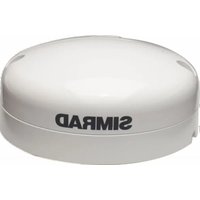
GS25 - Antenne GPS SIMRAD - Notice d'utilisation et mode d'emploi gratuit
Retrouvez gratuitement la notice de l'appareil GS25 SIMRAD au format PDF.


| Type de produit | Récepteur GPS marin |
| Marque | Simrad |
| Modèle | GS25 |
| Dimensions | 120 x 80 x 30 mm |
| Poids | 250 g |
| Matériau du boîtier | Plastique ABS résistant aux UV |
| Alimentation | 12 V DC, consommation 1,5 W |
| Connectique | Câble NMEA 0183 avec connecteur 5 broches |
| Fréquence de réception | L1 GPS, 1575,42 MHz |
| Précision de position | Moins de 2,5 m (typique) |
| Taux de mise à jour | 10 Hz |
| Fonctions principales | Positionnement GPS, sortie NMEA, assistance WAAS/EGNOS |
| Température de fonctionnement | -20 °C à +60 °C |
| Indice de protection | IPX7 (étanche jusqu'à 1 m pendant 30 min) |
| Entretien et nettoyage | Essuyer avec un chiffon doux et humide; éviter solvants |
| Sécurité | Respecter la tension d'alimentation; ne pas immerger au-delà de 1 m |
| Pièces détachées et réparabilité | Contacter le SAV Simrad; câble de remplacement disponible |
| Informations générales | Utilisation marine; compatible avec les traceurs Simrad et Lowrance |
FOIRE AUX QUESTIONS - GS25 SIMRAD
Questions des utilisateurs sur GS25 SIMRAD
0 question sur cet appareil. Repondez a celles que vous connaissez ou posez la votre.
Poser une nouvelle question sur cet appareil
Téléchargez la notice de votre Antenne GPS au format PDF gratuitement ! Retrouvez votre notice GS25 - SIMRAD et reprennez votre appareil électronique en main. Sur cette page sont publiés tous les documents nécessaires à l'utilisation de votre appareil GS25 de la marque SIMRAD.
MODE D'EMPLOI GS25 SIMRAD
LOWRANCE
SIMRAD
B&G
GPS Antenna
With built-in Heading
Sensor
Installation Guide
ENGLISH
natural_image
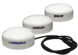
Three white circular sensors labeled LOWRANCE, SIMRAD, and B&G connected by a black cord (no additional text or symbols visible)www.lowrance.com | www.simrad-yachting.com | www.bandg.com
LOWRANCE
SIMRAD
B&G
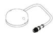
Supplied parts
Lowrance® Point-1 Simrad® GS25 B&G® ZG100
 |  |  |
 |  |  |
 |  |  |
 |  |  |
 | [TBTW] | [A3ZT] |
 |  |  |
| Attached NMEA 2000* Drop cable 1.2 m (4 ft) + NMEA 2000* Drop cable 4.5 m (15 ft) | NMEA 2000* Drop cable 4.5 m (15 ft) | |
Antenna mounting location

Surface mount the antenna Surface mount: Surface cable run
1

2
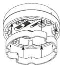
3

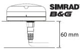
4

natural_image
Pure electrical circuit lines without any symbolsLOWRANCE
2
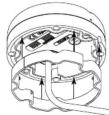


Pole mount (external cable)
1

2

3

4

5
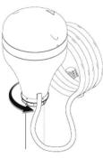
6
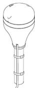
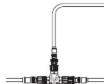
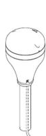
Pole mount (Internal cable)
1

2

3

5

4

[Non-Text]

| Specifications | |
| General | |
| Receiver type L1, C/A code, 1.575 GHz | frequency/L2 C/A code, 1.602 GHz frequency |
| Channels 32 channels | |
| Position update rate Up to 10 Hz (1,5,10) | |
| Horizontal accuracy 3 m (9.8 ft) | |
| Heading accuracy +/- 3" | |
| Rate of turn accuracy +/- 3" | |
| Roll/Pitch accuracy at 30° +/- 1° | |
| Cold start 50 sec | |
| Start-up time 3 sec | |
| Satellite reacquisition 5 sec | |
| Environmental | |
| Operating temperature -25°C to +60°C | (-13°F to +140°F) |
| Storage temperature -40°C to +85°C | (40°F to +185°F) |
| Splash proof IPX7 | |
| Humidity 40°C, 93% RH, operating | |
| Electrical | |
| Input voltage 9 V DC - 18 V DC | |
| Reverse polarity protection | Yes |
| Power consumption | < than 2 W |
| Current consumption | < 100 mA at 12 V DC |
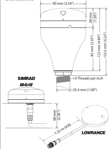
| Dimensions | 90 mm (diam) x 38 mm (height)3.54" (diam) x 1.50" (height) |
| Weight | 0.14 Kg (0.3 lbs) aprox |
| Power/Data cable | NMEA 2000* thru NMEA 2000* network |
| Antenna connector | NMEA 2000* Micro C |
| Mounting | Flush mount / Standard pole mount |
| Communications | |
| Data I/O Protocol | NMEA 2000* |
| NMEA 2000* PGNs | |
| PGN Number | PGN Title |
| 126992 | System time |
| 129025 | Position, Rapid update |
| 129026 | COG & SOG RU |
| 129029 | Position data |
| 129539 | GNS DOP |
| 129540 | GNS Satellites in view |
| 127258 | Magnetic variation |
| 127250 | Compass heading (Vessel heading) |
| 127251 | Rate of turn |
| 127257 | Attitude |
Compliance Statements
WARNING: The user is cautioned that any changes or modifications not expressly approved by the part responsible for compliance would void the user's authority to operate the equipment.
Navico declare under our sole responsibility that the product conforms with the requirements of:
- Comply with CE under RED 2014/53/EU Directive. - Comply with the requirements of level 2 devices of the Radiocommunications (Electromagnetic Compatibility) standard 2017. The relevant Declaration of Conformity is available in the following website under model documentation section: www.lowrance.com, www.simrad-yachting.com, www.bandg.com
*Reg. U.S. Pat. & Tm. Off, and ™ common law marks. Visit www.navico.com/Intellectual-property to review the global trademark rights and accreditations for Navico Holding AS and other entities.
Heading sensor calibration
The built in heading sensor will need to be calibrated before use to compensate for local magnetic fields on your vessel for accurate chart with radar overlay.
Auto Calibrate mode
Before the heading sensor calibration is started, make sure that there is enough open water around for the vessel to make multiple full turns. The calibration should be done in calm sea conditions and with minimal wind to obtain best results.
| A | Disconnect then reconnect the sensors NMEA 2000* cable. |
| B | Make two consecutive turns of 360 degrees. The completion of these two turns automatically activates the Auto Calibration procedure. |
| C | Continue with a smooth third turn and a quarter (of at least 390 degrees) within 2 to 5 minutes, to complete the calibration. |
| D | Calibration should be complete. If the time is outside the limits, the calibration is void and the radar overlay may not appear accurate on your chart. Repeat steps A-D if calibration fails. |
Calibration from a Multifunction display
Calibration can be performed from a compatible Multifunction display, instrument display or autopilot controller. For more information, refer to the documentation for your display unit.
Multiple heading sensors on the network
WARNING: Point-1 is a heading sensor and GPS antenna. By default, Point-1 is a heading sensor if there are no other heading sensors on the network. If there are two Point-1 units on the network, only one can be a heading sensor, the other will function as a GPS antenna. In this case, the Point-1 unit that is used as the heading sensor must be set to instance '1'.
If there is a Point-1 unit and another heading sensor on the network, such as Precision-9, the latter would be the heading sensor by default.
If you have multiple Simrad ^® GS25 or B&G ^® ZG100 heading sensors on the network, your MFD will only receive data from the heading sensor set as the compass source in the system.


flowchart
graph TD
    A["Connection"] --> B["LowRANCE"]
    B --> C["SIMRAD B&G"]
    C --> D["Terminal C"]
    D --> E["Terminal E"]
    E --> F["Terminal F"]
    F --> G["Terminal G"]
    G --> H["Terminal H"]
    H --> I["Terminal I"]
    I --> J["Terminal J"]
    J --> K["12V DC"]
    style A fill:#f9f,stroke:#333
    style B fill:#ccf,stroke:#333
    style C fill:#cfc,stroke:#333
    style D fill:#fcc,stroke:#333
    style E fill:#cff,stroke:#333
    style F fill:#ffc,stroke:#333
    style G fill:#f9f,stroke:#333
    style H fill:#ccf,stroke:#333
    style I fill:#cfc,stroke:#333
    style J fill:#fcc,stroke:#333
A Multifunction display
B Lowrance® Point -1 or Baja has molded cable 1.2 m (4 ft)
C Simrad® GS25 or B&G® ZG100 : Requires NMEA 2000® Drop cable (D)
D NMEA 2000 ^® drop cable max length 4.55 m (15 ft)
E 120 Ohm Terminator (male)
F 120 Ohm Terminator (female)
G Fuse (5 Amp)
H Switch
NMEA 2000® Power cable 1.8 m (6 ft)
J 12 V DC Power supply
Dimensions
Heading sensor application
| This sensor includes an electronic heading sensor to provide chart stabilization, course over ground at low speeds, and overlay of radar on charts. | ||
| √ | Acceptable performance for the application. | |
| × | A rate stabilized heading sensor such as Precision-9 will provide the most robust performance for demanding applications. | |
| Point-1GS25ZG100 | Precision-9 compass | |
| Radar Overlay | √ | √ |
| MARPA | × | √ |
| Autopilot InterfaceTM | × | √ |
Marque : SIMRAD
Modèle : GS25
Catégorie : Antenne GPS