
LiveSight - Équipement de navigation marine SIMRAD - Notice d'utilisation et mode d'emploi gratuit
Retrouvez gratuitement la notice de l'appareil LiveSight SIMRAD au format PDF.


| Type de produit | Sonar à balayage avant/vue latérale |
| Marque | Simrad |
| Modèle | LiveSight |
| Catégorie | Accessoires nautiques |
| Dimensions (L x l x h) | 11,5 x 6,5 x 4,5 cm |
| Poids | 450 g |
| Alimentation | 12 V CC, consommation 8 W |
| Fréquence du sonar | 455/800 kHz |
| Angle de balayage | 120° en avant, 60° de chaque côté |
| Profondeur maximale | 150 m |
| Compatibilité écran | Simrad NSS, NSO, GO series |
| Connectique | Connecteur Ethernet SonarHub |
| Fonctions principales | Balayage avant en temps réel, vue latérale, détection de poissons et structures |
| Installation | Montage sur tableau arrière ou support de sonde, câble de 6 m inclus |
| Matériau du boîtier | Plastique renforcé IPX7 |
| Température de fonctionnement | -10°C à 60°C |
| Entretien et nettoyage | Nettoyer avec un chiffon doux et eau savonneuse, rincer à l'eau douce |
| Précautions de sécurité | Déconnecter l'alimentation avant installation, éviter les chocs |
| Pièces détachées et réparabilité | Contacter le SAV Simrad pour toute réparation |
FOIRE AUX QUESTIONS - LiveSight SIMRAD
Questions des utilisateurs sur LiveSight SIMRAD
0 question sur cet appareil. Repondez a celles que vous connaissez ou posez la votre.
Poser une nouvelle question sur cet appareil
Téléchargez la notice de votre Équipement de navigation marine au format PDF gratuitement ! Retrouvez votre notice LiveSight - SIMRAD et reprennez votre appareil électronique en main. Sur cette page sont publiés tous les documents nécessaires à l'utilisation de votre appareil LiveSight de la marque SIMRAD.
MODE D'EMPLOI LiveSight SIMRAD
Compliance statements
Europe
Navico declares under our sole responsibility that the product conforms with the requirements of:
CE under EMC Directive 2014/30/EU
The relevant Declaration of Conformity is available on the following websites:
- www.lowrance.com
www.simrad-yachting.com
United States of America
Note: The user is cautioned that any changes or modifications not expressly approved by the party responsible for compliance could void the user's authority to operate the equipment
Australia and New Zealand
Navico declares under our sole responsibility that the product conforms with the requirements of:
level 2 devices of the Radiocommunications (Electromagnetic Compatibility) standard 2017
The relevant Declaration of Conformity is available on the following websites:
- www.lowrance.com
- www.simrad-yachting.com
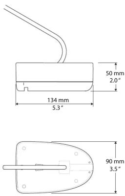
Dimensions
LOWRANCE
SIMRAD
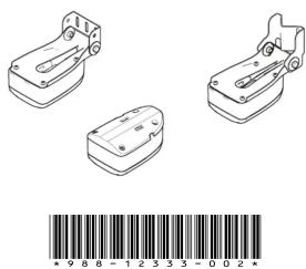
LiveSight transducer Installation Guide
Technical specifications
Note: The most up-to-date specifications are available at the product web site.
| Environmental | |
| Water temperature for operation | 0°C to +35°C(32°F to +95°F) |
| Storage temperature | -30°C to +70°C(-22°F to +158°F) |
| Physical | |
| Weight (without cable) | 0,614 kg(1.354 lbs.) |
| Cable length | 7,6 m (25 ft) |
| Mounting options | TransomTrolling motor shaft(forward-looking)Trolling motor(down-looking) |
Parts included



A. LiveSight transducer, incl. 7,6 m (25 ft) cable
B. Transducer bracket
C. Trolling motor adapter
D. Screws M4x8 Ph SS18-8 and washers (4x)
E. Transom mounting bracket
F. Screws #10x11/4" tap and washers (for transom bracket) (x3)
G. Pole adapter (for trolling motor shaft)
H. Hex flange bolts M6-1x12, SS18-8, and M6x1 serrated flange nut, 316SS (x2)
I. Screw M4x8 Ph SS18-8 and M4 316SS nylock nut
J. Clamp hose 20 SS (for trolling motor shaft) (x2)
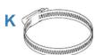
K. Clamp hose 72 SS (for trolling motor adapter)
L. Documentation
Trolling motor installation (down-looking)

Transom installation (down-looking)
→ Notes:
The transducer could lose bottom signal when the boat is on plane.
The transducer will not work while it is out of the water.
Mounting guidelines

Mirror the example if your boat has a counterclockwise propeller rotation.
Best mounting location:
A. undisturbed water flow
Avoid mounting:
B. behind planing strake
C. 1 m (3.3') to port (left) of propeller
D. within 7.5 cm (3") to starboard of propeller
E. close to trim tabs
Mount the transducer parallel to the water surface.


Installation

2

3

natural_image
Technical line drawing of a mechanical bracket with mounting holes and a close-up view of the base plate (no text or symbols)
5
Apply a marine high-grade above- or below-waterline sealant/adhesive compound to the pilot holes.
6

natural_image
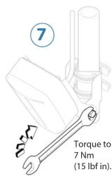
Illustration of a wrench tool with a numbered step indicator (7), no text or symbols presentTorque to 7 Nm (15 lbf in).

Recommended pilot holes for self-tapping screws:
| Material #10 screw | |
| Soft materials e.g. plywood ∅ 3.7-4.0 mm (5/32") | |
| Hard materials e.g. fiberglass, acrylic, hardwoods ∅ | 4.1-4.7 mm (3/16") |
| Aluminum ∅ 4.2-4.5 mm (0.173") |
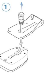
Trolling motor shaft installation (forward-looking)
natural_image
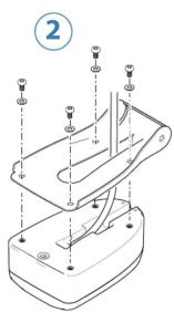
Technical diagram of a mechanical assembly with mounting holes and a base plate (no text or symbols)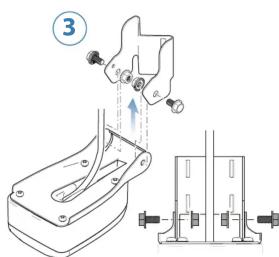
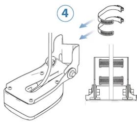
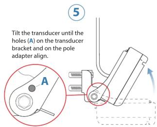
Install the screw and nylock nut to fix the transducer angle.


natural_image
Technical line drawing of a mechanical assembly with a screwdriver and cylindrical component (no text or symbols)
natural_image
Technical line drawing of a mechanical clamp or bracket assembly (no text or symbols)Marque : SIMRAD
Modèle : LiveSight
Catégorie : Équipement de navigation marine