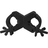
TPC-35S - Éclairage Eurolite - Notice d'utilisation et mode d'emploi gratuit
Retrouvez gratuitement la notice de l'appareil TPC-35S Eurolite au format PDF.


| Type de produit | Projecteur LED |
| Marque | Eurolite |
| Modèle | TPC-35S |
| Dimensions (L x l x h) | 25 x 20 x 15 cm |
| Poids | 1.5 kg |
| Alimentation | 100-240 V AC, 50/60 Hz |
| Consommation électrique | 35 W |
| Source lumineuse | LED RGB 3W |
| Angle de faisceau | 25° |
| Fonctions principales | Éclairage RGB, mode automatique, mode DMX 512 |
| Contrôle | DMX, pilotage autonome, maître/esclave |
| Entretien et nettoyage | Nettoyer avec un chiffon doux et sec. Ne pas utiliser de produits abrasifs. |
| Sécurité | Ne pas exposer à l'humidité ou aux projections d'eau. Utiliser uniquement en intérieur. |
| Pièces détachées et réparabilité | Contacter le service après-vente Eurolite pour toute réparation. |
| Informations générales | Utilisation sur scène, en discothèque ou pour des événements. |
FOIRE AUX QUESTIONS - TPC-35S Eurolite
Questions des utilisateurs sur TPC-35S Eurolite
0 question sur cet appareil. Repondez a celles que vous connaissez ou posez la votre.
Poser une nouvelle question sur cet appareil
Téléchargez la notice de votre Éclairage au format PDF gratuitement ! Retrouvez votre notice TPC-35S - Eurolite et reprennez votre appareil électronique en main. Sur cette page sont publiés tous les documents nécessaires à l'utilisation de votre appareil TPC-35S de la marque Eurolite.
MODE D'EMPLOI TPC-35S Eurolite
D TPC Klammer
Vor der ersten Inbetriebnahme zur eigenen Sicherheit die nachfolgenden Hinweise sorgfältig durchlesen. Die aktuellste Version erhalten Sie im Internet.
Sicherheitshinweise
Dieses Produkt hat das Werk in sicherheitstechnisch einwandfreiem Zustand verlassen. Um diesen Zustand zu erhalten und einen gefahrlosen Betrieb sicherzustellen, muss der Anwender die Sicherheitshinweise und die Warnvermerke unbedingt beachten, die in dieser Bedienungsanleitung enthalten sind. Bei Schäden, die durch Nichtbeachtung der Anleitung verursacht werden, erlischt der Garantieanspruch. Für daraus resultierende Folgeschäden übernimmt der Hersteller keine Haftung. Wird das Produkt anders verwendet als in dieser Bedienungsanleitung beschrieben, kann dies zu Schäden führen und der Garantieanspruch erlischt. Außerdem ist jede andere Verwendung mit Gefahren, wie z. B. Abstürzen etc. verbunden. Eigenmächtige Veränderungen am Produkt sind aus Sicherheitsgründen verboten.
Bestimmungsgemäße Verwendung
Die Klammer dient zur Installation von Projektoren, Lichteffekten etc. über ein Traversensystem. Die Maximalbelastung darf dabei niemals überschritten werden. Das Produkt ist für professionelle Anwendungen vorgesehen, z. B. Bühnen oder Diskotheken. Achten Sie bei der Montage, beim Abbau und bei der Durchführung von Servicearbeiten darauf, dass der Bereich unterhalb des Montageortes abgesperrt ist.
Installationshinweise
LEBENSGEFAHR! Bei der Installation sind insbesondere die Bestimmungen der BGV C1 und DIN 15922 zu beachten! Die Installation darf nur vom autorisierten Fachhandel ausgeführt werden. Vor der ersten Inbetriebnahme muss die Einrichtung durch einen Sachverständigen geprüft werden.
- Die Aufhängevorrichtung des Geräts muss so gebaut und bemessen sein, dass sie 1 Stunde lang ohne dauernde schädliche Deformierung das 10-fache der Nutzlast aushalten kann.
- Die Installation muss immer mit einer zweiten, unabhängigen Aufhängung, z. B. einem geeigneten Fangnetz, erfolgen. Diese zweite Aufhängung muss so beschaffen und angebracht sein, dass im Fehlerfall der Hauptaufhängung kein Teil der Installation herabfallen kann.
- Während des Auf-, Um- und Abbaus ist der unnötige Aufenthalt im Bereich von Bewegungsflächen, auf Beleuchterbrücken, unter hochgelegenen Arbeitsplätzen sowie an sonstigen Gefahrbereichen verboten.
- Der Unternehmer hat dafür zu sorgen, dass sicherheitstechnische und maschinentechnische Einrichtungen geprüft werden: a) Vor der ersten Inbetriebnahme und nach wesentlichen Änderungen vor der Wiederinbetriebnahme durch Sachverständige. b) Alle vier Jahre durch einen Sachverständigen im Umfang der Abnahmeprüfung. c) Mindestens einmal jährlich durch einen Sachkundigen.
- Das Gerät sollte außerhalb des Aufenthaltsbereiches von Personen installiert werden.
- Das Gerät muss außerhalb des Handbereichs von Personen installiert werden.
- Überkopfmontage erfordert ein hohes Maß an Erfahrung! Dies beinhaltet (aber beschränkt sich nicht allein auf) Berechnungen zur Definition der Tragfähigkeit, verwendetes Installationsmaterial und regelmäßige Sicherheitsinspektionen des verwendeten Materials und des Geräts. Versuchen Sie niemals, die Installation selbst vorzunehmen, wenn Sie nicht über eine solche Qualifikation verfügen, sondern beauftragen Sie einen professionellen Installateur. Unsachgemäße Installationen können zu Verletzungen und/oder zur Beschädigung von Eigentum führen.
- Hängend installierte Geräte können beim Herabstürzen erhebliche Verletzungen verursachen! Wenn Sie Zweifel an der Sicherheit einer möglichen Installationsform haben, installieren Sie das Gerät nicht!
-
Vergewissern Sie sich vor der Montage, dass die Montagefläche mindestens die 10-fache Punktbelastung des Eigengewichtes des Geräts aushalten kann.
-
Sichern Sie das Gerät bei Überkopfmontage immer mit einem geeigneten Sicherungsseil. Es dürfen nur Sicherungsseile gemäß DIN 56927, Schnellverbindungs-glieder gemäß DIN 56927, Schäkel gemäß DIN EN 1677-1 und BGV C1 Kettbiner eingesetzt werden. Die Fangseile, Schnellverbindungsglieder, Schäkel und Kettbiner müssen auf Grundlage der aktuellsten Arbeitsschutzbestimmungen (z. B. BGV C1, BGI 810-3) ausreichend dimensioniert sein und korrekt angewendet werden.
- Der maximale Fallabstand darf 20 cm nicht überschreiten. Ein Sicherungsseil, das einmal der Belastung durch Absturz ausgesetzt war oder beschädigt ist, darf nicht mehr als Sicherungsseil eingesetzt werden.
- Bei Überkopfmontage in öffentlichen bzw. gewerblichen Bereichen ist eine Fülle von Vorschriften zu beachten, die hier nur auszugsweise wiedergegeben werden können. Der Betreiber muss sich selbständig um die Beschaffung der geltenden Sicherheitsvorschriften bemühen und diese einhalten! Der Hersteller haftet nicht für Schäden, die durch unsachgemäße Installation und unzureichende Sicherheitsvorkehrungen verursacht werden!
Wartung
- Der Unternehmer hat dafür zu sorgen, dass sicherheitstechnische und maschinentechnische Einrichtungen geprüft werden: a) mind. alle vier Jahre durch einen Sachverständigen im Umfang der Abnahmeprüfung. b) mind. einmal jährlich durch einen Sachkundigen. Dabei muss unter anderem auf folgende Punkte besonders geachtet werden: a) Alle Schrauben, mit denen das Gerät oder Geräteteile montiert sind, müssen fest sitzen und dürfen nicht korrodiert sein. b) An Gehäuse, Befestigungen und Montageort (Decke, Wand) dürfen keine Verformungen sichtbar sein.
- Vorgeschriebene Prüfungsfristen beachten: a) Jährlich durch Sachkundigen. b) Alle vier Jahre durch Sachverständigen c) Vor jedem Gebrauch auf Bruch und Funktion durch den Anwender.
- Sollten Sie noch weitere Fragen haben, steht Ihnen Ihr Fachhändler jederzeit gerne zur Verfügung.
Technische Daten
| Artikel | Maximallast WLL (4-fach) | Gewicht | ∅ Rohr |
| TPC-10 59006856, 59006858 150 kg 0,3 kg 50 mm | |||
| TPC-15 5900685E, 5900685F | 150 kg | 0,3 kg | 50 mm |
| TPC-20 59006859 10 kg 0,03 kg | 20 mm | ||
| TPC-20S 5900685A 10 kg 0,03 kg | 20 mm | ||
| TPC-30 59006860, 59006862 | 500 kg | 0,5 kg | 50 mm |
| TPC-31 59006865, 59006867 | 500 kg | 0,6 kg | 50 mm |
| TPC-32 59006868, 59006869 | 200 kg | 0,4 kg | 50 mm |
| TPC-35 59006870, 59006872 | 500 kg | 0,9 kg | 50 mm |
| TPC-36 5900687A 200 kg 0,5 kg | 50 mm | ||
| TPC-50/35 59006925 150 kg 0.2 kg | 35/50 mm | ||
| TPC-50 59006800, 59006802 | 800 kg | 0,7 kg | 50 mm |
| TPC-51 59006848, 59006849 | 800 kg | 0,8 kg | 50 mm |
| TPC-53 59006811 500 kg 0,7 kg | 45-50 mm | ||
| TPC-55 59006845, 59006846 | 800 kg | 1,3 kg | 50 mm |
| TPC-56 59006850, 59006930 | 500 kg | 0,7 kg | 50 mm |
| TPC-56Q 59006851, 59006931 | 500 kg | 0,7 kg | 50 mm |
Technische Änderungen ohne vorherige Ankündigung und Irrtum vorbehalten. © 12.02.2020
D00120673, Version 4.2
EN TPC Coupler
For your own safety, please read this leaflet carefully before you initially start-up. You can find the latest update online.
Safety Instructions
This product has left our premises in absolutely perfect condition. In order to maintain this condition and to ensure a safe operation, it is absolutely necessary for the user to follow the safety instructions and warning notes written in this user manual. Damages caused by the disregard of this user manual are not subject to warranty. The dealer will not accept liability for any resulting defects or problems. If the product will be operated in any way different to the one described in this manual, it may suffer damages and the guarantee becomes void. Furthermore, any other operation may lead to dangers like crash etc. Please consider that unauthorized modifications on the adapter are forbidden due to safety reasons.
Operating Determinations
This coupler is designed for installing projectors, lighting effects etc. on a truss system. The maximum load must never be exceeded. This product is designed for professional use, e.g. on stages, in discotheques, theatres etc. Make sure that the area below the installation place is blocked when rigging, derigging or servicing.
Installation Instructions
DANGER TO LIFE! Please consider the DIN 15922 and the respective national norms during the installation! The installation must only be carried out by an authorized dealer! Before taking into operation for the first time, the installation has to be approved by an expert.
- The installation of the device has to be built and constructed in a way that it can hold 10 times the weight for 1 hour without any harming deformation.
- The installation must always be secured with a secondary safety attachment, e.g. an appropriate catch net. This secondary safety attachment must be constructed in a way that no part of the installation can fall down if the main attachment fails.
- When rigging, derigging or servicing the device staying in the area below the installation place, on bridges, under high working places and other endangered areas is forbidden.
- The operator has to make sure that safety-relating and machine-technical installations are approved by: a) an expert before taking into operation for the first time and after changes before taking into operation another time. b) an expert after every four year in the course of an acceptance test. c) a skilled person once a year.
- The device should be installed outside areas where persons may walk by or be seated.
- The device has to be installed out of the reach of people.
- Overhead rigging requires extensive experience, including (but not limited to) calculating working load limits, installation material being used, and periodic safety inspection of all installation material and the device. If you lack these qualifications, do not attempt the installation yourself, but instead use a professional structural rigger. Improper installation can result in bodily injury and or damage to property.
- Devices in hanging installations may cause severe injuries when crashing down! If you have doubts concerning the safety of a possible installation, do not install the device!
- Before rigging make sure that the installation area can hold a minimum point load of 10 times the device's weight.
- For overhead use, always install an appropriate safety bond. You must only use safety bonds complying with DIN 56927, quick links complying with DIN 56926, shackles complying with DIN EN 1677-1 and BGV C1 carbines. The safety bonds, quick links, shackles and the carbines must be sufficiently dimensioned and used correctly in accordance with the latest industrial safety regulations (e.g. BGV C1, BGI 810-3).
- The maximum drop distance must never exceed 20 cm. A safety rope which already hold the strain of a crash or which is defective must not be used again.
- For overhead rigging in public or industrial areas, a series of safety instructions have to be followed that this manual can only give in part. The operator must therefore inform himself on the current safety instructions and consider them. The manufacturer cannot be made liable for damages caused by incorrect installations or insufficient safety precautions!
Maintenance
- The operator has to make sure that safety-relating and machine-technical installations are inspected by: a) an expert after every four years in the course of an acceptance test. b) a skilled person once a year. The following points have to be considered during the inspection: a) All screws used for installing the devices or parts of the device have to be tightly connected and must not be corroded. b) There must not be any deformations on housings, fixations and installation spots (ceiling, suspension, trussing).
- Observe prescribed testing deadlines: a) Once a year by an expert. b) Every four years by a skilled person. c) Before every use for breakage and function by the operator.
- Should you have further questions, please contact your dealer.
Technical Specifications
| Item | Max. load WLL (4-fold) | Weight ∅ Tube |
| TPC-10 59006856, 59006858 150 kg 0.3 kg 50 mm | ||
| TPC-15 5900685E, 5900685F | 150 kg | 0.3 kg |
| TPC-20 59006859 10 kg 0.03 kg 20 mm | ||
| TPC-20S 5900685A 10 kg 0.03 kg 20 m | ||
| TPC-30 59006860, 59006862 | 500 kg | 0.5 kg |
| TPC-31 59006865, 59006867 | 500 kg | 0.6 kg |
| TPC-32 59006868, 59006869 | 200 kg | 0.4 kg |
| TPC-35 59006870, 59006872 | 500 kg | 0.9 kg |
| TPC-36 5900687A 200 kg 0.5 kg 50 mm | ||
| TPC-50/35 59006925 150 kg 0.2 kg 35/50 mm | ||
| TPC-50 59006800, 59006802 | 800 kg | 0.7 kg |
| TPC-51 59006848, 59006849 | 800 kg | 0.8 kg |
| TPC-53 59006811 500 kg 0.7 kg 45-50 mm | ||
| TPC-55 59006845, 59006846 | 800 kg | 1.3 kg |
| TPC-56 59006850, 59006930 | 500 kg | 0.7 kg |
| TPC-56Q 59006851, 59006931 | 500 kg | 0.7 kg |
Every information is subject to change without prior notice. © 12.02.2020 D00120673, version 4.2
Marque : Eurolite
Modèle : TPC-35S
Catégorie : Éclairage