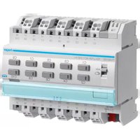
TYA610D - Chargeur électrique HAGER - Notice d'utilisation et mode d'emploi gratuit
Retrouvez gratuitement la notice de l'appareil TYA610D HAGER au format PDF.


| Type de produit | Thermostat d'ambiance programmable |
| Marque | Hager |
| Modèle | TYA610D |
| Dimensions (L x H x P) | 85 x 85 x 30 mm |
| Poids | 150 g |
| Alimentation | 2 piles alcalines AAA (fournies) |
| Affichage | Écran LCD rétroéclairé |
| Plage de température | 5 °C à 35 °C |
| Précision de mesure | ± 0,5 °C |
| Programmation | Hebdomadaire, jusqu'à 4 plages horaires par jour |
| Fonctions principales | Mode confort, réduit, hors gel, vacances |
| Entretien et nettoyage | Nettoyer avec un chiffon doux et sec. Ne pas utiliser de produits abrasifs. |
| Indice de protection | IP30 |
| Classe énergétique | IV (4%) |
| Compatibilité | Chauffage gaz, électrique, pompe à chaleur |
| Garantie | 2 ans |
| Pays d'origine | France |
FOIRE AUX QUESTIONS - TYA610D HAGER
Questions des utilisateurs sur TYA610D HAGER
0 question sur cet appareil. Repondez a celles que vous connaissez ou posez la votre.
Poser une nouvelle question sur cet appareil
Téléchargez la notice de votre Chargeur électrique au format PDF gratuitement ! Retrouvez votre notice TYA610D - HAGER et reprennez votre appareil électronique en main. Sur cette page sont publiés tous les documents nécessaires à l'utilisation de votre appareil TYA610D de la marque HAGER.
MODE D'EMPLOI TYA610D HAGER
:hager

EN
[Non-Text]
[Non-Text]
[Non-Text]
The image is too blurry to recognize any text content.
2.5%
(3)
The image is too blurry to recognize any text content.
50%
(五)
∴ m = 3/11
-
S
-
C
3
[Non-Text]
C
3
-
E
-
[Non-Text]
[Non-Text]
[Non-Text]
[Non-Text]
[Non-Text]
[Non-Text]
[Non-Text]
[Non-Text]
[Non-Text]
[Non-Text]
[Non-Text]
[Non-Text]
[Non-Text]
[Non-Text]
[Non-Text]
[Non-Text]
[Non-Text]
[Non-Text]
[Non-Text]
[Non-Text]
[Non-Text]
[Non-Text]
[Non-Text]
[Non-Text]
[Non-Text]
[Non-Text]
[Non-Text]
[Non-Text]
Safety instructions
Electrical equipment may only be installed and
assembled by a qualified electrician in accor-
dance with the relevant installation standards,
gazardines, Regulations, and others, safety and accident prevention regulations of the country
Failure to comply with these installation
instructions may result in damage to the
device, fire or other hazards.
Hazard due to electric shock. Disconnect before working on the device or load. Take into
account all circuit breakers that supply
dangerous voltages to the device or load.
Hazard due to electric shock. The device is not
cased for bare acidification of the thanks supply.
Hazard due to electric shock on the SELV/PEL
installation. Not suitable for switching SELV/
PELV Voltages.
Do connect only one motor per output. When connecting several motors, motors or devices
may be destroyed
Use drives with mechanical or electrical final
position switches only. Check final position
switches for correct adjustment. Observe motor manufacturer's data. The device could
get damaged.
Do not connect any three-phase motors. The
device could get damaged.
Observe the motor manufacturer's data regarding changes over time and may switch or tip
ing change over time and then cut off on a me.
These instructions are an integral component
of the product and must be retained by the end
user.
Design and layout of the device

Fig. 1: Example device variant 8/4gang
(1) Slide switch auto/
(2) KNX bus connection terminal
(3) Connections loads
(4) Labeling held (5) Illuminated as
(3) Translation programming button
output with status LED
(7) Connections for switching voltage
(8) Mains power supply connections (only 8gang)
With variants 4/2gang, 6/3gang and 10/5gang
the basic design corresponds to the 8/4gang device variant.
2017年1月1日
Function
and System information
This device is a product of KNX system and
corresponds to the KNX guidelines. Detailed
try. specialised knowledge obtained from RENT training courses is required for comprehension. The
planning, installation and commissioning of the
davics
[Non-Text]
Systemlink start-up into
The function of the device is software-dependent. The software is to be taken from the product
database. You can find the latest version of the
not product database, technical descriptions as well
on qu
EL
/ Easylink start-up; The function of the
The function of the device is configuration dependent. The configuration can also be done using
device
534-0
al This type of configuration is only possible with devices of the easylink system. Easylink stands for
easy, visually supported start-up. Preconfigured
Id standard functions are assigned to the in/outputs by means of a service module.
By 192
e Functional description
The device receives telegrams from sensors or other controlism via the IKNX installation hub and
switches electrical loads with its independent relay
contas
nt The C load variants are particularly suitable for
end on cur
[Non-Text]
[Non-Text]
tial-free contacts.
- Switching electric
AC for blinds, shutters, awnings and similar
1
60715 in the distribution box.
|
(6) Product characteristic
1
1
1
1
1
1
-
- Time switching functions
Functions in shutter/blind operation:
- Position can be started directly
- Stat position directly controllable
- Feedback of operating state, shutter position and slot adjustment
- 3 Alarms
[Non-Text]
Operation
Manual operation switch on/off
With the 8/4gang variants, control of the out-
puts is possible even without bus voltage when
ma
D
Bus of mains power supply is present. Push switch (i) to positive
- 本说明在《证券法》中载明了
Manual operation is switched on; the outputs can be controlled using the operation buttons
(6) independently of each other.
During manual operation, the controller is deac-
tivated via the RNA Bus
Systemlink start-up
Depending on the programming, the manual operation is either activated permanently or
for a time period configured via the application
software. If the manual operation is blocked via the application software, no activation takes
place.
Or:
- Move switch (1) to position auto.
The manual operation is switched off. Opera-
ton takes place solely via the KNA Bus. The output adopts the position predefined by the
bus controller.
together. Motors, hangings and the
Operation takes place per output by brief repeated
presses on the operation button (table 1)
CAUTION!
Risk of destruction due to simultane-
bus pressing of the buttons for UP and DOWN if a motor is connected when
the motor is in unprogrammed state!
Motors, hangings and the device may
be destroyed
Always only press one button in Connect device


electric shock! Fig 3: Installation/deinstallation with plug-in
An electric shock can be lethal! terminals
CAUTION!
Impermissible heating if the load of
the device is too high!
The device and the connected cables
may get damaged in the connection
at our
DO NOT EXCEED THE MAXIMUM CURRENT carrying capacity!
(No text)
CAUTION!
Risk of destruction if parallel connec-
tion of several motors on one output!
Final position switches could fuse
together. Motors, hangings and the device may be destroyed!
Do connect only one motor per
output!
The Ground Truth image displays a single, solid horizontal line. According to Rule 2 (UNDERSCORE & LINE RULES), this is a stylistic or background line, not a placeholder underscore. Therefore, the OCR result must ignore it and output nothing or only meaningful text. The provided OCR content is "____", which consists of four underscores. This is an incorrect interpretation of the line as a placeholder, violating the rule that stylistic lines must be ignored. The OCR has hallucinated underscores where none should exist based on the GT's visual context. Hence, the OCR result is inconsistent with the Ground Truth.
Installing the appliance
☐ Observe temperature range. Provide sufficient
- Mount device gets DIN rail in accordance with coding.
DIN EN 60715.
■ 本报告
Connect device
L1 L2 a
| : | - | - | - |
□是□否
□ 0 0 □ 0 0 0 0 0 0 0
ch dca' be ca' cl cl
□ 0101 0204 05 0307
|
1002 1004 1005 1006
|
XN10C CT CB CB CB CB CT CB
图 1
-
-
-
-
-
-
-
-
-
-
-
-
-
-
-
-
-
-
-
-
-
-
-
-
-
-
-
-
-
-
-
-
-
-
-
-
-
-
-
-
-
-
-
-
-
-
-
-
-
-
-
-
-
-
-
-
-
-
-
-
-
-
-
-
-
-
-
-
-
- 71.
-
-
-
-
-
-
-
-
-
-
-
-
-
-
-
-
-
-
-
-
-
-
-
-
-
-
-
-
-
-
-
-
-
-
-
-
-
-
-
-
-
-
-
-
-
-
-
-
-
-
-
-
-
-
-
-
-
-
-
-
-
-
-
-
-
-
-
-
KNX
(2)
| | | |
(No text)
Fig 2: Device connection
50,126.1149
√10
[Figure 1]
(No text)
| | |
- ∥ ∥ ∥ ∥ ∥ ∥ ∥ ∥ ∥ ∥ ∥ ∥ ∥ ∥ ∥ ∥ ∥ ∥ ∥ ∥ ∥ ∥ ∥ ∥ ∥ ∥ ∥ ∥ ∥ ∥ ∥ ∥ ∥ ∥ ∥ ∥ ∥ ∥ ∥ ∥ ∥ ∥ ∥ ∥ ∥ ∥ ∥ ∥ ∥ ∥ ∞
三
①
-
-
-
-
-
-
-
-
-
-
-
-
-
-
-
-
-
-
-
-
-
-
-
-
-
-
-
-
-
-
-
-
-
-
-
-
-
-
-
-
-
-
-
-
-
-
-
-
-
-
-
-
-
-
-
-
-
-
-
-
-
-
-
-
-
-
-
-
-
-
-
-
-
-
-
-
-
-
-
-
-
-
-
-
-
-
-
-
-
-
-
-
-
-
-
-
-
- 99.
-
-
-
-
-
-
-
-
-
-
-
-
-
-
-
-
-
-
-
-
-
-
-
-
-
-
-
-
-
-
-
-
-
-
-
-
-
-
-
-
-
-
-
-
-
-
-
-
-
-
-
-
-
-
-
-
-
-
-
-
-
-
-
-
-
-
-
-
-
-
-
-
-
-
-
-
-
-
-
-
-
-
-
-
-
-
-
-
-
-
-
-
-
-
-
-
-
9.
(二) 2017年1月1日
Fig 3: Installation/deinstallation with plug-in
terminals
[Non-Text]
[Non-Text]

- Connect bus cable via connecting terminal (2)
Mains voltage can be connected optionally for device variants B/Inspan (T). Reduction of the
as well as the following (a) production of the power supply load is possible (see Technical
data).
- 例 1
The output is configured as switch
- Connect switching voltage on the upper term
nal strip (7) of the device
● Connect load on the lower terminal strip (3) of
the device
Connecting blind drives
The two adjacent relay outputs C1/C2, C3/C4
C&C6, C7/C8 each form one blind output for bind operations. Each left may output C1, C1
C5, C7 is intended for the direction UP, each rig
relay output C2, C4, C6, C8 is intended for the
direction DOWN. In manual operation, the blind moved UP and DOWN using the corresponding
operation buttons.
Two outputs are configured as blind output.
- Connect supply voltage of the drives on the
same phase (external conductors)
- Connect drives on the lower terminal strip (3).
。
Start-up
Systemlik: Loading the physical address and
application software
The switch (1) is in position a
- Switch on bus voltage. - Power output
- Press programming button (s). The button lights up
the button does not
is present.
● Load the physical address into the device
Status LED of the button goes on
- Load application software.
- Note down the physical address on the label
ing hold (4
Easylink:
Information on the system configuration can be taken from the extensive description of the set
taken from the extensive description of the service module easylink.
(1) 2017年1月
Start up the device. Switch on main
- Switch on mains supply (print 2004)
[Non-Text]
Variants 4/2gang
Energy dissipation 8 W
Maximum current permitted per device max. 40 A
Own consumption on the KNX Bus:
5 mA (TXA)
- in standby 3,3 mA (TYA)
5mA (19A.) Dimension 4 TF 4×17.5 mm
2.1.3.2017
Variants 6/3gang
Energy dissipation 12 W
Maximum current permitted per device max. 60 A
- typical 4.3 mA (TYA
5 mA (TXA_)
- In standby 3,3 mA (TVA)
Dimension
(1)基因通过控制 通过控制
Variants 8/4gang
Auxiliary voltage 230V\~+10/-15% 240V\~+8%
Maximum current permitted per device, max. 80 A
Energy dissipation 12 W
Own consumption on the KNX bus:
- typical 15,2 (TYA)
- in standby 8.6 mA (TXA)
4 mA (TXA_)
Own consumption on the KNX bus with mains (Applicable in the European Union and other
CONFRACTION: countries with separate collection systems). Hybrid: 2 mL (TXA, TXA)
- in standby 2 mA (TXA., TYA.) indicates that it should not be disposed with other
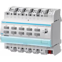
Marque : HAGER
Modèle : TYA610D
Catégorie : Chargeur électrique