041A3504-1 - Porte de garage LiftMaster - Notice d'utilisation et mode d'emploi gratuit
Retrouvez gratuitement la notice de l'appareil 041A3504-1 LiftMaster au format PDF.


| Type de produit | Télécommande pour porte de garage |
| Marque | LiftMaster |
| Modèle | 041A3504-1 |
| Nombre de boutons | 3 (ouverture, fermeture, arrêt) |
| Alimentation | Pile CR2032 (3V) |
| Portée maximale | Jusqu'à 100 mètres en champ libre |
| Fréquence de fonctionnement | 315 MHz |
| Technologie de sécurité | Code tournant Security+ 2.0 |
| Compatibilité | Portes de garage LiftMaster, Chamberlain, et autres marques compatibles |
| Fonctions principales | Ouverture, fermeture, arrêt, verrouillage |
| Indicateur LED | Oui, confirme la transmission |
| Dimensions | 5 x 3 x 1 cm environ |
| Poids (avec pile) | 20 g environ |
| Température de fonctionnement | -20°C à 50°C |
| Matériau | Plastique ABS |
| Installation | Aucune installation requise, programmation simple |
| Entretien et nettoyage | Nettoyer avec un chiffon doux et sec. Éviter l'humidité. |
| Sécurité | Code tournant empêchant les interceptions |
| Pièces détachées et réparabilité | Pile CR2032 disponible séparément. Non réparable, remplacer si défectueux. |
| Garantie | 1 an |
| Informations générales | Conforme aux normes FCC et CE |
FOIRE AUX QUESTIONS - 041A3504-1 LiftMaster
Questions des utilisateurs sur 041A3504-1 LiftMaster
0 question sur cet appareil. Repondez a celles que vous connaissez ou posez la votre.
Poser une nouvelle question sur cet appareil
Téléchargez la notice de votre Porte de garage au format PDF gratuitement ! Retrouvez votre notice 041A3504-1 - LiftMaster et reprennez votre appareil électronique en main. Sur cette page sont publiés tous les documents nécessaires à l'utilisation de votre appareil 041A3504-1 de la marque LiftMaster.
MODE D'EMPLOI 041A3504-1 LiftMaster
The Antenna Extension Kit model 41A3504-1 was designed to work with the 433MHz Receiver Logic Boards.
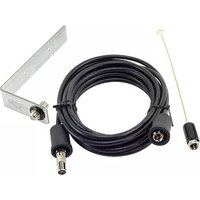
This kit contains an antenna, coaxial cable, adapter and an antenna bracket.
After replacing your receiver panel, follow the instructions below to access the logic board connector and install the antenna extension.
Installation
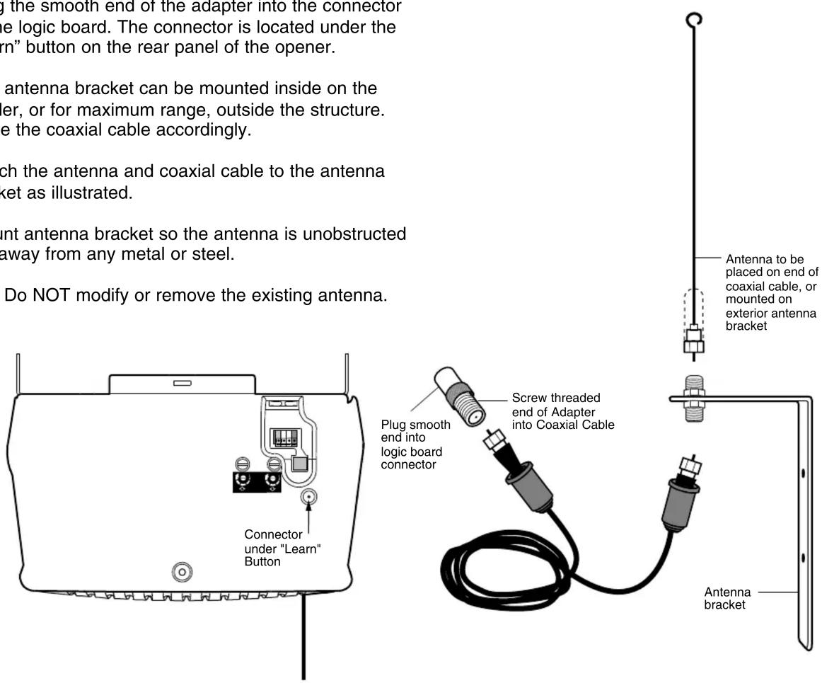
- Screw the threaded end of the adapter into either end of the coaxial cable.
- Plug the smooth end of the adapter into the connector on the logic board. The connector is located under the "Learn" button on the rear panel of the opener.
- The antenna bracket can be mounted inside on the header, or for maximum range, outside the structure. Route the coaxial cable accordingly.
- Attach the antenna and coaxial cable to the antenna bracket as illustrated.
- Mount antenna bracket so the antenna is unobstructed and away from any metal or steel.
NOTE: Do NOT modify or remove the existing antenna.
433MHz Receiver Logic Board Antenna Extension Kit
Model 41A3504-1

WARNING
To prevent possible SERIOUS INJURY or DEATH from electrocution, disconnect power to opener BEFORE proceeding

Marque : LiftMaster
Modèle : 041A3504-1
Catégorie : Porte de garage