
MBQR-STG5-RC1 - Autoradio MB QUART - Notice d'utilisation et mode d'emploi gratuit
Retrouvez gratuitement la notice de l'appareil MBQR-STG5-RC1 MB QUART au format PDF.


| Type de produit | Autoradio |
| Marque | MB Quart |
| Modèle | MBQR-STG5-RC1 |
| Dimensions (H x L x P) | 50 x 180 x 160 mm |
| Poids | 0,5 kg |
| Alimentation | 12 V CC (batterie véhicule, négatif à la masse) |
| Consommation électrique | Max. 10 A |
| Puissance de sortie | 4 x 50 W max (crête) |
| Type de tuner | FM/AM stéréo |
| Réception radio | FM 87,5 – 108 MHz, AM 530 – 1710 kHz |
| Entrées audio | AUX 3,5 mm (face avant), USB (face avant) |
| Lecture audio | MP3, WMA, WAV via USB |
| Connectivité | Bluetooth pour appels mains-libres et streaming audio |
| Affichage | LCD rétroéclairé |
| Fonctionnalités | RDS, horloge, égaliseur préréglé |
| Télécommande | Incluse (filaire ou infrarouge selon version) |
| Sécurité | Face avant amovible (détachable) |
| Entretien et nettoyage | Nettoyer avec un chiffon doux et sec. Ne pas utiliser de produits chimiques ou abrasifs. |
| Pièces détachées | Face avant, télécommande, câbles (disponibles auprès du fabricant) |
| Réparabilité | Contacter un technicien agréé pour toute réparation. |
| Informations générales | Notice d'utilisation complète disponible en PDF sur notice-facile.com |
FOIRE AUX QUESTIONS - MBQR-STG5-RC1 MB QUART
Questions des utilisateurs sur MBQR-STG5-RC1 MB QUART
0 question sur cet appareil. Repondez a celles que vous connaissez ou posez la votre.
Poser une nouvelle question sur cet appareil
Téléchargez la notice de votre Autoradio au format PDF gratuitement ! Retrouvez votre notice MBQR-STG5-RC1 - MB QUART et reprennez votre appareil électronique en main. Sur cette page sont publiés tous les documents nécessaires à l'utilisation de votre appareil MBQR-STG5-RC1 de la marque MB QUART.
MODE D'EMPLOI MBQR-STG5-RC1 MB QUART
MBQUARTI® MUSIC. DEFINED.
Installation Manual

natural_image
Product display of MBQUART audio/video equipment including speaker, fan, and control panel (no visible text or symbols)MBQR-STG5-2 MBQR-STG5-RC1
STAGE 5 800 WATT / FIVE SPEAKER RZR-Tuned Audio Package for Polaris® RZR® Vehicles
Thanks for choosing MB QUART! The RZR-Tuned Stage 5 Audio System Kit has been meticulously engineered for your vehicle. The process of installation is simple and straightforward. Installation following these detailed instructions can be completed in about 3.5 hours.

Many of the MB Quart vehicle-specific products feature a "how to" install video with additional details on a successful installation
Locate your specific video on the website. Type your model number (MBQR-STG5-2 or MBQR-STG5-RC1) into the search box, then click on the INSTALL & SUPPORT tab.
WHAT'S INCLUDED
The RZR ^® Stage 5 audio system ships in one box with everything you need for your application, either non-Ride Command ^® vehicles or those equipped with the Ride Command ^® system.
Non-Ride Command® Package (MBQR-STG5-2 Only)
- AM/FM/WB, Bluetooth, USB Source Unit with Vehicle-Specific Mounting Panel
- USB and 3.5mm Dash Mount Input Accessory (fits in switch knockout)
Ride Command® Package (MBQR-STG5-RC1 Only)
- 2 pcs. RC1-2RCA-F - Ride Command Audio System Interface Adapters
All RZR® Stage 5 System Packages (MBQR-STG5-2 or MBQR-STG5-RC1)
- Compact 2-channel, Class D 400 Watt Amplifier
- Compact Mono, Class D 400 Watt Subwoofer Amplifier
• Dual Amplifier Power and Speaker Harness - Two RCA Audio Patch Cables
- Dual Amplifier Vehicle-Specific Mounting Plates with Hardware
- Two Kick Panel-Mounted 8 inch Compression Horn Speakers in Vehicle-Specific Enclosures
- Two Roll Cage-Mounted 8 inch Compression Horn Speakers with Swivel-Mount Brackets
- Glove Box Replacement Vented Subwoofer Enclosure w/10" Subwoofer
- Rear Speaker Extension Harness (intended for 4-Door RZR Models)
- Zip-ties for Securing Audio System Wiring to Vehicle Harnesses
NOTE – Hardware for mounting components and other installation-related items you will need are contained in the kit. Do not dispose of any packaging until you have completely installed your system and certain you have accounted for every piece. If something is missing, please contact Maxxsonics directly via email – support@maxxsonics.com.
WARRANTY
Your audio system is covered by a 1-year warranty from the date of the invoice. It is important to retain your sales receipt. Furthermore, it is crucial that you record and store a record of the serial numbers for each of the components that are included in your system. In the rare instance that a warranty claim is needed both proofs of purchase and serial numbers are required. Additional information on the back page.
TECHNICAL SUPPORT
For additional technical information, go to the "SUPPORT" tab at MBQUART.com. There you will find helpful, FAQ, TEQ Tips and you can contact Technical Support via email.
INSTALLATION TIME
About 3.5 hours are required to complete this installation.
TOOLS AND SUPPLIES NEEDED
• Wire Strippers and Crimpers
- Flush Cut Wire Cutters (for trimming zip-ties)
- Hand-Held Drill and 5/16" Drill Bit
- Ratchet
- 10mm Socket
• T25 Torx Driver
- Blue Painter's Tape and Marker Pen
- Small (Jeweler's) Screwdriver
- Bojo Tools (Pry Tools)
- Socket (preferably deep)
• 1/2" Open Box Wrench
• T40 Torx Driver
Depending on which vehicle-specific RZR-Tuned audio system you are installing, you may or may not need all of the tools listed below. You may also own more specialized tools to complete the installation. Please share the pictures of your installation on MB Quart social media channels to help others.
In addition to the tools listed, have music ready for the INITIAL TESTING step. MB Quart recommends:
- USB thumb drive with music pre-loaded
- Bluetooth device such as a smartphone with music or a music app

natural_image
Person working on a battery component with red arrows indicating direction (no text or symbols visible)SAFETY PRECAUTIONS
Safely prepare your machine for the installation before proceeding.
- Turn the ignition off and remove the key
- Remove the negative terminal of the battery (Figure 1-1)
- Use a packing blanket other soft material to protect your machine
- Safety Glasses - always wear eye protection

natural_image
Coiled black electrical cable with red and gray connectors, labeled as Figure 1-2 (no text on main subject)PREPARATION FOR INSTALLATION
Before dismantling your vehicle, we suggest you prepare all your components, enclosures and wiring harnesses. It increases efficiency to have everything ready when each component is installed.
STEP 1 - CONFIRMING POWER TO BUS BAR
(Applies to 2013-2018 RZR Models)
The Polaris RZR and the MB Quart RZR-Tuned Audio System upgrade requires a harness that connects the battery under the seat to the bus bar harness located under the hood.
The harness is shown in Figure 1-2. Check that your 2013-2018 machine has this harness installed. If not, you can purchase from your dealer or Polaris online. The part numbers are 2881551 or 2881646 depending on which specific RZR model you own. 2018.5 Turbo S and all 2019+ RZR models already contain a bus bar harness.
TWO RZR-TUNED STAGE 5 AUDIO SYSTEM OPTIONS!
Depending on whether or not your RZR ^® vehicle has the optional Ride Command ^® system, you should have selected the appropriate MB Quart Stage 5 audio system to suit your application.
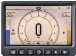
ABOUT RIDE COMMAND®
All Polaris® RZR® vehicles up to 2017 do not have the Ride Command. It wasn't available as an option. From the 2017 RZR XP® 1000 EPS Velocity Blue Limited Edition and later RZR model years, you can have Ride Command as an option.
VEHICLES WITH RIDE COMMAND®
If your 2017 or newer RZR model is equipped with the Ride Command system, the MBQR-STG5-RC1 is the correct Stage 5 audio system for your vehicle. This system does not include a source unit because you will retain the Ride Command system as the source unit. MB Quart provides two vehicle-specific Ride Command adapters in this kit to allow easy plug-in interface for connection to the amplifier inputs in the Stage 5 system. Throughout this installation manual, ensure the instructions you follow for installation applies to your Ride Command-equipped RZR vehicle.
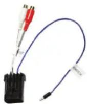
Ride Command Adapter
VEHICLES WITHOUT RIDE COMMAND®
If your RZR model is not equipped with the Ride Command system, the MBQR-STG5-2 is the correct Stage 5 audio system for your vehicle. This system includes the MBQR-RAD-2 digital media source unit in a vehicle-specific housing intended to fit in the storage pocket space at the center of the dash (once the pocket is removed). Throughout this installation manual, ensure the instructions you follow for installation applies to your non-Ride Command RZR vehicle.
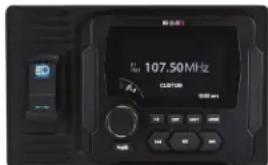
MBQR-RAD-2 digital media source unit
AUDIO SYSTEM ACCESSORIES FOR YOUR Polaris® RZR®
MB Quart offers audio system accessories to further personalize your vehicle. You can find more information at www.MBQuart.com.
SR1-120RGB LED RING LIGHT
The optional 8-inch SR1-120RGB LED ring light features 16 different colors, including 88 brightness variation of colors in between, and 4 effect modes including Flash, Strobe, Fade, and Smooth. Fits both the front kick panel speakers and the rear speaker pods included with the RZR Stage 5 audio system kits, with or without Ride Command®. Sold as pairs (2pcs).

natural_image
Simple red circular ring with glowing border (no text or symbols)SR1-120RGB LED Ring Light

natural_image
Black and white photo of a stylized lamp with a circular head and spoked wheels (no text or symbols visible)RFREM WIRELESS REMOTE
The optional MB RFREM wireless radio frequency (RF) remote for the MBQR-RAD-2 source unit is a Bluetooth device with 32ft. (10m) range. It's designed to mount on the inside of the RZR steering wheel and secured with a velcro strap. It has an IPX6 water-resistant rating. Does not work with Ride Command® system, only MBQR-RAD-2.

RFREM
Wireless Remote

natural_image
Close-up of a black and yellow handheld device with a keypad (no visible text or symbols)©2020 Maxxsonics USA, Inc.
DASH AREA DISASSEMBLY 2013-2018 (Non-Turbo S) RZR
Please note, separate disassembly instructions for the 2018.5 Turbo S and 2019+ RZR models are found on pages 7-9 in this manual.
STEP 1 – REMOVE CENTER HOOD
Start with removing the hood as shown in Figure 5-1. Twist the tabs at the upper left and right corners. Pull up to remove. This is where you will access the bus bar described on page 3 of this manual. Confirm that your machine has the bus bar harness installed. If your bus bar harness has not been installed, you can purchase from your dealer or Polaris online. The part numbers are 2881551 or 2881646 depending on which specific RZR model you own.

natural_image
Person in gloves handling an orange car body with a white patterned design, no visible text or symbols on the object itself.STEP 2 - REMOVE TOP OF DASH
Remove (2) T40 screws as shown in Figure 5-2. Slide dash forward to access back of dash and unplug gauges and switches one at a time. Set dash aside in a safe location.
STEP 3 – REMOVE THE GRAB BAR
Remove the grab bar as shown in Figure 5-3 by removing the retaining clip and pin and firmly pulling the grip toward the rear of the vehicle.

natural_image
Close-up of a person adjusting a black electronic device with visible wiring and components, labeled Figure 5-2 (no readable text or symbols)
natural_image
Person in blue shirt and black gloves handling a mechanical component, labeled 'Figure 5-3' (no other text or symbols visible)STEP 4 - REMOVING DASH POCKET & REAR MOUNT
To remove the DIN dash pocket from the dash, locate the rear support bracket at the rear of the pocket and remove the T40 Torx head screw as in Figure 5-4. Next, remove the clip shown on the right from the back and pull out the plastic pocket. Set aside the retaining clip shown in Figure 5-5 for re-use when mounting the MBQR-RAD-2 source unit.

Set aside OEM dash clip for source unit mounting later in the installation.

natural_image
Black plastic object with a curved handle and a hole, no visible text or symbolsFigure 5-5
DASH AREA DISASSEMBLY 2013-2018 (Non-Turbo S) RZR - Continued
STEP 5 – REMOVE DASH FASCIA CENTER HARDWARE
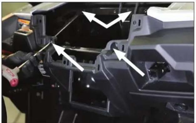
Remove (4) Torx screws from the front of the dash through the openings shown in Figure 5-6. The first set of Torx screws will come out allowing access to the second (upper) set further back in the dash. Next, pull the only the center of the dash loose as shown in Figure 5-7.
natural_image
Close-up of a mechanical assembly with white arrows indicating parts of a component (no visible text or symbols)
natural_image
Close-up of a gloved hand assembling a mechanical component, labeled Figure 5-7 (no text on the object itself)STEP 6 – REMOVE DASH FASCIA HARDWARE
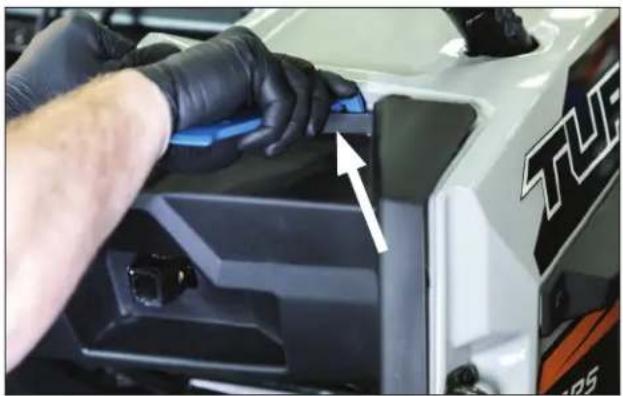
Using a large panel removal tool, release the side clips from the passenger's side front dash assembly as shown in Figures 5-8 and 5-9. Slowly ensure you account for all clips removed.
natural_image
Close-up of a person in gloves applying material to a white SUV engine compartment, with an arrow pointing to the component (no visible text or symbols)
natural_image
Close-up of a mechanical component with a white arrow pointing to a blue component, labeled Figure 5-9 and Figure 5-8 (no readable text or symbols on the component itself)STEP 7 – REMOVE THE GLOVE BOX
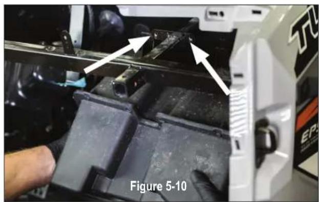
Remove (2) 10mm bolts on the top of the glove box where it is fastened to the grab bar framework. See holes in Figure 5-10. The glove box will easily slide out. A different mounting method is used for the new subwoofer.
Go to page 10 for next steps on these model year vehicles.
natural_image
Close-up of a mechanical component with arrows pointing to features, labeled as Figure 5-10 (no readable text or symbols beyond label)DASH AREA DISASSEMBLY 2018.5 Turbo S & 2019+ RZR (RIDE COMMAND)
Please note, separate disassembly instructions for the 2013-2018 RZR models are found on pages 5-6 in this manual.
STEP 1 – REMOVE CENTER HOOD
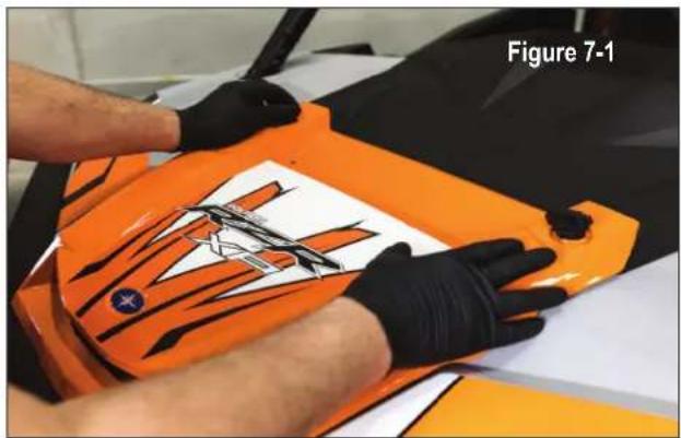
Remove the center of the hood area as shown in Figure 7-1. Twist the recessed tabs at the upper left and right corners. Pull up to remove. Next, pull passenger's side grab bar retaining clip and pin, then firmly pulling the grip toward the rear of the vehicle.
natural_image
Person in gloves handling an orange car body with a white patterned design (no visible text or symbols)STEP 2 - REMOVE CENTER SHROUD
Remove (2) plastic push clips behind the center shroud as shown in Figure 7-2a to remove the Ride Command cover or pocket depending on your vehicle. Cover removed shown in Figure 7.2b.

natural_image
Close-up of a red and black vehicle chassis with white arrows pointing to specific components (no text or symbols visible)
natural_image
Close-up of a red vehicle chassis with black plastic components and a white vent, no visible text or symbolsSTEP 3 - REMOVE FULL FRONT COVER DASH TOP ASSEMBLY
Remove (2) T40 screws located by the A-pillars as shown in Figure 7-3a. Next, remove the (2) T40 screws holding the front of the dash in the inner fender near the water bottle and bus bar. Lift upwards to release the top of the dash cover and remove as shown in Figure 7-3b.

natural_image
Close-up of a red robotic arm pressing a small mechanical component on a metal workbench, with an arrow pointing to the component (no text or symbols visible)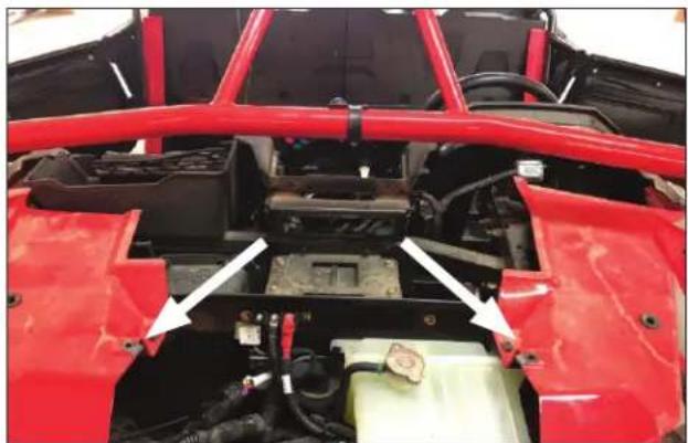
natural_image
Red vehicle chassis frame with visible structural components and white arrows indicating parts of the engine (no text or symbols)DASH AREA DISASSEMBLY 2018.5 Turbo S & 2019+ RZR - Continued
STEP 4 – REMOVE DYNAMIX® ECU BRACKET OR POCKET SCREW
If no Ride Command, Dynamix ECU or OEM installed amplifier are present, proceed to removing lower pocket. If you have the Dynamix ECU or OEM installed amplifier, remove (4) 10mm bolts holding the bracket as shown in Figure 7-4a. Move the ECU and/or OEM amplifier to the side leaving wire connections intact. Lower pocket removal is (1) T40 screw on the pocket support bracket as shown in Figure 7-4b.

natural_image
Close-up of a mechanical component with arrows pointing to features, labeled Figure 7-4a and Figure 7-4b (no readable text or symbols beyond labels)
STEP 5 – REMOVE LOWER POCKET AND PASSENGER SIDE CUBBY
Remove the lower pocket by pulling forward as shown in Figure 7-5a. If you have Ride Command you will also have to disconnect the USB cable. If you don't have Ride Command, the pocket area is where the MB Quart source unit installs. Next, remove (2) plastic push clips in the passenger side cubby as shown in Figure 7-5b. Then remove cubby and set aside.

natural_image
Interior view of a vehicle dashboard with control panel and buttons, no visible text or symbols on the main components.
natural_image
Close-up of a metal component with two white arrows pointing to a raised bolt, next to a red vehicle (no text or symbols visible)STEP 6 – REMOVE CENTER SWITCH HARDWARE
Remove (4) T40 screws located above the center switches as in Figure 7.6a. If you have a Ride Command, (2) will be on each side of the screen and (2) behind the screen as in Figure 7.6b.

natural_image
Front view of a black electronic device with a display screen and control buttons, labeled 'Figure 7-6a' (no readable text or symbols beyond labels)
natural_image
Close-up of a mechanical component with white arrows pointing to features, labeled as Figure 7-6b (no readable text or symbols beyond label)DASH AREA DISASSEMBLY 2018.5 Turbo S & 2019+ RZR - Continued
STEP 7 – PREPARE FINAL ELECTRONICS FOR DASH REMOVAL
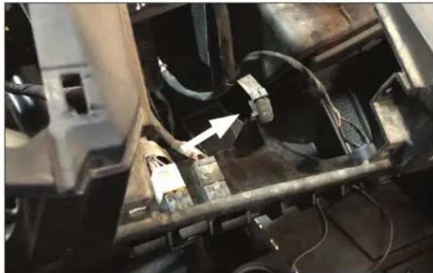
Gently remove the plastic nut holding the ignition switch to the dash as shown in Figure 7-7a. Next, disconnect wires from back of switches as shown in Figure 7-7b. Take note of plug color and switch location for reassembly purposes.

natural_image
Close-up of a vehicle's internal components with visible wiring and a white arrow pointing to a component (no text or symbols)STEP 8- REMOVE DASH FASCIA
Gently pull dash fascia toward seat to remove as shown in Figure 7-8. Set aside in a safe location until it's time for reassembly.

natural_image
Interior view of a red vehicle chassis frame with visible motors, dashboard, and steering wheel (no text or symbols)STEP 9 – REMOVE THE GLOVE BOX
Remove (2) 10mm bolts on the top of the glove box where it is fastened to the grab bar framework. See holes in Figure 7-9. The glove box will easily slide out. A different mounting method is used for the new subwoofer.

natural_image
Close-up of a mechanical device with labeled components and arrows indicating movement, no readable text or symbols present.Go to page 10 for next steps on all model year RZR vehicles.
REMOVE SEATS AND CENTER CONSOLE (ALL MODELS)
STEP 1 – REMOVE SEATS
Remove driver and passenger seats by pulling on the lock clip shown in Figure 8-1a. This lock clip is located between the bottom and upright portion of the seat.
Behind the seats in the center of the machine is the panel where you access the oil filter. You will need to remove this as shown in Figure 8-1b in order to feed and secure the rear speaker harness if not routing the rear speaker harness inside the body panels.

natural_image
Interior view of a car seat with black and orange patterned seating, showing a person's arm and seatbelt (no text or symbols visible)
natural_image
Close-up of a mechanical component with a rectangular opening and two red-lit ports, no visible text or symbols.STEP 2 - UNBOLT AND MARK CENTER CONSOLE HARDWARE
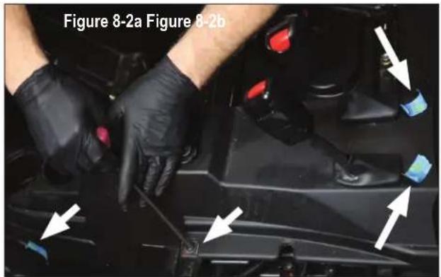
Use the painters tape to mark where you remove each of the push pins and/or T40 screws in the seat side and seatbelt area as shown in Figure 8-2a. Remove and mark the final T40 screw at the front of the console. We recommend using small disposable cups or sealable sandwich bags to label the different screws in order to keep track of them for reassembly.

natural_image
Close-up of a car interior showing hand positioning and control panel (no visible text or symbols)STEP 3 - REMOVE CENTER CONSOLE
Gently push the shifter and seat belt boots back through the console as shown in Figure 8-3. Carefully remove the center console from the vehicle. Set aside in a safe location until it's time for reassembly.

INSTALL POWER HARNESS AT BUS BAR (ALL MODELS)
You must prepare the power portion of the audio harness and run into the vehicle before wiring and connecting any of the audio system components.
STEP 1 - REMOVE RZR BUS BAR FACTORY CONNECTIONS
Remove the connections to the RZR bus bar as shown in Figure 9-1 to allow connecting the audio harness along with reconnecting the RZR bus bar harness.
STEP 2 - LAY IN HARNESS - IDENTIFY FIREWALL GROMMET
Beginning at the RZR bus bar, route the power, ground, and accessory portion of the audio system harness in the front vehicle. The harness will run through the grommet next to an existing wiring harness as shown in Figure 9-2. Do not use other grommets if present, empty or not. Use only the grommet shown.


natural_image
Close-up of a car battery terminal with visible wiring and components, labeled Figure 9-2 (no readable text or symbols beyond label)STEP 3 - CUT OPENING IN GROMMET AND RUN WIRING THROUGH
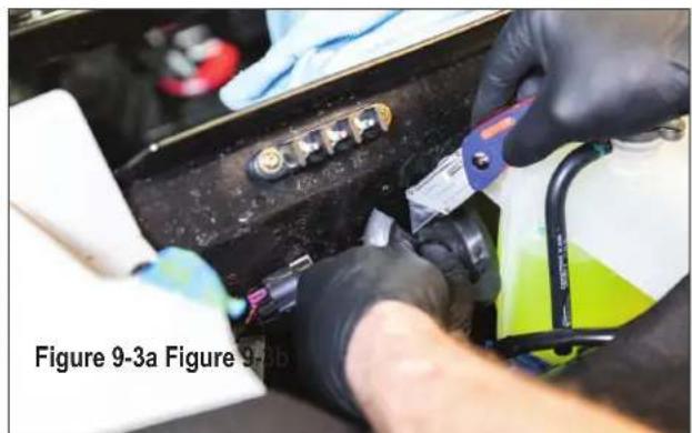
Using a razor knife, carefully slice the rubber grommet on the top side as shown in Figure 9-3a. This allows you to move the harnesses into the dash and to the amplifiers. Push the radio, rear speaker/illumination, and amplifier connections through the grommet as in Figure 9-3b. Leave accessible from the inside of the vehicle. Use black electrical tape or silicone-based caulking to seal the slice during the final inspection.
natural_image
Close-up of hands installing or adjusting a mechanical component with a blue tool (no visible text or symbols)
natural_image
Close-up of gloved hands installing or adjusting a black electrical component with colored wires (no visible text or symbols)STEP 4 - COMPLETE BUS BAR CONNECTION
Complete connections at the bus bar as shown in Figure 9-4. Mount the MB Quart audio harness first, with the OEM RZR connections on top. This allows you to use the red boot on the powerline, keeping your install clean and looking factory installed. Zip-tie this power portion of the harness into place. Assure that no added wiring is near any moving parts or components that generate large amounts of heat.

natural_image
Close-up of a gloved hand installing or adjusting components on a car battery panel (no visible text or symbols)AMPLIFIER PREPARATION AND MOUNTING (2013-2018 Models)
Before installing the dual amplifier plate with the amplifier(s) in position, you must prepare the mounting area in the vehicle to accept the plate.
NOTE - These instructions assume both amplifiers and all speakers are present in a full Stage 5 System. If not all components are present in your system, this makes upgrading much easier.
STEP 1 - LOOSEN STEERING COLUMN NUTS
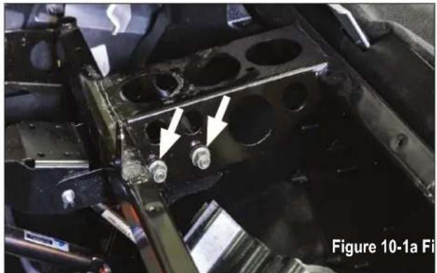
Loosen the 16mm nuts that secure the steering column to the support frame shown in Figure 10-1a. These nuts are very hard to loosen. Be careful. Do not remove these steering column nuts, only loosen to create an 1/8 inch gap between the nut and the frame shown in Figure 10-1b. You will not re-tighten these nuts until the installation of the whole system is finalized, tested and the vehicle is ready for reassembly.
natural_image
Close-up of a mechanical component with circular holes and two white arrows pointing to features, labeled as Figure 10-1a (no readable text or symbols beyond label)
STEP 2 - AMPLIFIER MOUNTING
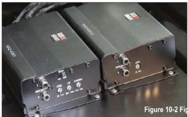
Mount your amplifier(s) on the dual amplifier plate as shown in Figure 10-2 (below). This configuration is critical to make sure you can access your fine-tune adjustments for crossover and bass boost.
STEP 3 - MOUNTING PLATE INSTALLATION
With the amplifiers mounted to the plate, slide it into position with the double groove portion of the bracket sliding between the steering column support shown in 10.1b (above) and the 16mm nuts and washers. Do not tighten down yet. On the front edge, you will secure the plate with the 10mm bolt you removed from the dash pocket which will also hold the bracket then will ultimately support the new dash pocket with the source unit. The finished plate should look like Figure 10-3.
natural_image
Two black industrial electronic devices labeled N2-1021 and N2-1022, with control knobs and indicator lights (no visible text or symbols on the devices themselves)
natural_image
Two black electronic devices mounted on a vehicle chassis, with one device showing a 10mm scale indicator (no visible text or symbols on the devices themselves)You will tighten the 16mm nuts and washers next to the steering column once reassembly of the vehicle begins. This allows easy removal of the amplifier plate for troubleshooting (if necessary).
NOTE - The dual amplifier harness is designed and laid out to perfectly connect power and speaker connections on the driver's side of the amplifiers while the RCA audio connections are on the passenger side of the RZR.
AMPLIFIER PREPARATION AND MOUNTING (2018.5 Turbo S & 2019+ Models)
Before installing the dual amplifier plate with the amplifier(s) in position, you must prepare the mounting area in the vehicle to accept the plate. The amplifier plate is installed centered, up high under the dash. Use the information in this section to determine which installation steps are specific to your vehicle and options.
NOTE - These instructions assume both amplifiers and all speakers are present in a full Stage 5 system. If not all components are present in your system, this makes upgrading much easier.
STEP 1 – DETERMINE YOUR MODEL'S OPTIONS FOR DUAL AMPLIFIER PLATE MOUNTING
Factory-Installed (OEM) Amplifier ONLY
- If you have ONLY the OEM installed amplifier and are re-using it, you must remove it from the top of the factory plate and reinstall on the bottom side of the plate to allow clearance for the other amplifier plate. If you are NOT re-using the OEM amplifier you can disconnect the amplifier and remove the amplifier and mounting plate. You will still reuse (2) 10mm bolts to secure the dual amplifier plate with this kit.
Dynamix® ECU ONLY
- If you have ONLY the Dynamix ECU then set the ECU and ECU mounting bracket back in the original placement ensuring the wiring intended for the amplifier harness is routed through the gap area at the forward section of the bracket. Loosely reattach only the two (2) 10mm rear bolts for the ECU bracket (nearest the dashboard) as shown in Figure 10-4. *It is only important the ECU bracket is back in place for trial fitting of the dual amplifier plate. It will not have its final reassembly at this step.

Factory-Installed (OEM) Amplifier AND Dynamix® ECU
- If you have the Dynamix ECU AND the OEM installed amplifier and planning on re-using the OEM amplifier, then the OEM amplifier will need to be relocated elsewhere to make room for the amplifier plate provided in this kit. If you are NOT re-using the OEM amplifier you can disconnect the amplifier and remove it. Loosely reattach only the two (2) 10mm rear bolts for the ECU bracket (nearest the dashboard) as shown in Figure 10-4. *It is only important the ECU bracket is back in place for trial fitting of the dual amplifier plate. It will not have its final reassembly at this step.
NO Factory-Installed (OEM) Amplifier OR Dynamix® ECU
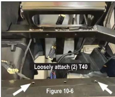
- If you have NO Dynamix ECU or OEM installed amplifier, use the (2) T40 screws provided in the MB Quart RZR Stage 5 kit as shown in Figure 10-5. These screws attach the amplifier plate in the two identified holes as shown in Figure 10-6.

Figure 10-5
T40 Screws
AMPLIFIER PREPARATION AND MOUNTING (2018.5 Turbo S & 2019+ Models Continued)
STEP 2 - AMPLIFIER MOUNTING
Mount the MB Quart amplifier(s) on the dual amplifier plate in the configuration shown in Figure 10.7. This configuration is critical to make sure you can access your fine-tune adjustments for level, low pass filter (LPF) and bass boost.

natural_image
Two black industrial electronic devices labeled 'NAC-400.2' and 'FOOD-CAN', with no visible text or symbols on the devices themselves.STEP 3 – TRIAL FITTING THE DUAL AMP PLATE
With the amplifier(s) mounted to the plate, place it into position as shown in Figure 10-8. Be sure there is free movement of the wiring harness with enough length to connect to the amplifier's onboard connectors.
- if you have the Dynamix ^ ECU and/or OEM amplifier bracket - Loosely fit the remaining two (2) 10mm bolts to check the fit of the dual amp plate. This is shown in Figure 10-8.
- If NO Dynamix ^ ECU or OEM amplifier bracket
- Use the two (2) T40 screws provided with the MB Quart Stage 5 kit to check the fit of the dual amp plate.

Connect the power and speaker wiring to the harness as labeled. Do not zip-tie anything at this point as the dual
amp plate will not have its final reassembly until after the system has completed the steps in the INITIAL TESTING and FINE TUNING sections.
STEP 4 – REMOVE DUAL AMP PLATE FROM ITS LOCATION AND FLIP OVER
With the amplifiers connected to the wiring harness, place a towel or blanket over the open hood area.
- If you have the Dynamix ^ ECU and/or OEM amplifier bracket - Remove the first two (2) 10mm bolts. Remove the dual amp plate and flip it over on a towel or blanket to avoid scratching the amplifier(s) heatsink as shown in Figure 10-9. Next, remove the remaining two (2) 10mm bolts from the ECU or OEM amplifier mount (if present) and place the ECU to the side as when initially disassembled on page 8.
- If NO Dynamix ^ ECU or OEM amplifier bracket - Remove the (2) T40 metal screws for the amp plate. Remove the dual amp plate and flip it over on a towel or blanket to avoid scratching the amplifier(s) heatsink as shown in Figure 10-9.
This step will allow you to continue working on the other parts of the installation and access other wiring until you're ready to power up the system, complete final testing and finalize the reassembly.

natural_image
Close-up of a black electronic device with wiring and connectors, placed on a textured surface (no visible text or symbols)SUBWOOFER ENCLOSURE MOUNTING (ALL MODELS)
Prepare to mount the subwoofer into the glove box and grab bar location. 2018.5 Turbo S and 2019 and newer RZR models, use only the rear mounting plate and four 1/2" bolts as shown in Figure 11-1. All other RZR models use both mounting plates and all eight 1/2" bolts as shown in Figure 11-2.
2018.5 Turbo S and 2019+ RZR Models use only rear mounting plate and four 1/2" bolts.

natural_image
Close-up of a black electronic device with three metallic pins and a central connector (no visible text or symbols)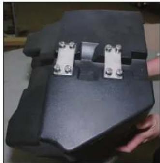
natural_image
Close-up of a black plastic enclosure with two metallic connectors, held by a hand (no visible text or symbols)2013-2018 (non Turbo) RZR Models use both mounting plates and eight 1/2" bolts.
STEP 1 – POSITION SUBWOOFER ENCLOSURE
Sitting on the floor of the RZR, hold the subwoofer enclosure up to the grab bar pipe and push it forward into place as shown in Figure 11-3.
STEP 2 – BEGIN MOUNTING ENCLOSURE
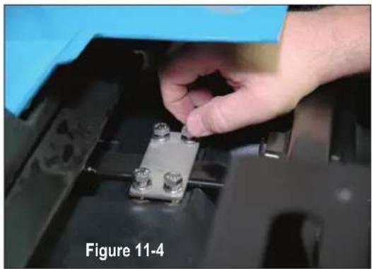
Begin mounting the subwoofer to the RZR using the supplied steel plates and bolts as indicated for your specific year and model. Start by hand-threading the bolts until finger tight as indicated in Figure 11-4, Then, use a 1/2 inch socket with a small ratchet to begin tightening the bolts. Space is tight for any larger tools, a smaller ratchet will work best.
NOTE – Ensure the wiring harness from the subwoofer does not get pinched behind the enclosure. This will prevent the enclosure from seating properly and will not allow the front dash to snap into place properly. The harness should be routed over the top of the push bar frame to the subwoofer amplifier connector.
STEP 3 - FINISH SUBWOOFER MOUNTING
Tighten a few threads at a time on each bolt to allow the subwoofer to rise up against the pull bar frame evenly. This will allow the subwoofer to seat properly against the frame of the vehicle. Torque the bolts to 5.65 N.m (0.576 Kgf.m / 50lbs in), over tighening will cause the enclosure to crack and will not be covered under warranty.
NOTE – When the subwoofer starts to seat into place, continue to push the subwoofer firmly forward as shown in Figure 11-3 as you tighten mounting hardware. This forward pressure will be critical when you reassemble the front dash for fitment into all the clips.
STEP 4 - ROUTE SUBWOOFER WIRING HARNESS
Route the subwoofer enclosure's wiring harness over to the amplifier area. Connect it to the speaker output of the mono amplifier as shown in figure 11-5.
The next section describes connecting the other wiring harnesses to the amplifiers.

natural_image
Close-up of a hand installing or adjusting a metal component on a black vehicle chassis (no visible text or symbols)
AMPLIFIER AND SPEAKER WIRING HARNESS CONNECTIONS
With your amplifier(s) mounted, subwoofer installed and connected to the mono amplifier, you can now begin laying in the front/rear speaker harnesses and plugging in all the remaining connectors. While you are working on your system, we recommend covering the amplifiers to avoid scratching them or inadvertently hitting the adjustment dials with a wrench or screw driver.
STEP 1 – POWER AND SPEAKER CONNECTORS AT AMPLIFIERS
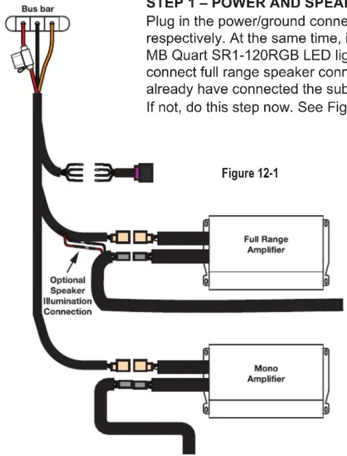
Plug in the power/ground connector of the two channel and the mono amplifiers respectively. At the same time, if you have (or will later install) optional illuminated MB Quart SR1-120RGB LED light rings, connect the red/black wires as well. Next, connect full range speaker connectors to the two channel amplifier. You should already have connected the subwoofer to the mono amplifier in the previous section. If not, do this step now. See Figure 12-1 for the connection diagram.
STEP 2 – ROUTE FRONT SPEAKER HARNESS
Make sure your front left and front right kick panel harnesses are set into place.
The left front harness for the kick panel should be routed down the left side of the steering column to the kick panel area.
The right front harness for the kick panel needs to be routed over the subwoofer, not behind, and then to the kick panel area.
The kick panel pod installation will take place at a later step. For now, you are simply pre-wiring the harnesses to their respective areas.
STEP 3 - ROUTE REAR SPEAKER HARNESS
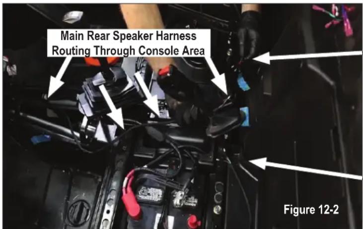
Route rear speaker harness toward rear speakers through the console area as shown in Figure 12-2. You can route the remaining harnesses to the rear pod area by either removing the oil filter cover on the back wall or route your wires through small gaps in the body panels.
NOTE – On a four seat RZR (4P RZR) you will need to include the 4P jumper to extend the rear speaker harness, past the rear seats and then to the rear pod area. See Figure 12-3 for connection.

REAR SPEAKER POD INSTALLATION
Every roll cage angle is a bit different; therefore you should take the time to install the swivel mount brackets on the roll cage to ensure a good fit.
These brackets are designed to allow 180 degree tilt. This ensures that the speaker points directly forward. This flexibility in positioning improves sound quality and overall volume. Note the location of the Adjustment Locking Screw is at the rear of the assembly as shown in Figure 13-1.
STEP 1 - MOUNT SPEAKER PODS w/BRACKETS
Stock RZR roll cages use the 1.75 inch tube. If you have an aftermarket or custom cage you will find the correct bushings and mounts included in the box with the pods. Refer to the manual included with your pods for additional details on mounting and wiring.

Mount the pod and swivel bracket to the roll cage tube. Once the speakers are on the roll cage tube, you can gently slide the pod up or down on the tube to determine where your final height will be. Use painter's tape to measure and mark a general position so it's even on both sides. Figures 13-2a and 13-2b show potential mounting options to try out.

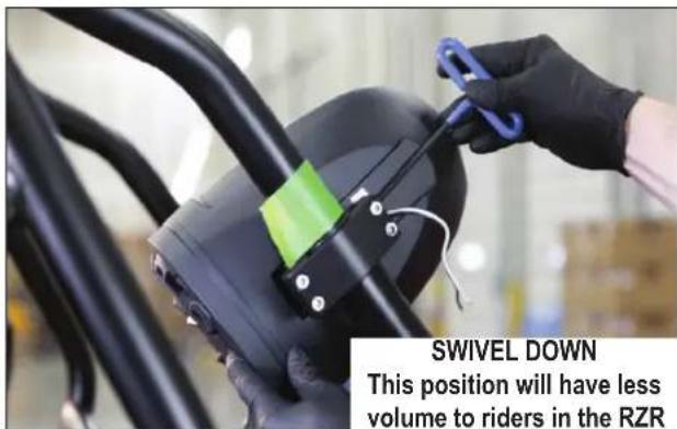
Once the general mounting position is chosen, do not fully tighten the pods as you may want to do final adjustments for your ear height after the seat is in position and the system is playing music.
STEP 2 - CONNECT WIRING
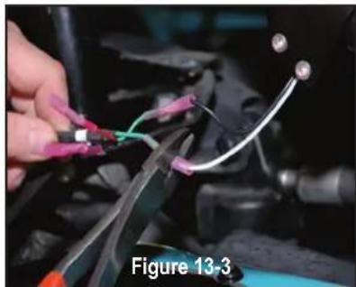
Make two (2) crimped speaker wiring connections as indicated in Figure 13-3 for the driver's side pod. Illumination wiring is optional with accessory rings. Repeat the two (2) wiring connections for the passenger's side pod.
natural_image
Close-up of hands connecting automotive wires to a black vehicle, labeled as Figure 13-3 (no text on wires or background)• SOLID GREEN - Left Rear Speaker + (White Wire)
• GREEN/BLACK - Left Rear Speaker - (Black Wire)
• SOLID PURPLE - Right Rear Speaker + (White Wire)
• PURPLE/BLACK - Right Rear Speaker - (Black Wire)
- RED - Illumination + (Optional LED Light Ring Required)
- BLACK - Illumination -

natural_image
Close-up of a hand holding a small electronic component with a lit flame, connected to wires (no visible text or symbols)STEP 3 - HEAT SHRINK WIRING CONNECTIONS
Use a lighter or heat gun to heat shrink and seal the crimped connections as shown in Figure 13-4 to ensure no moisture penetration.
Note: Do not zip-tie the wires along the roll cage or gather up excess wire until the system has been fully tested.
MOUNTING THE KICK PANEL SPEAKERS
Through hundreds of installations, we've found once mounting holes are drilled, it's best to start with the driver's side kick panel and then move on to the passenger's side kick panel to complete the mounting and wiring of the kick panels. This way you only need the drill out once, then completely finish the left before moving on to the right. The subwoofer should already be mounted at this stage and both kick panel wires run to their respective general areas.
STEP 1 - MARK HOLES USING SUPPLIED TEMPLATE
Use a few small lengths of painter's tape in the kick panel area to easily see marks left by a felt-tipped pen or pencil. Place the clear plastic template on driver's side as shown in Figure 14-1 and mark the mounting holes to drill. Repeat on the passenger side.
STEP 2 - DRILL HOLES
Drill (2) 1/2 inch mounting holes into the fender where you marked the tape shown in Figure 14-2. A 1/2 inch step drill bit is recommended for this step. Repeat this process and drill two more 1/2 inch mounting holes on the passenger's side kick panel area. Remove any tape in the drilling area from the interior kick panels.
STEP 3 - PLACE DRIVER'S SIDE KICK PANEL
Place driver's side kick panel pod in its location as shown in Figure 14-3. Ensure the positioning lines up with the holes you've drilled.
STEP 4 – PUSH OUTER BOLTS THROUGH FENDER AND MOUNT DRIVER'S SIDE KICK PANEL
With the included hardware push (1) bolt and (1) washer through the driver's side inner fender well into the threaded insert of the driver's side kick panel pod. This leaves only the head of the bolt visible behind the tire.
Once the first bolt and washer are threaded in, insert and thread the second bolt and washer for a total of two bolts/washers attaching the kick panel pod to the driver's side fender well as shown in Figure 14-4.
NOTE - Wait to mount passenger side kick panel until driver's side panel is completely mounted and wired.
STEP 5 – CONNECT WIRE HARNESS INTO KICK PANEL
Connect the wire harness from the amplifier that you routed earlier to the wire harness from the kick panel.

natural_image
Person cleaning a car interior with a transparent plastic bag, labeled as Figure 14-1 (no text on bag or background)
natural_image
Close-up of a hand using a power drill to work on a blue plastic component, labeled as Figure 14-2 (no text or symbols on the diagram itself)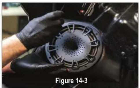
natural_image
Close-up of a gloved hand holding a mechanical component with perforated circular opening (no text or symbols visible)
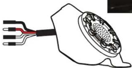
• SOLID WHITE - Left Front Speaker +
- WHITE/BLACK - Left Front Speaker -
- RED - Illumination + (Optional LED Light Ring Required)
- BLACK - Illumination -
(Continued on next page)
natural_image
Diagram of a connector with wires and a mesh head (no text or symbols)MOUNTING THE KICK PANEL SPEAKERS (Continued)
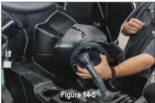
STEP 6 – PLACE PASSENGER SIDE KICK PANEL
Place passenger side kick panel pod in its location as shown in Figure 14-5. Ensure the positioning lines up with the holes you've drilled.
STEP 7 – PUSH OUTER BOLTS THROUGH FENDER AND MOUNT DRIVER'S SIDE KICK PANEL
With the included hardware push (1) bolt and (1) washer through the inner passenger side fender well into the threaded insert of the driver's side kick panel pod. This leaves only the head of the bolt visible behind the tire.
Once the first bolt and washer are threaded in, insert and thread the second bolt and washer for a total of two bolts/washers attaching the kick panel pod to the passenger side fender well as shown in Figure 14-6.
NOTE - Make sure that the wires behind the subwoofer enclosure on the passenger side remain accessible for connecting to the amplifier harness. Use some painters tape to keep them from getting blocked by the enclosure if necessary.
natural_image
Person adjusting a black mechanical component with a lever, labeled 'Figure 14-5' (no other text or symbols visible)
STEP 8 - CONNECT WIRE HARNESS INTO KICK PANEL
Connect the wire harness from the amplifier that you routed earlier to the wire harness from the passenger side kick panel.
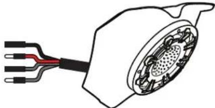
• SOLID GRAY - Right Front Speaker +
• GRAY/BLACK - Right Front Speaker -
- RED - Illumination + (Optional Optional LED Light Ring Required)
- BLACK - Illumination -
natural_image
Diagram of a mechanical component with internal gear and wires (no text or symbols)AMPLIFIER SETTINGS
Before preparing the source unit and dash reassembly, make the following adjustments to the setting. See the INITIAL TESTING and FINE TUNING sections for additional information on final system adjustments and personalized settings. The chart below provides general crossover and bass boost switch settings depending on the RZR tuned package you have.
TUNED PACKAGE TWO-CHANNEL AMPLIFIER MONO AMPLIFIER
| MBQR-STG5-2MBQR-STG5-RC-1 | ONLY LEVEL SETTING NEEDED | Bass Boost to 0dBLPF to 100Hz |
| MBQR-STG3-2MBQR-STG3-RC-1 | ONLY LEVEL SETTING NEEDED | Bass Boost to 0dBLPF to 100Hz |
| MBQR-STG2-RAD-2MBQ-STG2-BTMBQR-STG2-RC-1 | ONLY LEVEL SETTING NEEDED | N/A |
| MBQR-SUB-2 N/A Bass Boost to 0dB | LPF to 100Hz | |
This manual assumes the full Stage 5 System and provides the information for initial settings accordingly.
STEP 1 – ADJUST TWO-CHANNEL AMPLIFIER
Looking at the NA2-400.2RC shown in Figure 15.1, make the following initial adjustments:
- LEVEL - Rotate control to slightly past halfway (about the 1 o'clock position). This represents an input level that will closely match the source unit's output at full volume allowing the amplifier to achieve full power without notable distortion.
Figure 15-1

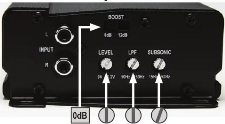
STEP 2 - ADJUST MONO AMPLIFIER
Looking at the NA2-400.1 shown in Figure 15.2, make the following initial adjustments:
- BOOST - Switch to "0dB" position.
- LEVEL - Rotate control to halfway (pointing up). This represents an input level that will closely match the source unit's output at full volume allowing the amplifier to achieve full power without notable distortion.
- LPF - Rotate control to halfway (pointing up). This is approximately 100HZ.
- SUBSONIC - Leave in the lowest (15Hz position). If the subwoofer has trouble with the lowest notes in your choice of music upon testing, you can adjust up slightly about 1/4 turn.
Figure 15-2
CONNECT RIDE COMMAND AUDIO ADAPTERS (Ride Command Models Only)
With the Ride Command STAGE Tuned Audio packages, two plug-in audio output adapters are included. These allow the vehicle's Ride Command system to easily connect to the system amplifiers while retaining Ride Command's functionality and features.
STEP 1 - LOCATE AUDIO OUTPUT PLUGS
There are three AMP plugs located behind and on either side of the Ride Command dash unit as shown in figure 20-1 and 20-2.
Identify the labels on the plugs. You are looking for "AMP1" and "AMP3" plug labels.
STEP 2 - CONNECT ADAPTERS
Connect the Ride Command adapters to AMP1 and AMP3 plugs as shown in figure 20-3. Both adapters are identical, so it's only important you note which are plugged into AMP1 and AMP3 audio outputs.
STEP 3 - CONNECT REMOTE AMP TURN-ON
Route and connect AMP1 blue wire (remote amp turn on) from the adapter to the blue wire in audio system's four-wire source unit harness. Only the blue wire connects. The three remaining wires are not used in a Ride Command application. See Figure 20-4.
Remove bullet connector, tape up or otherwise insulate the blue wire from the AMP3 adapter as this is not used. This will protect from short circuits.
STEP 4 - CONNECT RCAs TO AMPLIFIERS
Route and connect the RCA audio cables from the AMP3 adapter to the NA2-400.1 mono subwoofer amplifier. See Figure 20-4.
Route and connect the RCA audio cables from the AMP1 adapter to the NA2-400.2RC two-channel full range amplifier. See Figure 20-4.
Note about Ride Command fader operation - front and rear speakers in a MB Quart RZR-tuned Stage 5 system are on the "front" of the Ride Command outputs so there is no function for the "rear" on the fader once the system is installed and operating.

natural_image
Close-up of a hand adjusting a mechanical component with orange and black components (no visible text or symbols)
natural_image
Close-up of a hand adjusting a mechanical component with visible wiring and components (no text or symbols)
natural_image
Interior view of a vehicle chassis with visible wiring and components, labeled as Figure 20-3 (no readable text or symbols beyond label)
MOUNT THE USB & 3.5mm (AUX) DASH ADAPTER (Non-Ride Command)
With the non-Ride Command STAGE Tuned Audio packages, a PSAP-2S dual input waterproof dash adapter is included. This means that no matter how you store and play your music, you have plenty of connections.
STEP 1 - MOUNT ADAPTER
Route wires from the PSAP-2S input adapter through the switch opening in the vehicle-specific panel where the source unit is already mounted. Press the adapter into place to ensure the snaps lock it in.
STEP 2 - CONNECT TO SOURCE
There is an 18 inch (0.5 meter) cable that extends the USB and AUX input from your source unit. After mounting the adapter, run the cable to the source unit and connect the USB to the source unit connector and the 3.5mm RCA connectors to the source unit AUX-1 input.
After the INITIAL TESTING and FINE TUNING process is complete, zip tie and secure any excess cable length.

natural_image
Close-up of a black electronic device with a display and control panel, placed on a textured surface (no visible text or symbols)INSTALLING THE SOURCE UNIT (Non-Ride Command-Equipped)
Reassemble part of the front dash around the dash pocket area. Utilize the reverse method of how you removed the center section of the dash pocket. This will allow source unit installation for the non-Ride Command-equipped RZR vehicles. The harness can then be finished and connected in the proper location. Final fitting and reassembly of all panels is the last step of the installation after testing the system.
STEP 1 – RUN CONNECTIONS TO SOURCE UNIT AREA
Run the (2) RCA audio cables from the amplifier location into the area where the source unit will be installed. Be sure to observe left and right channels at the amplifier. Make note of which connects to the two-channel amplifier and which connects to the mono amplifier.

STEP 2 - MAKE SOURCE UNIT CONNECTIONS
With the harness routed through the vehicle and everything connected to the amplifier(s), make the final source unit electrical and RCA audio cable connections in the dash as shown in Figure 17-1.
First, connect the short Delphi connector with bullet connectors to the four-pin main power harness, matching color for color with the bullet connectors. Raise the completed source unit mount to the dash area. Connect the electrical (Delphi-style) connector as shown in Figure 17-2. Connect the front RCA preamp level outputs to the two-channel amplifier. Connect the sub RCA preamp level outputs to the mono amplifier.
NOTE – As you raise the completed source unit to the dash area, ensure you retained and installed the metal clip on the new source unit panel that was on the back of the original dash pocket.

STEP 3 - SECURE THE SOURCE UNIT
Push the dash assembly into place until as shown in figure Figure 17-3 until you feel and hear a snap as the entire assembly seats into place. Re-attach the metal clip with the T40 screw as shown in Figure 17-4.
Powering up the system and initial testing will be in a subsequent step.

natural_image
Close-up of hands installing or adjusting a car electrical panel with wires and components (no visible text or symbols)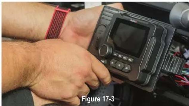
natural_image
Close-up of a person's wrist wearing a wristwatch and holding a digital device (no visible text or symbols)
INITIAL TESTING
This step is to confirm that everything is working before you put the vehicle back together.
STEP 1 – RECONNECT THE BATTERY
With the audio harness connected to the bus bar, you can now reconnect the negative terminal of the negative battery cable as indicated in Figure 19-1.
STEP 2 – TURN ON IGNITION
Turn the ignition key to the ACC position and push the PWR button on your source unit.
STEP 3a – INITIAL CHECKS (Non-Ride Command)
Confirm connectivity of the system you just installed. Refer to the full manual for the MBQR-RAD-2 source unit to use features like Bluetooth® pairing, adjusting treble and bass or working with the EQ. You will need to set the source unit's subwoofer low pass crossover and level in this step. With the power "ON" use the list here to check the system for all of the following:

natural_image
Interior view of a battery pack with visible wiring and a white arrow pointing to a component (no text or symbols)- POWER ON - MB Quart source unit lights up and responds to button presses
- USB INPUT (if used) responds when selected.
- AUX 3.5mm INPUT (if used) responds when selected.
- BT MUSIC - Follow the pairing instructions in your source unit and test a Bluetooth ^ source.
- AM/FM/WB RADIO - Unless you have installed an AM/FM antenna, you will only hear static.
- SUB FREQUENCY and LEVEL SETTING - In the settings menu, set the source unit's SUB OUT (Low Pass) crossover at 100Hz. Next, set the source unit's SUB OUT level at 35dB for the initial testing. A level setting of 35dB will allow the recommended gain control settings on the subwoofer amplifier to perform distortion-free, while also allowing you to fine-tune any bass-heavy music by easily reducing the sub-level setting from the source unit.
STEP 3b - INITIAL CHECKS (Ride Command-Equipped)
With the Ride Command unit power "ON", check the system for all of the following:
- POWER ON - Ride Command source unit lights up and responds to button presses.
- USB INPUT (if used) responds when selected on Ride Command unit.
- BT MUSIC - Follow the Ride Command pairing instructions and test a Bluetooth ^ source.
- AM/FM RADIO - If using AM/FM within Ride Command, check audio with a strong station.
Step 4 - SPEAKER AND AMPLIFIER CHECKS (all systems)
- CORRECT LEFT/RIGHT BALANCE - Make sure you are using the controls on the source unit to confirm "LEFT" is the left-side channel and "RIGHT" is the right-side channel. There will be no change on the fader front/rear speakers as all speakers are on the same two-channel (NA2-400.2RC) amplifier and "FRONT" output.
- AMPLIFIERS - If the speakers are playing, the amplifiers are on. Confirm settings are correct something doesn't sound exactly right. CONFIRM ALL SPEAKERS ARE CONNECTED TO THE CORRECT AMPLIFIER before making any further adjustments. Refer to page 24 for initial amplifier settings during the amplifier plate installation.
If everything is working and producing sound, proceed to the next section - Fine Tuning.
FINE TUNING
When setting up your amplifiers you will refer to the manual inside each amplifier. However, through hundreds of installations, we have determined the settings shown on page 20 are ideal for the STAGE Tuned Audio Packages.
NOTE – Gain control, it is important to adjust each amplifier gain as described in the manual. Remember, these settings are NOT volume controls. Gain controls, properly adjusted help properly balance the system sound between lows, highs and minimize distortion that comes from the source unit. Listen for a clear, crisp audio sound. The ideal gain setting should allow full volume from the source unit without audible distortion.

Settings
The illustrations below describe the various controls. Refer to the illustration that matches your amplifier.
Two Channel Amplifier
① GAIN Adjustment
The gain control purpose is to match the output of your source signal to the amplifier. Refer to the section B below for detailed instructions.
NA2-400.2RC

② LOW PASS Filter
The Low Pass Filter will cut off the frequencies above the setting.
③ SUBSONIC Adjustment
The Subsonic Filter will cut off the frequencies below the setting. If using with a subwoofer, the setting should be set between 15-25Hz.
Mono (Subwoofer) Amplifier

④ BOOST Switch
The Boost Switch will increase the signal 12dB at 45Hz. Be aware this setting can cause distortion if the gain is not set properly.

Level Setting

This is a critical step to insure your amplifier is properly adjusted to match the signal output level of your source unit.
THIS IS NOT A VOLUME CONTROL!
GAIN

MIN MAX
- If possible, with the source unit off, confirm that the primary volume control is turned down (counter clockwise).
- Turn on the source unit (CD, or MP3 player). Re-confirm that the volume is turned down. Make sure the source unit controls; balance, fader, bass and treble are all set to center or "0" adjustment. Make sure that the green LED on the end of the amplifier is illuminated.
- Play a clean musical selection of which you are very familiar. CD is preferred. Do not use radio signals for level setting. Hit play and start turning the volume of the source unit up.
- Stop increasing the source unit volume when you reach 3/4 (about 75%) or until you hear speakers begin to slightly start producing distortion.
- Increase the amplifier gain (clockwise) until distortion is heard, then back the level down (counter clockwise) until the distortion is eliminated. Small adjustments may need to be made to balance the levels of multiple amplifiers.
FINAL AMPLIFIER MOUNTING (2018.5 Turbo S & 2019 Models)
Now that the system is tested and tuned, if you have a 2018.5 Turbo S or 2019+ model RZR, you'll now be ready to finalize the amplifier mounting and complete the install. This will be much like the earlier trial fitting on pages 13-14, but the hardware will be fully tightened and the wiring zip-tied neatly in place.
STEP 1 – DETERMINE YOUR MODEL'S OPTIONS FOR DUAL AMPLIFIER PLATE FINAL MOUNTING
Factory-Installed (OEM) Amplifier ONLY
- If you have ONLY the OEM installed amplifier and are re-using it, you must have removed it from the top factory plate and installed it on the bottom side of the factory plate to allow clearance for the new dual amplifier plate. If you are NOT re-using the OEM amplifier you should have disconnected the amplifier
and removed both it and the factory mounting plate. Replace the two (2) 10mm rear bolts (nearest the dashboard) and fully tighten them. You will still reuse the remaining (2) 10mm bolts to secure the dual amplifier plate with this kit.
Dynamix® ECU ONLY
- If you have ONLY the Dynamix ECU and ECU mounting bracket, put back in its original location ensuring the wiring intended for the amplifier harness is still routed through the gap area at the forward section of the bracket. Replace the two (2)

10mm rear bolts (nearest the dashboard) as shown in Figure 20-1 and fully tighten them. You will still reuse the remaining (2) 10mm bolts to secure the dual amplifier plate with this kit.
Factory-Installed (OEM) Amplifier AND Dynamix® ECU
- If you have the Dynamix ECU AND the OEM installed amplifier and have chosen to retain the OEM amplifier, you must have relocated the amplifier elsewhere to make room for the dual amplifier plate provided in the kit. If you are NOT re-using the OEM amplifier you should have disconnected the amplifier and removed it. Place the Dynamix ECU and ECU mounting bracket back in its original location ensuring the wiring intended for the amplifier harness is still routed through the gap area at the forward section of the bracket. Replace the two (2) 10mm rear bolts (nearest the dashboard) as shown in Figure 20-1 and fully tighten them. You will still reuse the remaining (2) 10mm bolts to secure the dual amplifier plate with this kit.
NO Factory-Installed (OEM) Amplifier OR Dynamix® ECU
- If you have NO Dynamix ECU or OEM installed amplifier, use the (2) T40 screws provided in the MB Quart RZR Stage 5 kit as shown in Figure 20-2. In the next step these screws will attach the dual amplifier plate in the two identified holes as shown in Figure 20-3.

Figure 20-2 T40 Screws

FINAL AMPLIFIER MOUNTING (2018.5 Turbo S & 2019+ Models Continued)
STEP 2 – FINAL FITTING THE DUAL AMP PLATE
Carefully place the amplifier plate into position as shown in Figure 20-4. Be sure the wiring harness and connectors are all intact and nothing has come unplugged.
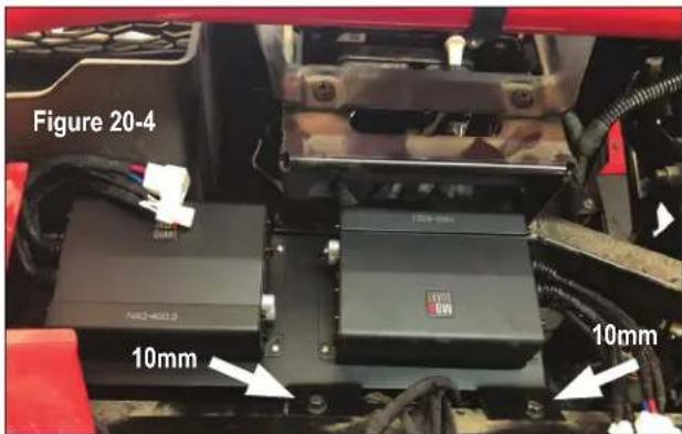
- if you have the Dynamix ^ ECU and/or OEM amplifier bracket - Tighten the remaining two (2) 10mm bolts to securely mount the dual amp plate. This is shown in Figure 20-4.
- If NO Dynamix ^ ECU or OEM amplifier bracket - Secure the dual amplifier plate. Simply substitute the (2) 10mm screws in Figure 20-4 and use the two (2) T40 screws provided with the MB Quart Stage 5 kit to securely mount the dual amp plate
STEP 3 - SECURE WIRING HARNESS
Secure the wiring harness with zip-ties to complete the installation. Ensure the routing of the harness avoids contact with any sources of heat or moving parts.
Should the Dynamix ECU or OEM amplifier (if present) ever need servicing, be sure to leave enough slack in the harness so that the dual amp plate can be removed and either set aside or flipped over as it was during initial fitting on page 14.
VEHICLE REASSEMBLY
Follow along the dual amplifier audio harness and zip-tie the harness to the vehicle to assure it doesn't come loose during rides. Do not zip-tie the harness to any heat or moisture sources. Also ensure the point at which the harness passes through the firewall grommet is sufficiently sealed with electrical tape, silicone-based caulking or equivalent. Once your harness is secure and the firewall grommet is sealed, you can begin reassembling all the panels.
Here is an important checklist so you do not forget anything:
2013-2018 RZR Models
- ENSURE FIREWALL GROMMET IS WELL SEALED WHERE HARNESS PASSES THROUGH
• REINSTALL CENTER CONSOLE - REINSTALL SEATS TIGHTEN NEGATIVE BATTERY TERMINAL FULLY
- OIL COVER ON ENGINE COMPARTMENT BEHIND THE SEATS
• REINSTALL CENTER CONSOLE - REINSTALL SEATS
- TIGHTEN NUTS ON STEERING WHEEL COLUMN (2013-2018 Models) - 40 FT/LB of TORQUE*
- FRONT OF DASH - CHECK ALIGNMENT WHERE THE DASH MEETS THE SUBWOOFER
- ZIP-TIE STAGE 5 WIRING HARNESS WHILE AVOIDING HEAT SOURCES OR MOVING PARTS
• REASSEMBLE TOP OF DASH - REPLACE HOOD
*NOTE – It is critical to the safe operation of your vehicle that the nuts holding the steering column be re-tightened to 40-foot pounds of torque.
2018.5 Turbo S and 2019+ RZR Models
- ENSURE FIREWALL GROMMET IS WELL SEALED WHERE HARNESS PASSES THROUGH
• TIGHTEN NEGATIVE BATTERY TERMINAL FULLY - REINSTALL DYNAMIX® ECU BRACKET (IF PRESENT) - TIGHTEN TWO 10MM BOLTS
- FINAL FIT OF AMPLIFIER BRACKET - TIGHTEN REMAINING TWO 10MM BOLTS FOR ECU BRACKET
- OIL COVER ON ENGINE COMPARTMENT BEHIND THE SEATS
- REINSTALL CENTER CONSOLE
- REINSTALL SEATS
- FRONT OF DASH - CHECK ALIGNMENT WHERE THE DASH MEETS THE SUBWOOFER
- ZIP-TIE STAGE 5 WIRING HARNESS WHILE AVOIDING HEAT SOURCES OR MOVING PARTS
- REASSEMBLE TOP OF DASH
- REPLACE HOOD
FINAL INSPECTION
Here is a checklist to make sure your vehicle is ready to hit the trails. You should pull & tighten everything so that you know your RZR and your audio equipment are secure.
• NUTS ON HARNESS AT THE BUS BAR
• ELECTRICAL TAPE ON THE SPLICE AT THE FIREWALL GROMMET
- SUBWOOFER MOUNT
- SUBWOOFER GLOVE BOX DOOR
- LEFT KICK PANEL ENCLOSURE MOUNT AND WIRING
• RIGHT KICK PANEL ENCLOSURE MOUNT AND WIRING
- AMPLIFIERS MOUNTED AND ALL 8 NUTS ARE SECURED TO DUAL AMPLIFIER PLATE
- NUTS ON STEERING WHEEL COLUMN (2013-2018 Models) - 40 FT/LB of TORQUE*
• HARNESSES TO AMPLIFIERS
- SUBWOOFER SPEAKER HARNESS AT AMPLIFIER
• FRONT AND REAR SPEAKER HARNESS AT AMPLIFIER
- HIDE HARNESSES UNDER CENTER CONSOLE SO NOTHING IS SHOWING OR HANGING OUT FROM UNDER SUBWOOFER ENCLOSURE OR KICK PANELS
- ACCOUNT FOR ALL YOUR TOOLS.
*NOTE – It is critical to the safe operation of your vehicle that the nuts holding the steering column in 2013-2018 models be re-tightened to 40-foot pounds of torque.
COMPLETE WIRING LAYOUT
This is a complete wiring harness layout diagram.

flowchart
graph TD
    A["Speaker Harness"] --> B["4 Seat RZs Use Provided"]
    A --> C["4 Seat RZs Use Provided"]
    A --> D["4 Seat RZs Use Provided"]
    A --> E["4 Seat RZs Use Provided"]
    A --> F["4 Seat RZs Use Provided"]
    G["Speaker Harness"] --> H["4 Seat RZs Use Provided"]
    G --> I["4 Seat RZs Use Provided"]
    G --> J["4 Seat RZs Use Provided"]
    K["Speaker Harness"] --> L["4 Seat RZs Use Provided"]
    K --> M["4 Seat RZs Use Provided"]
    N["Speaker Harness"] --> O["4 Seat RZs Use Provided"]
    N --> P["4 Seat RZs Use Provided"]
    Q["Speaker Harness"] --> R["4 Seat RZs Use Provided"]
    Q --> S["4 Seat RZs Use Provided"]
    T["Speaker Harness"] --> U["4 Seat RZs Use Provided"]
    T --> V["4 Seat RZs Use Provided"]
    W["Speaker Harness"] --> X["4 Seat RZs Use Provided"]
    W --> Y["4 Seat RZs Use Provided"]
    Z["Speaker Harness"] --> AA["4 Seat RZs Use Provided"]
    Z --> AB["4 Seat RZs Use Provided"]
    AC["Speaker Harness"] --> AD["4 Seat RZs Use Provided"]
    AC --> AE["4 Seat RZs Use Provided"]
    AF["Speaker Harness"] --> AG["4 Seat RZs Use Provided"]
    AF --> AH["4 Seat RZs Use Provided"]
    AI["Speaker Harness"] --> AJ["4 Seat RZs Use Provided"]
    AI --> AK["4 Seat RZs Use Provided"]
    AL["Speaker Harness"] --> AM["4 Seat RZs Use Provided"]
    AL --> AN["4 Seat RZs Use Provided"]
    AO["Speaker Harness"] --> AP["4 Seat RZs Use Provided"]
    AO --> AQ["4 Seat RZs Use Provided"]
    AR["Speaker Harness"] --> AS["4 Seat RZs Use Provided"]
    AR --> AT["4 Seat RZs Use Provided"]
    AU["Speaker Harness"] --> AV["4 Seat RZs Use Provided"]
    AU --> AW["4 Seat RZs Use Provided"]
    AX["Speaker Harness"] --> AY["4 Seat RZs Use Provided"]
    AX --> AZ["4 Seat RZs Use Provided"]
    BA["Speaker Harness"] --> BB["4 Seat RZs Use Provided"]
    BA --> BC["4 Seat RZs Use Provided"]
    BD["Speaker Harness"] --> BE["4 Seat RZs Use Provided"]
    BD --> BF["4 Seat RZs Use Provided"]
    BG["Speaker Harness"] --> BH["4 Seat RZs Use Provided"]
    BG --> BI["4 Seat RZs Use Provided"]
    BJ["Speaker Harness"] --> BK["4 Seat RZs Use Provided"]
    BJ --> BL["4 Seat RZs Use Provided"]
    BM["Speaker Harness"] --> BN["4 Seat RZs Use Provided"]
    BM --> BO["4 Seat RZs Use Provided"]
    BP["Speaker Harness"] --> BQ["4 Seat RZs Use Provided"]
    BP --> BR["4 Seat RZs Use Provided"]
    BS["Speaker Harness"] --> BT["4 Seat RZs Use Provided"]
    BS --> BU["4 Seat RZs Use Provided"]
    BV["Speaker Harness"] --> BW["4 Seat RZs Use Provided"]
    BV --> BX["4 Seat RZs Use Provided"]
    BY["Speaker Harness"] --> CA["4 Seat RZs Use Provided"]
    BY --> CB["4 Seat RZs Use Provided"]
    CC["Speaker Harness"] --> CD["4 Seat RZs Use Provided"]
    CC --> CE["4 Seat RZs Use Provided"]
    CF["Speaker Harness"] --> CG["4 Seat RZs Use Provided"]
    CF --> CH["4 Seat RZs Use Provided"]
    CI["Rear Pod Wing Shown with Optonal Illumination"] --> CJ["Left Speaker +/-"]
    CK["Rear Pod Wing Shown with Optonal Illumination"] --> CL["Left Speaker +/-"]
    CJ --> CJ1["Left Speaker +/-"]
    CL --> CL1["Left Speaker +/-"]
    CJ1 --> CJ1a["Left Speaker +/-"]
    CL1a --> CJ1b["Left Speaker +/-"]
    CJ2 --> CJ2a["Left Speaker +/-"]
    CJ2a --> CJ2b["Left Speaker +/-"]
    CJ2b --> CJ2c["Left Speaker +/-"]
    CJ3 --> CJ3a["Left Speaker +/-"]
    CJ3a --> CJ3b["Left Speaker +/-"]
    CJ3b --> CJ3c["Left Speaker +/-"]
    CJ3c --> CJ3d["Left Speaker +/-"]
    CJ4 --> CJ4a["Left Speaker +/-"]
    CJ4a --> CJ4b["Left Speaker +/-"]
    CJ4b --> CJ4c["Left Speaker +/-"]
    CJ5 --> CJ5a["Left Speaker +/-"]
    CJ5a --> CJ5b["Left Speaker +/-"]
    CJ5b --> CJ5c["Left Speaker +/-"]
    CJ6 --> CJ6a["Left Speaker +/-"]
    CJ6a --> CJ6b["Left Speaker +/-"]
    CJ6b --> CJ6c["Left Speaker +/-"]
    CJ7 --> CJ7a["Left Speaker +/-"]
    CJ7a --> CJ7b["Left Speaker +/-"]
    CJ7b --> CJ7c["Left Speaker +/-"]
    CJ8 --> CJ8a["Left Speaker +/-"]
    CJ8a --> CJ8b["Left Speaker +/-"]
    CJ8b --> CJ8c["Left Speaker +/-"]
    CJ9 --> CJ9a["Left Speaker +/-"]
    CJ9a --> CJ9b["Left Speaker +/-"]
    CJ9b --> CJ9c["Left Speaker +/-"]
NOTES
Use this section to record serial numbers of each product, final gain and crossover settings of amplifiers or any other wiring or installation-related details that will be helpful if you need to add on to the system or troubleshoot any unforeseen issues.


MBQuart.com #MUSIC DEFINED
FCC Notice
This equipment has been tested and found to comply with the limits for a Class B digital device, pursuant to part 15 of the FCC Rules. These limits are designed to provide reasonable protection against harmful interference in a mobile installation. This equipment generates, uses and can radiate radio frequency energy and, if not installed and used in accordance with the instructions, may cause harmful interference to radio communications. However, there is no guarantee that interference will not occur in a particular installation.
WARNING: Changes or modifications not expressly approved by the party responsible for compliance could void the user's authority to operate the equipment.
This equipment complied with FCC radiation exposure limits set forth for an uncontrolled environment. This equipment should be installed and operated with minimum distance 20cm between the radiator & your body.
WARRANTY
Maxxsonics USA Inc. warrants this product, to the original consumer purchaser, to be free from defects in material and workmanship for a period of one (1) year from the date of purchase. Maxxsonics USA Inc. will, at its discretion, repair or replace defective products during the warranty period. Components that prove to be defective in materials and workmanship under proper installation and use must be returned to the original authorized Maxxsonics USA Inc. retailer from where it was purchased. A photocopy of the original receipt must accompany the product being returned. The costs associated with removal, re-installation and freight are not the responsibility of Maxxsonics USA Inc. This warranty is limited to defective parts and specifically excludes any incidental or consequential damages connected therewith. To view the full warranty, please visit the website.
The Bluetooth ^® word mark and logos are registered trademarks owned by the Bluetooth SIG, Inc. and any use such marks by MB Quart is under license.
All product names, logos, and brands are property of their respective owners. All company, product and service names used in this literature are for identification purposes only. Use of these names, logos, and brands does not imply endorsement.
©2020 Maxxsonics USA, Inc.
MBQuart products are designed and engineered in the USA by

MAXXSONICS®
www.maxxsonics.com



- MBQUARTI® MUSIC. DEFINED.
- Installation Manual
- MBQR-STG5-2 MBQR-STG5-RC1
- WHAT'S INCLUDED
- Non-Ride Command® Package (MBQR-STG5-2 Only)
- Ride Command® Package (MBQR-STG5-RC1 Only)
- All RZR® Stage 5 System Packages (MBQR-STG5-2 or MBQR-STG5-RC1)
- WARRANTY
- TECHNICAL SUPPORT
- INSTALLATION TIME
- TOOLS AND SUPPLIES NEEDED
- SAFETY PRECAUTIONS
- PREPARATION FOR INSTALLATION
- STEP 1 - CONFIRMING POWER TO BUS BAR
- TWO RZR-TUNED STAGE 5 AUDIO SYSTEM OPTIONS!
- ABOUT RIDE COMMAND®
- VEHICLES WITH RIDE COMMAND®
- VEHICLES WITHOUT RIDE COMMAND®
- AUDIO SYSTEM ACCESSORIES FOR YOUR Polaris® RZR®
- SR1-120RGB LED RING LIGHT
- RFREM WIRELESS REMOTE
- DASH AREA DISASSEMBLY 2013-2018 (Non-Turbo S) RZR
- STEP 1 – REMOVE CENTER HOOD
- STEP 2 - REMOVE TOP OF DASH
- STEP 3 – REMOVE THE GRAB BAR
- STEP 4 - REMOVING DASH POCKET & REAR MOUNT
- DASH AREA DISASSEMBLY 2013-2018 (Non-Turbo S) RZR - Continued
- STEP 5 – REMOVE DASH FASCIA CENTER HARDWARE
- STEP 6 – REMOVE DASH FASCIA HARDWARE
- STEP 7 – REMOVE THE GLOVE BOX
- DASH AREA DISASSEMBLY 2018.5 Turbo S & 2019+ RZR (RIDE COMMAND)
- STEP 2 - REMOVE CENTER SHROUD
- STEP 3 - REMOVE FULL FRONT COVER DASH TOP ASSEMBLY
- DASH AREA DISASSEMBLY 2018.5 Turbo S & 2019+ RZR - Continued
- STEP 4 – REMOVE DYNAMIX® ECU BRACKET OR POCKET SCREW
- STEP 5 – REMOVE LOWER POCKET AND PASSENGER SIDE CUBBY
- STEP 6 – REMOVE CENTER SWITCH HARDWARE
- STEP 7 – PREPARE FINAL ELECTRONICS FOR DASH REMOVAL
- STEP 8- REMOVE DASH FASCIA
- STEP 9 – REMOVE THE GLOVE BOX
- REMOVE SEATS AND CENTER CONSOLE (ALL MODELS)
- STEP 1 – REMOVE SEATS
- STEP 2 - UNBOLT AND MARK CENTER CONSOLE HARDWARE
- STEP 3 - REMOVE CENTER CONSOLE
- INSTALL POWER HARNESS AT BUS BAR (ALL MODELS)
- STEP 1 - REMOVE RZR BUS BAR FACTORY CONNECTIONS
- STEP 2 - LAY IN HARNESS - IDENTIFY FIREWALL GROMMET
- STEP 3 - CUT OPENING IN GROMMET AND RUN WIRING THROUGH
- STEP 4 - COMPLETE BUS BAR CONNECTION
- AMPLIFIER PREPARATION AND MOUNTING (2013-2018 Models)
- STEP 1 - LOOSEN STEERING COLUMN NUTS
- STEP 2 - AMPLIFIER MOUNTING
- STEP 3 - MOUNTING PLATE INSTALLATION
- AMPLIFIER PREPARATION AND MOUNTING (2018.5 Turbo S & 2019+ Models)
- STEP 1 – DETERMINE YOUR MODEL'S OPTIONS FOR DUAL AMPLIFIER PLATE MOUNTING
- Factory-Installed (OEM) Amplifier ONLY
- Dynamix® ECU ONLY
- Factory-Installed (OEM) Amplifier AND Dynamix® ECU
- NO Factory-Installed (OEM) Amplifier OR Dynamix® ECU
- AMPLIFIER PREPARATION AND MOUNTING (2018.5 Turbo S & 2019+ Models Continued)
- STEP 3 – TRIAL FITTING THE DUAL AMP PLATE
- STEP 4 – REMOVE DUAL AMP PLATE FROM ITS LOCATION AND FLIP OVER
- SUBWOOFER ENCLOSURE MOUNTING (ALL MODELS)
- STEP 1 – POSITION SUBWOOFER ENCLOSURE
- STEP 2 – BEGIN MOUNTING ENCLOSURE
- STEP 3 - FINISH SUBWOOFER MOUNTING
- STEP 4 - ROUTE SUBWOOFER WIRING HARNESS
- AMPLIFIER AND SPEAKER WIRING HARNESS CONNECTIONS
- STEP 1 – POWER AND SPEAKER CONNECTORS AT AMPLIFIERS
- STEP 2 – ROUTE FRONT SPEAKER HARNESS
- STEP 3 - ROUTE REAR SPEAKER HARNESS
- REAR SPEAKER POD INSTALLATION
- STEP 1 - MOUNT SPEAKER PODS w/BRACKETS
- STEP 2 - CONNECT WIRING
- STEP 3 - HEAT SHRINK WIRING CONNECTIONS
- MOUNTING THE KICK PANEL SPEAKERS
- STEP 1 - MARK HOLES USING SUPPLIED TEMPLATE
- STEP 2 - DRILL HOLES
- STEP 3 - PLACE DRIVER'S SIDE KICK PANEL
- STEP 4 – PUSH OUTER BOLTS THROUGH FENDER AND MOUNT DRIVER'S SIDE KICK PANEL
- STEP 5 – CONNECT WIRE HARNESS INTO KICK PANEL
- MOUNTING THE KICK PANEL SPEAKERS (Continued)
- STEP 6 – PLACE PASSENGER SIDE KICK PANEL
- STEP 7 – PUSH OUTER BOLTS THROUGH FENDER AND MOUNT DRIVER'S SIDE KICK PANEL
- STEP 8 - CONNECT WIRE HARNESS INTO KICK PANEL
- AMPLIFIER SETTINGS
- STEP 1 – ADJUST TWO-CHANNEL AMPLIFIER
- STEP 2 - ADJUST MONO AMPLIFIER
- CONNECT RIDE COMMAND AUDIO ADAPTERS (Ride Command Models Only)
- STEP 1 - LOCATE AUDIO OUTPUT PLUGS
- STEP 2 - CONNECT ADAPTERS
- STEP 3 - CONNECT REMOTE AMP TURN-ON
- STEP 4 - CONNECT RCAs TO AMPLIFIERS
- MOUNT THE USB & 3.5mm (AUX) DASH ADAPTER (Non-Ride Command)
- STEP 1 - MOUNT ADAPTER
- STEP 2 - CONNECT TO SOURCE
- INSTALLING THE SOURCE UNIT (Non-Ride Command-Equipped)
- STEP 1 – RUN CONNECTIONS TO SOURCE UNIT AREA
- STEP 2 - MAKE SOURCE UNIT CONNECTIONS
- STEP 3 - SECURE THE SOURCE UNIT
- INITIAL TESTING
- STEP 1 – RECONNECT THE BATTERY
- STEP 2 – TURN ON IGNITION
- STEP 3a – INITIAL CHECKS (Non-Ride Command)
- STEP 3b - INITIAL CHECKS (Ride Command-Equipped)
- Step 4 - SPEAKER AND AMPLIFIER CHECKS (all systems)
- FINE TUNING
- Settings
- Level Setting
- THIS IS NOT A VOLUME CONTROL!
- FINAL AMPLIFIER MOUNTING (2018.5 Turbo S & 2019 Models)
- STEP 1 – DETERMINE YOUR MODEL'S OPTIONS FOR DUAL AMPLIFIER PLATE FINAL MOUNTING
- FINAL AMPLIFIER MOUNTING (2018.5 Turbo S & 2019+ Models Continued)
- STEP 2 – FINAL FITTING THE DUAL AMP PLATE
- STEP 3 - SECURE WIRING HARNESS
- VEHICLE REASSEMBLY
- 2013-2018 RZR Models
- Turbo S and 2019+ RZR Models
- FINAL INSPECTION
- COMPLETE WIRING LAYOUT
- NOTES
- MBQuart.com #MUSIC DEFINED
- FCC Notice
Marque : MB QUART
Modèle : MBQR-STG5-RC1
Catégorie : Autoradio