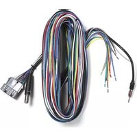
70-1856 - Câble électrique Metra - Notice d'utilisation et mode d'emploi gratuit
Retrouvez gratuitement la notice de l'appareil 70-1856 Metra au format PDF.


| Type de produit | Adaptateur de faisceau de câbles pour autoradio |
| Marque | Metra |
| Modèle | 70-1856 |
| Dimensions approximatives | 15 x 10 x 3 cm |
| Poids approximatif | 0,1 kg |
| Alimentation | 12 V CC (batterie véhicule) |
| Fonctions principales | Permet la connexion d’un autoradio après-vente au faisceau d’origine du véhicule ; conserve les fonctions d’origine (antenne, haut-parleurs, alimentation) |
| Entretien et nettoyage | Essuyer avec un chiffon sec et non pelucheux |
| Sécurité | Utiliser uniquement dans un véhicule avec système électrique 12 V ; débrancher la batterie avant installation |
| Pièces détachées et réparabilité | Non réparable ; aucune pièce détachée disponible |
| Informations générales | Fabriqué en Chine ; compatible avec de nombreux modèles de véhicules (consulter le guide d’application Metra) |
FOIRE AUX QUESTIONS - 70-1856 Metra
Questions des utilisateurs sur 70-1856 Metra
0 question sur cet appareil. Repondez a celles que vous connaissez ou posez la votre.
Poser une nouvelle question sur cet appareil
Téléchargez la notice de votre Câble électrique au format PDF gratuitement ! Retrouvez votre notice 70-1856 - Metra et reprennez votre appareil électronique en main. Sur cette page sont publiés tous les documents nécessaires à l'utilisation de votre appareil 70-1856 de la marque Metra.
MODE D'EMPLOI 70-1856 Metra
Wiring Adaptor
IMPORTANT
120 70-1856
Before starting, compare items on your invoice with items received. Thoroughly check packing materials. If an item is missing, please call:
Crutchfield at1-888-955-6000
Revision 06/22/09
STEP 1 -- CONNECT WIRES
Match wires below to the matching function of each wire on your receiver (refer to instructions supplied with receiver). The wire colors of your new receiver may, or may not, match the wire colors of the adaptor. Match adaptor and receiver wires by function, disregarding color.
Connect Black wire to Ground wire of new receiver.
▶ Individually tape off any unused wires.
▶ Make final wiring connections following instructions on the next page.
Plug connectors into matching inputs.
STEP 2 -- INSTALL
![graph TD A["Terminal"] --> B["To Receiver"] B --> C["Red - 12 Volts Switched Power"] B --> D["Yellow - 12 Volts Constant Power"] B --> E["Black - Chassis Ground"] B --> F["Gray - Right Front Speaker Positive"] B --> G["Gray/Black - Right Front Speaker Negative"] B --> H["White - Left Front Speaker P…](/content/2026/06/1355155/images/b468e2dd91f304dca4a5a34a7c8f23e3a35b801f2e0ecbcaab6947020bf39971.jpg)

Copyright 2009 Crutchfield Corporation
CRIMP METHOD SOLDER
A. Strip wires back 1/2".

C. Squeeze middle of cap for tight connection.
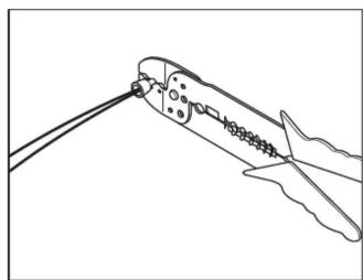
B. Twist wires together and insert in crimp cap.
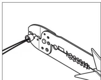
A. Strip wires back 1/2".

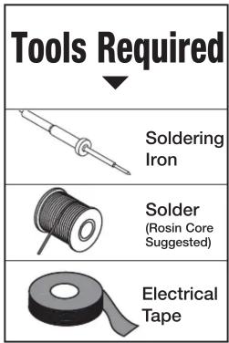
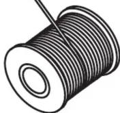
D. Tape
CRUTCHFIELD®
CRUTCHFIELD.COM
Copyright 2009 Crutchfield Corporation
Marque : Metra
Modèle : 70-1856
Catégorie : Câble électrique