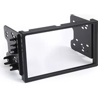
95-7951 - Kit d'encastrement Metra - Notice d'utilisation et mode d'emploi gratuit
Retrouvez gratuitement la notice de l'appareil 95-7951 Metra au format PDF.


| Type de produit | Kit d'encastrement pour autoradio |
| Marque | Metra |
| Modèle | 95-7951 |
| Dimensions (approx.) | 18 x 5 x 2 cm |
| Poids net | 0.3 kg |
| Matériau principal | Plastique ABS et métal |
| Alimentation | Aucune (kit passif) |
| Fonctions principales | Installation d’un autoradio après-vente, adaptation du faisceau électrique, fixation dans le tableau de bord |
| Compatible avec | Autoradios standard DIN |
| Contenu du kit | Cadre de montage, faisceau d’adaptation, antenne adaptateur, vis et instructions |
| Entretien et nettoyage | Nettoyer avec un chiffon doux et sec. Ne pas utiliser de solvants. |
| Sécurité | Débrancher la batterie avant l’installation. Respecter les instructions de montage. |
| Pièces détachées et réparabilité | Pièces disponibles sur demande auprès de Metra. Kit non réparable, remplacer si endommagé. |
| Informations générales | Kit conçu pour une installation facile dans la plupart des véhicules. Notice d’utilisation fournie. |
FOIRE AUX QUESTIONS - 95-7951 Metra
Questions des utilisateurs sur 95-7951 Metra
0 question sur cet appareil. Repondez a celles que vous connaissez ou posez la votre.
Poser une nouvelle question sur cet appareil
Téléchargez la notice de votre Kit d'encastrement au format PDF gratuitement ! Retrouvez votre notice 95-7951 - Metra et reprennez votre appareil électronique en main. Sur cette page sont publiés tous les documents nécessaires à l'utilisation de votre appareil 95-7951 de la marque Metra.
MODE D'EMPLOI 95-7951 Metra
APPLICATIONS
See application list inside
Chevrolet/Suzuki/Pontiac multi-kit 2004 - 2008
95-7951
KIT FEATURES
- Double DIN radio provision
- Stacked ISO units provision
KIT COMPONENTS
• A) Double DIN Trim Plate • B) Double DIN Brackets

A

B

WIRING & ANTENNA CONNECTIONS (Sold Separately)
Wiring Harness:
• 70-2105 GM harness 2006-up
• 70-8405 GM/Suzuki/Daewoo harness 1999-up
Antenna Adapter:
• 40-CR10 Chrysler antenna adapter 2002-up
TOOLS REQUIRED
Panel Removal Tool • Phillips Screwdriver • Small Flat Blade Screwdriver

METRA. THE WORLD'S BEST KITS. TM

1-800-221-0932

metraonline.com
© COPYRIGHT 2004-2011 METRA ELECTRONICS CORPORATION
Applications
Chevrolet
Aveo 2004-2006
Aveo Hatchback 2007-2008
Suzuki
Forenza 2004-2008
Reno 2005-2008
Verona 2004-2006
Pontiac
G3 Hatchback 2007
Table of Contents
Dash Disassembly
- Chevrolet Aveo 2004-2006....3....
— Chevrolet Aveo Hatchback 2007-2008....3.... - Pontiac G3 Hatchback 2007. . . . . . . . . . . . . . . . . . . . . . . . . . .
— Suzuki Forenza 2004-2008....4-5....
— Suzuki Reno 2005-2008 ..... 4-5. - Suzuki Verona 2004-2006. . . . . . . . . . . . . . . . . . . . . . . .
Kit Assembly
- Double DIN radio provision....7-8....
- Stacked ISO mount units provision 9-10
Caution
Metra recommends disconnecting the negative battery terminal before beginning any installation. All accessories, switches, and especially air bag indicator lights must be plugged in before reconnecting the battery or cycling the ignition.
*NOTE: Refer also to the instructions included with the aftermarket radio.

KNOWLEDGE IS POWER
Enhance your installation and fabrication skills by enrolling in the most recognized and respected mobile electronics school in our industry. Log onto www.installerinstitute.com or call 800-354-6782 for more information and take steps toward a better tomorrow.

Metra recommends MECP certified technicians
Chevrolet Aveo 2004-2006 Chevrolet Aveo Hatchback 2007-2008 Pontiac G3 Hatchback 2007
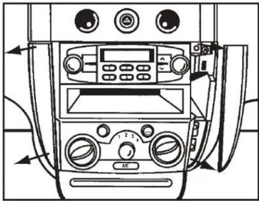
- Unclip and remove the trim panels from both sides of radio/climate controls. (Figure A)
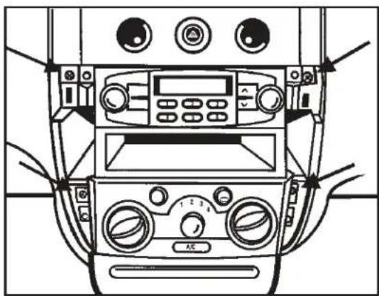
- Remove (4) Phillips screws securing the radio. Unplug and remove radio. (Figure B)
Continue to kit assembly
(Figure A)
(Figure B)
Suzuki Forenza 2004-2008 Suzuki Reno 2005-2008
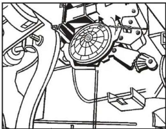
- Disconnect air selector cable on driver's side of center console behind dash above accelerator pedal. (Figure A & B)
- Open glove box and remove (5) Phillips screws ((3) on top and (2) on bottom) then remove entire glove box.
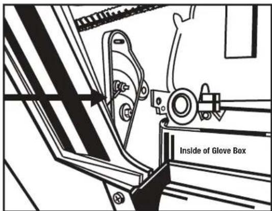
- Disconnect temperature selector cable on passenger side of center console behind glove box. (Figure C)
Continued on next page

(Figure A)
(Figure B)
(Figure C)
Suzuki Forenza 2004-2008 Suzuki Reno 2005-2008
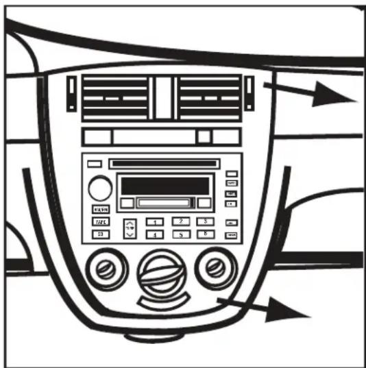
- Unsnap and remove entire panel surrounding radio. NOTE: The clips holding radio panel to dash are very strong. (Figure D)
- Remove (4) 10 mm bolts securing radio. Unplug and remove radio. (Figure E) Continue to kit assembly
(Figure D)

(Figure E)
Suzuki Verona 2004-2006
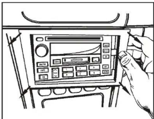
- Unclip and remove the trim panel surrounding the radio. (Figure A)
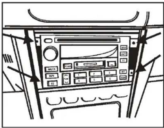
- Remove (4) Phillips screws from radio. Unplug and remove radio. (Figure B) Continue to kit assembly
(Figure A)
(Figure B)
Double DIN radio provision
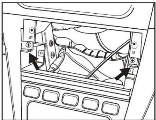
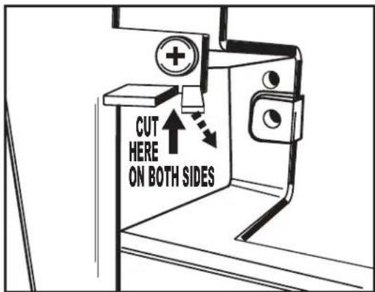
NOTE: For the Chevrolet Aveo 2004-06, Chevrolet Aveo Hatchback 2007-08, Pontiac G3 Hatchback 2007 and Suzuki Verona 2004-06, cut and remove front lower mounting tabs from the Double DIN trim plate (Figure A). For the Suzuki Forenza 2004-08 and the Suzuki Reno 2005-08, cut the rear lower mounting tabs (Figure B).
NOTE: The Verona 2004-2006 sub dash will need to be trimmed slightly for proper fit. Refer to illustration. (Figures C and D)
Continued on next page

(Figure A)

(Figure B)
(Figure C)
(Figure D)
Double DIN radio provision
- Locate the factory wiring harness in the dash. Metra recommends using the proper mating adapter from Metra or AXXESS. Re-connect the negative battery terminal and test the unit for proper operation.
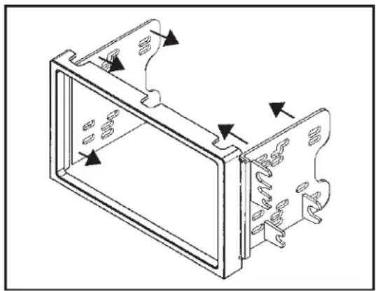
- Snap the Double DIN brackets to the outside edge of the Double DIN trim plate. (Figure E)
- Slide the Double DIN radio into the bracket/trim plate assembly and secure the radio to the assembly using the screws supplied with the radio. (Figure F)
- Reassemble dash in reverse order of disassembly.
(Figure E)

(Figure F)
Stacked ISO mount units provision
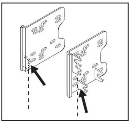
NOTE: For the Chevrolet Aveo 2004-06, Chevrolet Aveo Hatchback 2007-08, Pontiac G3 Hatchback 2007 and Suzuki Verona 2004-06, cut and remove front lower mounting tabs from the Double DIN trim plate (Figure A). For the Suzuki Forenza 2004-08 and the Suzuki Reno 2005-08, cut the rear lower mounting tabs (Figure B).
NOTE: The Verona 2004-2006 sub dash will need to be trimmed slightly for proper fit. Refer to illustration. (Figures C and D)
Continued on next page
(Figure A)

(Figure B)

(Figure C)

(Figure D)
Stacked ISO mount units provision
- Locate the factory wiring harness in the dash. Metra recommends using the proper mating adapter from Metra or AXXESS. Re-connect the negative battery terminal and test the unit for proper operation.
- Snap the Double DIN brackets to the outside edge of the Double DIN trim plate. (Figure E)
- Slide the stacked ISO units into the bracket/trim plate assembly and secure the units to the assembly using the screws supplied with the units. (Figure F)
- Reassemble dash in reverse order of disassembly.

(Figure E)
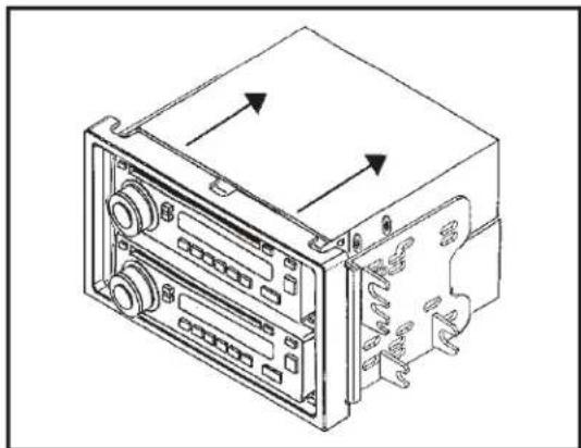
(Figure F)


- APPLICATIONS
- CHEVROLET/SUZUKI/PONTIAC MULTI-KIT 2004 - 2008
- KIT FEATURES
- KIT COMPONENTS
- WIRING & ANTENNA CONNECTIONS (SOLD SEPARATELY)
- TOOLS REQUIRED
- TABLE OF CONTENTS
- DASH DISASSEMBLY
- KIT ASSEMBLY
- CAUTION
- KNOWLEDGE IS POWER
- CHEVROLET AVEO 2004-2006 CHEVROLET AVEO HATCHBACK 2007-2008 PONTIAC G3 HATCHBACK 2007
- SUZUKI FORENZA 2004-2008 SUZUKI RENO 2005-2008
- SUZUKI VERONA 2004-2006
- DOUBLE DIN RADIO PROVISION
- STACKED ISO MOUNT UNITS PROVISION
Marque : Metra
Modèle : 95-7951
Catégorie : Kit d'encastrement