
T105RF - Thermostat Salus - Notice d'utilisation et mode d'emploi gratuit
Retrouvez gratuitement la notice de l'appareil T105RF Salus au format PDF.


| Type de produit | Thermostat d'ambiance programmable |
| Marque | Salus |
| Modèle | T105RF |
| Alimentation | 2 piles AA (1,5 V) |
| Fréquence radio | 868 MHz |
| Portée radio | Jusqu'à 30 m en intérieur |
| Affichage | Écran LCD digital |
| Dimensions | 130 x 85 x 25 mm |
| Poids | 150 g (piles incluses) |
| Plage de température de consigne | 5 °C à 35 °C |
| Précision | ±0,5 °C |
| Programmation | Jusqu'à 4 à 8 périodes par jour selon version |
| Fonctions | Programmation hebdomadaire, mode manuel, mode vacances, protection antigel |
| Entretien | Nettoyer avec un chiffon doux sec ; ne pas utiliser de produits chimiques |
| Sécurité | Protection contre les surtensions intégrée |
| Piles | Utiliser des piles alcalines ; remplacer environ une fois par an |
| Réparabilité | Pièces détachées disponibles auprès du fabricant ; réparation par professionnel recommandée |
FOIRE AUX QUESTIONS - T105RF Salus
Questions des utilisateurs sur T105RF Salus
0 question sur cet appareil. Repondez a celles que vous connaissez ou posez la votre.
Poser une nouvelle question sur cet appareil
Téléchargez la notice de votre Thermostat au format PDF gratuitement ! Retrouvez votre notice T105RF - Salus et reprennez votre appareil électronique en main. Sur cette page sont publiés tous les documents nécessaires à l'utilisation de votre appareil T105RF de la marque Salus.
MODE D'EMPLOI T105RF Salus
SALUS CONTROLS
GB T105RF - WIRELESS THERMOSTAT

natural_image
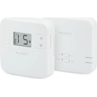
Two white electronic devices: a digital display with a timer and a connected smart home (no visible text or symbols)INTRODUCTION
This thermostat can replace most common residential thermostats and is designed to be used with electric, gas or oil heating control system or cooling system. Unlike ordinary single unit design thermostats, this unit is a new type of thermostat separating the thermostat function into two units. The Receiver serves for wiring connections and heat/cool on/off control. The Control Centre serves as user interface and temperature sensing/control. The two units are linked by RF. The advantage is that users can put the Control Centre nearby and can read/control the temperature of the living area.
SPECIFICATION
Clock accuracy:
Temp. measurement:
Temp. accuracy
Temperature Control:
Span:
Air conditioner cycle time:
Operation temperatur
Storage tempe
Power Source
Receiver:
Size and Weight:
Receiver:
Frequency:
+/- 60 seconds/month
0°C to 40°C in 0.2°C resolution
+/- 1°C at 20°C
7°C to 30°C in step of 0.2°C
0.4, 0.8, 1.4 or 1.8°C
3 minutes
0°C to 40°C
-10°C to 60°C
Control Centre 2 AA (LR6) batteries
230VAC 50Hz 16A resistive, 5A inductive
Control Centre 116 x 100 x 23.5mm, 126g
128 x 97 x 37mm, 190g
868 Mhz
Features
Several useful functions and operating modes have been incorporated to suit a variety of customer needs besides all the features associated with the state-of-the-art programmable thermostat.
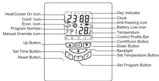
Control Centre
- Can be placed anywhere in the home to detect and control the temperature of an area of the user's choice. Not limited by power control wiring locations.
- Link with the Receiver via RF Control distance 70M open site - LCD shows the "need to know" information only, which is easier to understand.
· Real time clock with day of the week display
Room temperature display
Control profile display
Simplified temperature adjustment - Simplified programming procedure
6 pre-defined control profiles 3 user programmable control profiles
Protection against freezing Temporary set-temperature override
User selectable temperature span; User selectable heater/ cooler operation mode
Slim housing design
EL backlight
Receiver

- Linked with Control Centre via RF.
- Powered by line voltage only. No battery required.
- Two LED indicators for power and output status.
INSTALLATION OF RECEIVER
Caution
-
The appliance can only be mounted indoors and in areas free from any water or moisture.
-
A suitable fuse with a rating not exceeding 13A, should be in the power line.
- Observe the national regulations for wiring.
- A qualified electrician is recommended for installation and servicing. This thermostat has been designed for simple and quick installation requiring only a few tools. Only the Receiver needs to be installed.
Required Tools
- Hammer • Masking tape • Screwdriver
- Drill and 3/16" drill bit (if not installed on a junction box)
RF Address Code Setting
If there is another user nearby, e.g. in the next house, your receiver maybe fault triggered by their transmitter. You may select a different RF address code to prevent this. Receiver can only response to RF coding with the same address code setting as its own address code.
- To adjust address code of Control Center Receiver, simply left or right of the 5 dip switch levers.
- To adjust address code of Control Centre, open the housing of the transmitter unit. See battery replacement section on how to open the
housing.
Caution:
- Address code of Control Centre must be the same as address code of Receiver. For any on position of address code # in Control Centre, the same address code # of Receiver must be switched to ON.
- Disconnect AC power and remove batteries prior to adjusting address code.
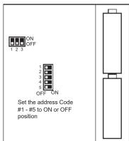
CONTROL CENTRE
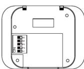
RECEIVER
Removing your old thermostat
CAUTION : to avoid electric shock, isolate the power of the heating/ cooling system at the main power box in your home. Read the following instructions carefully before disconnecting the wires.
- Turn off your old thermostat.
- Remove the cover from the old thermostat.
- Unscrew the old thermostat from the wall plate.
- Now find the screws attaching the wall plate to the wall, and remove them. You should now be able to pull the wall plate a small distance from the wall. Do not disconnect any wire yet, simply locate the wires.
WARNING: After removing the wall plate, if you find that it is mounted on a junction box (e.g. a box similar to one behind a light switch or electric outlet), high voltage circuit may be present and there is a danger of electric shock. Please consult a qualified electrician.
Choosing a Location
Note: for a new installation, choose a mounting location about five feet (1.5 metres) above the floor in an area with good air circulation and away from:
- Drafts.
- All products
- Radiant heat from the sun or appliances.
- Concealed pipes and chimneys.
Mounting the Receiver onto the wall/junction box
- Remove the back plate from the Receiver.
- Mark the holes position
- Drill two holes and insert the plastic anchors carefully into the holes,
fasten the back plate to the wall with 2 screws. - Connect the wires - see wiring diagram
- Push on the wires in the wall.
- Securely fasten the Receiver to the back plate.
WIRING DIAGRAM
RECEIVER WIRING TERMINALS
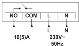
| Terminal | Identifier | Description |
| 1 | NO | Normally Open [N/O] |
| 2 | COM | Linked Live feed (230V AC heating applications only) |
| 3 | L | Live feed (230V AC) |
| 4 | N | Neutral |
SETTING OF CONTROL CENTRE
Heater/Cooler Selection
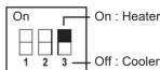
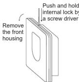
Before making any selection in the control centre, its back housing must be removed as follows: Inside the Control Centre after the back housing is removed, you can find the DIP switch.
These three switches are used to control the span and heat/cool system. Set the DIP switch (position 3) according to your selection of heater system or cooler system as the following diagram.
Temperature Span Selection
Span is the temperature difference between the turn on temperature and turn off temperature. For example, in heating systems, if you set temperature to 20^ C and span to 0.8^ C, the heater will operate when the room temperature drops to 19.2^ C and turns off when the temperature rises to 20.8^ C. Set the DIP switch (position 1 & 2) according to your selection of temperature span as the following diagram.
| 1 | 2 | Span |
| ON | ON | 0.4°C |
| OFF | ON | 0.8°C |
| ON | OFF | 1.4°C |
| OFF | OFF | 1.8°C |
Battery Installation
Your thermostat uses two (2) "AA" size batteries to operate. To power-up the unit, insert two "AA" batteries into the battery compartment of the front housing. When power is applied for the first time, the display must show time and the day as well as the room temperature (for example 28.5°C).
If the display is different, press the RESET button. Use a fine probe such as straightened paper clip to gently push the RESET button.
After installation of the batteries, push back the rear housing to the control centre and then the stand. Before turning on the main switch of the system, press the reset button once. The thermostat is ready for use.
BATTERY REPLACEMENT
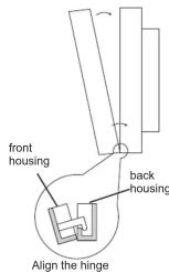
It is recommended that the batteries be replaced when the display is showing the battery-low icon. To replace the battery,
1. Turn off the power of the Receiver first
2. Remove the back housing and stand of the Desktop Unit.
3. Replace the old batteries with 2 new AA alkaline batteries
4. Replace the back housing and stand.
5. Press the reset button once and then turn on the power switch of the Receiver
Setting Clock
- Press the SET TIME button to clear all digits except the day indicator and the time display. The day indicator is flashing.
- While day indicator is flashing, press UP or DOWN button to adjust.
- Press the SET TIME button again, hour digits are flashing instead of day indicator. Press UP or DOWN button to adjust. Press and hold the UP or DOWN button to speed up the adjustment rate.
- Press the SET TIME button again, minute digits are flashing instead of hour digit. Press UP or DOWN button to adjust. Press and hold the UP or DOWN button to speed up the adjustment rate.
- Press the SET TIME button again to return to normal operation mode.
- The unit will return to normal operation mode if no key is pressed for 15 seconds.
Setting Control Temperature
- Press the SET TEMPERATURE button to display the pre-defined set temperature.
- Press the CONF/ECON button to toggle between the setting of economic mode and comfortable mode.
- Press the UP or DOWN button to increase/decrease the set temperature by 0.2°C.
- Press the SET TEMPERATURE button again to save the set temperature.
- The unit will return to normal operation mode if no button is pressed for 15 seconds.
- The default setting of comfortable mode is 21^ for heater mode and 23^ for cooler mode. The economic mode is 18^ for heater mode and 26^ for cooler mode.
SETTING PROGRAM
i) Select Week-Day
- Press the SET PROGRAM button, the day indicator shows the program day and is flashing. Program number indicator shows the current program for the selected day.
- Press the UP or DOWN button to select the day needed to program. You can select the whole week, working day, weekend, or individual day to program.
tceleS )ii Control profile pre-defined
- Press the SET PROGRAM button again, the day indicator stops flashing and the program number starts flash.
- Press the UP or DOWN button to select the program profile. P1-P6 are predefined programs. Their profiles are shown as below.
- If any of these programs are selected, press the SET PROGRAM button again to confirm this program for the specified day and return to normal operation mode.
- Press the button to toggle the control temperature setting and advance the setting hour digit by one.
- Press the "P" button to terminate the setting procedure and to return to normal operation mode.
- The setting procedure will terminate automatically when no button is pressed for 15 seconds.
| Program number | Program profile |
| Program 1:Factory Preset"Whole day Comfort" | |
| Program 2:Factory Preset"Whole day Econ" | |
| Program 3:Factory Preset"Holiday" | |
| Program 4:Factory Preset"Whole day (A)" | |
| Program 5:Factory Preset"Whole day (B)" | |
| Program 6:Factory Preset"Half-day work" |
Testing the RF Transmission Range
- Press UP button until the setpoint temperature is higher than room temperature by a few degrees.
- Wait for a few seconds
- Check the green LED. It should be On.
- If the LED is not On, try to place the Control Centre closer to the Receiver. Press the Down button to adjust the setpoint temperature to be lower than room temperature to "turn off" the receiver.
- Repeat steps 1 to 3
- The receiving range between Control Centre and Receiver is 70M in open area. When placed indoors, this distance may be shorter because of blocking by concrete walls etc, but is enough for most household applications.
- Press RESET button after receiving range testing.
TEMPORARY OVERRIDE
Override the Operation Mode
At the normal operation mode, press the CONF/ECON button to toggle the current set temperature to comfortable mode or economic mode. If the operation mode is being overridden, the HAND icon will be turned on with the current operation mode icon. Override the Setting Temperature
- In the normal operation mode, the current set temperature can be overridden by pressing the UP or DOWN button. When in override, the new set temperature will be displayed with turning the HAND icon on and both the CONF and ECON icons off.
- Press any button (except the UP or DOWN button), this will terminate the setting procedure and will revert back to normal mode with the new setting.
- The unit will revert to normal operation mode automatically when no button is pressed for 15 seconds.
ANTI-FREEZING MODE
- Pressing the UP and DOWN buttons simultaneously will activate the anti-freezing mode (for heater mode only). The ANTIFREEZING icon
and the HAND icon will be turned on while both the COMF and ECON icon will be turned off. - Pressing any button will terminate the antifreezing mode and revert to
normal operation mode. 3. The default set temperature for the anti-freezing mode is 7^ .
BACKLIGHT
Press the BACKLIGHT button to turn on the backlight. The backlight will switch off when no button is pressed for 15 seconds.
POWER SWITCH
There is a power switch on the Receiver. When there is no demand to turn on the heating/cooling device, e.g. when you go on holiday, it is recommended to turn the power switch to the Off position.
LED INDICATOR
There are two LEDs on the Power Control Unit as status indicators: 1. Red LED turns on as long as there is power to the unit. When there is no power to the unit or when power switch underneath the front cover is put at the Off position, the red LED is Off.
2. Green LED turns on as long as the heating/cooling device is energised.
SALUS 2-Year Guarantee
SALUS Controls guarantees to you, as purchaser, that the enclosed product will be free from defects in material, workmanship or design under normal use or service for a period of 2 years.
This guarantee is not assignable. Our liability to you, under this guarantee is limited to repairing or replacing any part which we find to be defective in material, workmanship or design, free of charge to the customer, upon sending the product with proof of date of purchase, postage paid to SALUS Controls plc, SALUS House, Dodworth Business Park, Whinby Road, Dodworth, Barnsley S75 3SP.
The terms of this guarantee will not apply in the following circumstances: if the product has been modified, dismantled, contaminated, damaged, neglected or otherwise abused or altered following the date of purchase, or if it fails to operate due to incorrect siting, installation, maintenance or inadequate or over voltage AC electrical power, or damage caused by failure to abide by the instructions supplied.
The liability of SALUS Controls plc, arising from the sale of this product or under the terms of this guarantee shall not in any case exceed the cost of replacement of the product. In no case, shall SALUS Controls plc be liable for consequentail loss or damage resulting from the failure of the product or the breach of this or any other guarantee, express or implied or damage caused by failure to abide by the instructions supplied.
This guarantee does not affect your statutory rights.
SALUS Controls plc
SALUS House,
Dodworth Business Park South,
Dodworth, Barnsley, S75 3SP
Tel: +44 (0) 1226 323961
Web: www.salus-tech.com
- SALUS CONTROLS
- GB T105RF - WIRELESS THERMOSTAT
- INTRODUCTION
- SPECIFICATION
- Features
- Control Centre
- Receiver
- INSTALLATION OF RECEIVER
- Caution
- Required Tools
- RF Address Code Setting
- Caution:
- Removing your old thermostat
- Choosing a Location
- Mounting the Receiver onto the wall/junction box
- WIRING DIAGRAM
- RECEIVER WIRING TERMINALS
- SETTING OF CONTROL CENTRE
- Heater/Cooler Selection
- Temperature Span Selection
- Battery Installation
- Setting Clock
- Setting Control Temperature
- SETTING PROGRAM
- i) Select Week-Day
- tceleS )ii Control profile pre-defined
- Testing the RF Transmission Range
- TEMPORARY OVERRIDE
- Override the Operation Mode
- ANTI-FREEZING MODE
- BACKLIGHT
- POWER SWITCH
- LED INDICATOR
- SALUS 2-Year Guarantee
- SALUS Controls plc
- SALUS House,
Marque : Salus
Modèle : T105RF
Catégorie : Thermostat