DV-2A - Sèche-linge SAMSUNG - Notice d'utilisation et mode d'emploi gratuit
Retrouvez gratuitement la notice de l'appareil DV-2A SAMSUNG au format PDF.


| Type de produit | Sèche-linge |
| Marque | Samsung |
| Modèle | DV-2A |
| Capacité de séchage | 8 kg |
| Dimensions (L × H × P) | 600 × 850 × 600 mm |
| Poids net | 45 kg |
| Alimentation électrique | 220-240 V, 50 Hz, 16 A |
| Puissance nominale | 2800 W |
| Type de séchage | Condensation |
| Programmes de séchage | Cotons, Synthétiques, Délicats, Express, Coton repassage facile |
| Options supplémentaires | Départ différé, Sécur enfant, Niveau de séchage ajustable |
| Système de filtration | Filtre à peluches amovible et lavable |
| Réservoir d'eau de condensation | Capacité 4,5 L, vidange manuelle ou raccordement à l'égout |
| Classe énergétique | A++ (échelle de A+++ à D) |
| Consommation annuelle d'énergie | 220 kWh |
| Niveau sonore | 65 dB(A) |
| Nettoyage du filtre | Après chaque cycle, nettoyer le filtre à peluches |
| Nettoyage du condenseur | Tous les 10 cycles, rincer le condenseur à l'eau claire |
| Pièces détachées disponibles | Filtre à peluches, courroie, résistance, condensateur, pompe de vidange |
| Indice de réparabilité | 7,8 / 10 (selon la législation en vigueur) |
| Garantie | 2 ans (pièces et main-d'œuvre) |
FOIRE AUX QUESTIONS - DV-2A SAMSUNG
Questions des utilisateurs sur DV-2A SAMSUNG
0 question sur cet appareil. Repondez a celles que vous connaissez ou posez la votre.
Poser une nouvelle question sur cet appareil
Téléchargez la notice de votre Sèche-linge au format PDF gratuitement ! Retrouvez votre notice DV-2A - SAMSUNG et reprennez votre appareil électronique en main. Sur cette page sont publiés tous les documents nécessaires à l'utilisation de votre appareil DV-2A de la marque SAMSUNG.
MODE D'EMPLOI DV-2A SAMSUNG
side vent kit installation instructions
Description: Exhaust kit for venting left and right side, or base
DC68-01052Y-05_EN
CHECKING THE INSTALLATION PARTS
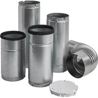
Side Vent Kit Includes:

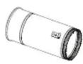
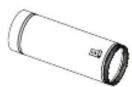
Vent cap Elbow Duct Front Duct Front-




Bottom
※ Attached label help you recognize each duct.


To avoid risk of electrical shock, personal injury or death; disconnect electrical power before servicing
Wear eye protection before performing this installation
PROCEDURE
The following instruction covers exhausting a dryer either through the left or right side of the cabinet, or through the base. It is recommended a qualified Service Technician do the installation of this kit and dryer.
INSTALLING THE SIDE VENT KIT
- For easier installation, removing the front assembly, tumbler and drive belt is recommended. * Refer to service manual for disassembly and reassembly of dryer
- Remove the knockout from either of the left or right side panel, or base. Strike it with a hammer and chisel very close to the seam. One to three sharp blows will remove it. Do not strike the middle of the knockout.

WARNING: Wear safety glasses.

natural_image
Close-up of a hand using a tool to cut or repair a car interior (no visible text or symbols)- Remove the exhaust duct cover. (Type B only)

natural_image
Close-up of a mechanical component with a circular hole and label 'Type A' (no other text or symbols visible)
natural_image
Close-up of a mechanical component with circular annotations and label 'Type B' (no readable text or symbols beyond labels)- Remove the old exhaust duct from blower housing.

natural_image
Close-up of a white mechanical component with a cylindrical shaft and circular opening, labeled 'Type A' (no other text or symbols visible)
natural_image
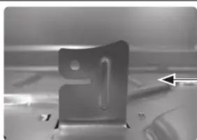
Close-up of a cylindrical mechanical component inside a transparent chamber, labeled 'Type B' (no other text or symbols visible)- Raise guide plate to about 90 degree, using a flat-blade screwdriver. The guide plate will support the exhaust duct(f).
natural_image
Close-up of a metallic mechanical component with a 3D arrow pointing to it (no visible text or symbols)
natural_image
Interior view of a mechanical or electrical enclosure with visible wiring and components (no text or symbols)FOR LEFT AND RIGHT SIDE
- Insert new exhaust Duct Front supplied with kit into blower housing. Rotate the duct to engage duct clip into tab extending up from base frame.

natural_image
Interior view of a mechanical assembly with visible components and a highlighted cylindrical component (no text or symbols)
natural_image
Close-up of a mechanical device with a large cylindrical component and a curved arrow pointing to it (no visible text or symbols)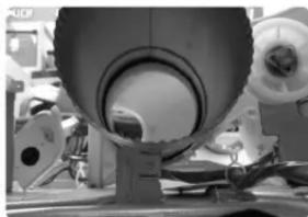
natural_image
Close-up of industrial machinery components with no visible text or symbols
natural_image
Interior view of an industrial machine with hoses and control panel (no visible text or symbols)
natural_image
Close-up of a mechanical component with coiled tubing and a hand adjusting it (no visible text or symbols)- Insert the elbow supplied in the kit into exhaust duct (F) and through the left or the right (Electric models only) toward the outlet hole depending on which direction to be exhausted.
- For side venting (left or right) insert the Exhaust Duct Back into the elbow and out cabinet side.
※ For left side venting use “Duct Back-Left”, for right side venting use “Duct Back-Right” separately.
For these models DV56H9000E*, DV56H9100E*, use the "Duct-Back Left" (BACK-LEFT) instead of "Duct-Back Right" for RIGHT SIDE VENTING. - Tape each joint with the duct tape.
Caution: Internal duct joints must be secured with tape; otherwise, they may separate and cause a safety hazard.
-
Drill a 1/8" hole using a hand drill in the frame and fix the bracket of the duct by fastening the screw.
※ The screw is not supplied with the kit. You may use the screw that you remove in the step 3. -
Reinstall the exhaust duct cover on rear of cabinet.
- Insert the vent cap supplied with the kit into rear exhaust hole left by old duct.
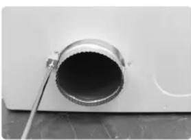
natural_image
Close-up of a metallic cylindrical component with a dark central hole, mounted on a flat surface (no text or symbols visible)
natural_image
Close-up of a metallic electronic component with a circular hole and internal structure, labeled 'Type A' below (no other text or symbols)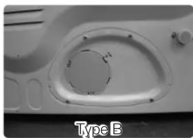
natural_image
Close-up of a mechanical component with a circular hole and labeled 'Type B' (no other text or symbols visible)FOR BOTTOM PLATE
- Assemble The Duct Front-Bottom and The Elbow.
-
Insert the assembled elbow and duct into the hole at the bottom as shown by the figure.
-
Pull the Duct Front-Bottom forwards to insert it into the Fan Housing.

natural_image
Close-up of industrial piping and valves in a factory setting (no visible text or symbols)
natural_image
Close-up of a mechanical assembly with hoses and a central bearing (no visible text or symbols)- Put the duct over on the tab extended from the base frame.

natural_image
Close-up of a turbine blade and rotor blades with a circular inset showing a gear (no text or symbols)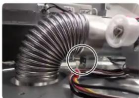
natural_image
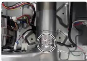
Close-up of a coiled metal pipe with wires and components, no visible text or symbols- Wrap up the joint with duct tape.
natural_image
Close-up of a mechanical assembly with visible wiring and a circular component (no text or symbols)
natural_image
Interior view of an industrial facility with machinery and a highlighted rectangular component (no visible text or symbols)- Tape on the joint between the elbow and internal duct.
Caution: Internal duct joints must be secured with tape; otherwise, they may separate and cause a safety hazard.
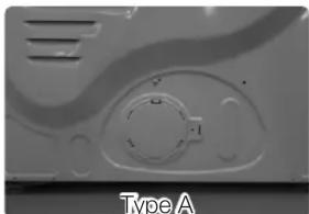
- Reinstall the exhaust duct cover on rear of cabinet.
- Insert the vent pipe cap supplied with the kit into rear exhaust hole left by old duct.
natural_image
Close-up of a metallic electronic component with internal circular features and ventilation slots (no text or symbols visible)
natural_image
Close-up of a mechanical component with a circular recess and labeled 'Type B' (no other text or symbols visible)Marque : SAMSUNG
Modèle : DV-2A
Catégorie : Sèche-linge