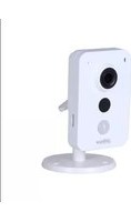
IPC-K35S - Caméra de surveillance Dahua Technology - Notice d'utilisation et mode d'emploi gratuit
Retrouvez gratuitement la notice de l'appareil IPC-K35S Dahua Technology au format PDF.


| Type de produit | Caméra de surveillance IP |
| Marque | Dahua Technology |
| Modèle | IPC-K35S |
| Dimensions (L x l x H) | Environ 70 x 65 x 155 mm |
| Poids | Environ 280 g |
| Alimentation | PoE (IEEE 802.3af) ou adaptateur 12 V DC (non inclus) |
| Consommation électrique | Max 5 W |
| Résolution maximale | 1920 x 1080 pixels (Full HD) |
| Angle de vue | Horizontal 90°, vertical 50° |
| Vision nocturne | LED infrarouge intégrées, portée jusqu'à 30 mètres |
| Fonctions principales | Détection de mouvement, enregistrement sur carte SD (jusqu'à 128 Go), flux double, compression H.265+/H.264 |
| Connectivité | Ethernet RJ45 10/100 Mbps, Wi-Fi non disponible |
| Protocoles pris en charge | TCP/IP, DHCP, DNS, ONVIF |
| Stockage | Carte microSD (non incluse) ou NVR |
| Température de fonctionnement | -30°C à +60°C |
| Indice de protection | IP67 (résistant à la poussière et à l'eau) |
| Matériau du boîtier | Métal et plastique résistant |
| Entretien et nettoyage | Nettoyer avec un chiffon doux et sec. Ne pas utiliser de produits chimiques. |
| Sécurité | Protection par mot de passe, cryptage SSL/TLS, mise à jour firmware |
| Pièces détachées et réparabilité | Aucune pièce réparable par l'utilisateur. Contacter le SAV. |
| Garantie | 2 ans (selon le revendeur) |
| Contenu de l'emballage | Caméra, support de montage, kit de visserie, guide d'installation rapide |
FOIRE AUX QUESTIONS - IPC-K35S Dahua Technology
Questions des utilisateurs sur IPC-K35S Dahua Technology
0 question sur cet appareil. Repondez a celles que vous connaissez ou posez la votre.
Poser une nouvelle question sur cet appareil
Téléchargez la notice de votre Caméra de surveillance au format PDF gratuitement ! Retrouvez votre notice IPC-K35S - Dahua Technology et reprennez votre appareil électronique en main. Sur cette page sont publiés tous les documents nécessaires à l'utilisation de votre appareil IPC-K35S de la marque Dahua Technology.
MODE D'EMPLOI IPC-K35S Dahua Technology
Dahua K Series Cube Network Camera Quick Start Guide
V 1.0.2
Zhejiang Dahua Vision Technology CO., LTD
1 Packing List

natural_image
Line drawing of a modern speaker with three circular buttons and a stand (no text or symbols)Device × 1

QSG ×1

natural_image
Technical line drawing of a mechanical tool or device with no visible text or symbols
natural_image
Simple line drawing of three screws arranged vertically (no text or symbols)2 Product Appearance

Figure 2-1
natural_image
Technical line drawing of a mechanical device with no visible text or symbolsFigure 2-2
natural_image
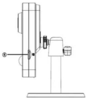
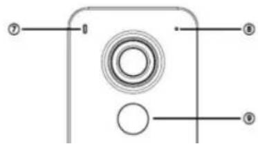
Pure mechanical part diagram with no text, numbers, or symbols| 6 | Micro SD card slot |
| 7 | Indicator light |
| 8 | Built-in MIC |
| 9 | IR LED |
| 10 | PIR (Sense IR ray, trigger alarm) |
Sheet 2-1
Note:
For reset, long press for 8 seconds and then the light off; For WPS (Wi-Fi Protected Setup), one quick press.
Please refer to the following sheet for more details about status of indicator light.
| Indicator light status | Device status |
| Red light normally on | Booting |
| Green light slow flashing | Booting completed, await wifi config, enter smart config status; |
| Green light quick flashing | Wifi smart config in progress, including WPS (Wi-Fi Protected Setup), management frame and etc. |
| Green light normally on | Wifi connection succeeded, operate normally. |
| Red and green lights flash alternately | Device upgrade |
| Red light slow flashing | Network connection failure or disconnection after network connection success. |
| Red light quick flashing | Device malfunction, fail to boot up; alarm or SD card malfunction |
Sheet 2-2
3 Operate by Easy4ip APP
Step 1
Power on the device with power adapter.
Step2
Connect your smart phone to your WiFi network. Scan the "Easy4ip APP" QR on the packing box, download and install the Easy4ip APP.
Step3
Open Easy4ip APP (downloaded from APP Store .take IOS as an example), tap "login" to login the APP, see Figure 3-1.
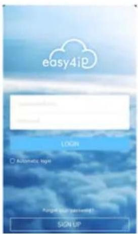

Figure 3-2
Step5
Tap “+” to add devices.


Figure 3-4
Step7
Name the camera and scan the QR code on camera.


Figure 3-6
Step8
Input the Wi-Fi password.

Figure 3-8
Note:
If you want to change the Wi-Fi signal, please reset the camera to factory default and repeat step 6-9.
Figure 3-9
4 External Alarm Input/Output Device
IPC supports external alarm device, it can externally connect to alarm input/output device via "Digital input/output".
4.1.1 Alarm Input Device (detector, sensor and so on)
Please refer to the following figure for alarm input information. See Figure 4-1.
Alarm input: When the input signal is idle or grounded, the device can collect the different statuses of the alarm input port. When the input signal is connected to the 5V or is idle, the device collects the logic "1". When the input signal is grounded, the device collects the logic "0".

flowchart
graph LR
    A["Alarm Input"] --> B["GND"]
    B --> C["IPC"]
    C --> D["Collecting"]
    D --> E["Output"]
Figure 4-1 Alarm input
4.1.2 Alarm Output Device (alarm device, beeper and so on)
Please refer to Figure 4-2 and 4-3 for alarm output information.

Mode A:
Level application. Alarm output high and low level, alarm output is OC; it needs to increase pull-up resistance externally to work normally. Max external pull-up level is 5V, max port current is 5mA. After external pull-up resistance is increased, the default of output signal is high level (external pull-up voltage), and it switches to low level when there is alarm output (when the working current is 5mA, output voltage is less than 0.8V).
Mode B:
Switch application. Alarm output is used to drive external circuit, max current is 50mA, max voltage is 12V (it can be applied together with alarm siren, acousto-optic alarm siren HC103) it is advised to add a relay if it is beyond the value.
5 Device Installation
Important:
Please make sure the installation surface can min support the 3X weight of the camera and the bracket.

natural_image
Technical line drawing of a mechanical assembly with screws and a flange (no text or symbols)Figure 5-1
Step 1
Paste the installation map on the installation surface such as wall, ceiling or the wood.
Step 2
Dig holes in the installation surface according to the installation map.
Step 3
Insert the expansion bolts from the accessories bag to the holes you just dug. If it is the wood surface you can skip to the next step.
Step 4
Note:
- This quick start guide is for reference only. Slight difference may be found in user interface.
- All the designs and software here are subject to change without prior written notice.
- All trademarks and registered trademarks mentioned are the properties of their respective owners.
- If there is any uncertainty or controversy, please refer to the final explanation of us.
- Please visit our website or contact your local service engineer for more information.
aihua
Zhejiang Dahua Vision Technology Co., Ltd
Address: No.1199 Bin'an Road, Binjiang District, Hangzhou, PRC.
Postcode: 310053
Tel: +86-571-87688883
Fax: +86-571-87688815
Email:overseas@dahuatech.com
Website: www.dahuasecurity.com
- Dahua K Series Cube Network Camera Quick Start Guide
- Product Appearance
- Note:
- Operate by Easy4ip APP
- Step 1
- Step2
- Step3
- Step5
- Step7
- Step8
- Figure 3-8
- External Alarm Input/Output Device
- Alarm Input Device (detector, sensor and so on)
- Alarm Output Device (alarm device, beeper and so on)
- Mode A:
- Mode B:
- Device Installation
- Important:
- Step 2
- Step 3
- Step 4
- aihua
Marque : Dahua Technology
Modèle : IPC-K35S
Catégorie : Caméra de surveillance