
SU-A800MK2 - Recepteur TECHNICS - Notice d'utilisation et mode d'emploi gratuit
Retrouvez gratuitement la notice de l'appareil SU-A800MK2 TECHNICS au format PDF.


| Type de produit | Récepteur stéréo intégré |
| Marque | Technics |
| Modèle | SU-A800MK2 |
| Dimensions (L x H x P) | 430 x 150 x 350 mm |
| Poids | 12 kg |
| Alimentation | 230 V ~ 50/60 Hz |
| Consommation électrique | 350 W (max) |
| Puissance de sortie | 100 W + 100 W (8 Ω, 20 Hz – 20 kHz, 0,02% DHT) |
| Réponse en fréquence | 5 Hz – 100 kHz (+0/-3 dB) |
| Sensibilité d'entrée (ligne) | 150 mV / 47 kΩ |
| Rapport signal/bruit | 100 dB (IHF-A) |
| Entrées | Phono (MM), CD, Tuner, Aux, Tape |
| Sorties | Haut-parleurs (A/B), Casque, Pré-ampli, Tape |
| Tuner intégré | FM/AM à quartz |
| Fonctions principales | Amplification, sélection de source, contrôle de tonalité, balance, tuner |
| Entretien et nettoyage | Essuyer avec un chiffon sec et doux. Ne pas utiliser de produits abrasifs. |
| Sécurité | Débrancher avant nettoyage. Ne pas exposer à l'humidité. |
| Pièces détachées et réparabilité | Contactez le service après-vente Technics pour les pièces détachées. |
| Informations générales | Notice d'utilisation disponible au format PDF sur notice-facile.com. |
FOIRE AUX QUESTIONS - SU-A800MK2 TECHNICS
Questions des utilisateurs sur SU-A800MK2 TECHNICS
0 question sur cet appareil. Repondez a celles que vous connaissez ou posez la votre.
Poser une nouvelle question sur cet appareil
Téléchargez la notice de votre Recepteur au format PDF gratuitement ! Retrouvez votre notice SU-A800MK2 - TECHNICS et reprennez votre appareil électronique en main. Sur cette page sont publiés tous les documents nécessaires à l'utilisation de votre appareil SU-A800MK2 de la marque TECHNICS.
MODE D'EMPLOI SU-A800MK2 TECHNICS
Technics
Stereo Integrated Amplifier
SU-A900MK2
SU-A800MK2
Operating Instructions

Dear Customer
Thank you for purchasing this Technics product. For optimum performance and safety, please read these instructions carefully.
These operating instructions are applicable to the SU-A900MK2 and SU-A800MK2 models. These operating instructions, however, fundamentally explain the operation of SU-A900MK2 model.
Please check and identify the supplied accessories

AC power supply cord....1 (For United (For Australia (For others) Kingdom) and N.Z.)

(VJA0733)

(RJA0036-K)

(RJA0019-2K)

Power plug adaptor (SJP5213-2).....1 (Not supplied for United Kingdom, Europe, Australia and N.Z.)


Remote control transmitter (RAK-SU129WH) ..... 1


Batteries (UM-4, "AAA", R03)....2


Contents
| Caution for AC mains lead(For United Kingdom) | 3 |
| Suggestions for safety | 4 |
| Front panel controls | 5 |
| Connections | 6 |
| Listening to Sound | 8 |
| To adjust the tone quality | 9 |
| To adjust the sound balance | 9 |
| When listening phono discs SU A900MK2 only | 9 |
| When listening through headphones | 9 |
| Recording | 10 |
| To record from compact discs, etc. | 10 |
| Tape-to-tape recording | 10 |
| Technical specifications | 11 |
| Troubleshooting guide | Back cover |
(For areas except United Kingdom, Europe, Australia and N.Z.)
CAUTION:
The AC voltage is different according to the area.
Be sure to set the proper voltage in your area before use.
(For details, please refer to the page 7.)
(For United Kingdom)
("EB" area code model only)
For your safety, please read the following text carefully.
This appliance is supplied with a moulded three pin mains plug for your safety and convenience.
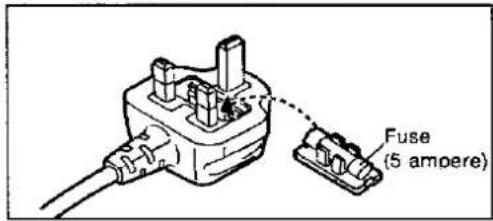
A 5-ampere fuse is fitted in this plug.
Should the fuse need to be replaced please ensure that the replacement fuse has a rating of 5-ampere and that it is approved by ASTA or BSI to BS1362. Check for the ASTA mark ☑ or the BSI mark ☑ on the body of the fuse.
If the plug contains a removable fuse cover you must ensure that it is refitted when the fuse is replaced.
If you lose the fuse cover the plug must not be used until a replacement cover is obtained.
A replacement fuse cover can be purchased from your local dealer.
CAUTION!
IF THE FITTED MOULDED PLUG IS UNSUITABLE FOR THE SOCKET OUTLET IN YOUR HOME THEN THE FUSE SHOULD BE REMOVED AND THE PLUG CUT OFF AND DISPOSED OF SAFELY.
THERE IS A DANGER OF SEVERE ELECTRICAL SHOCK IF THE CUT OFF PLUG IS INSERTED INTO ANY 13-AMPERE SOCKET.
If a new plug is to be fitted please observe the wiring code as shown below.
If in any doubt please consult a qualified electrician.
IMPORTANT
The wires in this mains lead are coloured in accordance with the following code:
Blue: Neutral
Brown: Live
As the colours of the wires in the mains lead of this appliance may not correspond with the coloured markings identifying the terminals in your plug, proceed as follows:
The wire which is coloured BLUE must be connected to the terminal in the plug which is marked with the letter N or coloured BLACK.
The wire which is coloured BROWN must be connected to the terminal in the plug which is marked with the letter L or coloured RED.
Under no circumstances should either of these wires be connected to the earth terminal of the three pin plug, marked with the letter E or the Earth Symbol 12 .
Before use
Remove the connector cover as follows.

How to replace the fuse
- Remove the fuse cover with a screwdriver.

- Replace the fuse and attach the fuse cover.
Suggestions for safety
Placement
Avoid placing the unit in areas of:
• direct sunlight
• high temperature
• high humidity
• excessive vibration
- uneven surfaces (Place the unit on a fiat level surface.)
Such conditions might damage the cabinet and/or other component parts and thereby shorten the unit's service life.
Ventilation
- Place the unit in a well ventilated position at least 10 cms away from wall surfaces etc.
- Ensure that curtains and similar materials do not obstruct the ventilation holes.
Stacking
Never place heavy items on top of the unit or the power cord.
Voltage
- It is very dangerous to use an AC power source of high voltage such as for an air conditioner.
A fire might be caused by such a connection.
• A DC power source can not be used.
Be sure to check the power source carefully, especially on a ship or other place where DC is used.
Power cord protection
- Avoid cuts, scratches or poor connection of the AC mains cord, as this may result in fire or electric shock hazard. Excessive bending, pulling or slicing of the cord should also be avoided.
- Do not pull on the cord when you are disconnecting the power, as this could cause an electric shock. Grasp the plug firmly when you disconnect the power supply.
- Never touch the plug with wet hands or a serious electric shock could result.
Foreign materials
- Ensure that no foreign objects, such as needles, coins, screwdrivers etc., accidentally fall into the unit or through the ventilation holes.
Otherwise, a serious electric shock or malfunction could occur. - Be extremely careful about spilling water or liquid on/into the unit, as a fire or electric shock could occur.
(Disconnect the power plug and contact your dealer immediately if this occurs.) - Avoid spraying insecticides onto the unit as they contain flammable gases which can be ignited.
- Insecticides, alcohol, paint thinner and similar chemicals should never be used to clean the unit as they can cause flaking or cloudiness to the cabinet finish.
Maintenance
Clean the cabinet, panel and controls with a soft cloth lightly moistened with mild detergent solution.
Do not use any type of abrasive pad, scouring powder or solvent such as alcohol or benzine.
Service
- Never attempt to repair, disassemble or reconstruct the unit if there seems to be a problem.
A serious electric shock could result if you ignore this precautionary measure. - If a problem occurs during operation (the sound is interrupted, indicators fail to illuminate, smoke is detected, etc) contact your dealer or Authorized Service Center immediately.
- Disconnect the power supply if the unit will not be used for a long time. Otherwise the operation life could be shortened.
CAUTION
Do not place a tape deck or CD player on top of this unit. Heat radiated from the top of this unit may cause damage to the tape or CD software.


| No. | Name | Ref. page |
| 1 | Power “STANDBY ⏻ /ON” switch(POWER, STANDBY ⏻ /ON) | 8 |
| Press to switch the unit from on to standby mode or vice versa. In standby mode, the unit is still consuming a small amount of power. | ||
| 2 | “STANDBY” Indicator (STANDBY) | — |
| When the unit is connected to the AC mains supply, this indicator lights up in standby mode and goes out when the unit is turned on. | ||
| 3 | Operation Indicator (OPERATION) | — |
| When the power is switched ON, this indicator illuminates after about 4 seconds when the unit is in the operating condition. | ||
| If an abnormal condition in the circuitry is detected, such as DC voltage appearing in the output or a short-circuit of the positive (+) and negative (−) wires from the speaker terminals, the protection circuit functions and this indicator will not illuminate. | ||
| 4 | Tone control button (TONE) | 9 |
| 5 | Volume control (VOLUME) | 8 |
| 6 | Tape-monitor button/Indicators(TAPE MONITOR) | 8,10 |
| No. | Name | Ref. page |
| 7 | Remote control signal receptor (SENSOR)Receives the signals from the remote control. | - |
| 8 | Headphones Jack (PHONES) | 9 |
| 9 | Speaker select buttons/indicators (SPEAKERS) | 8 |
| 10 | Tone controls (BASS/TREBLE) | 9 |
| 11 | Balance control (BALANCE) | 9 |
| 12 | Input select buttons/indicators (INPUT SELECTOR) | 8,10 |
| 13 | SU A900MK2 onlyPhono cartridge selector (PHONO SELECTOR) | 9 |
Connections
To connect to each terminal
Make connections to each component in the system by using stereo connection cables (not included).


flowchart
graph TD
    A["Tuner (not included)"] --> B["OUTPUT"]
    C["Video disc player (not included)"] --> D["AUDIO OUT"]
    E["Tape deck 1 (not included)"] --> F["REC (IN)"]
    E --> G["PLAY (OUT)"]
    H["Phone"] --> I["PHONE"]
    H --> J["TUNER"]
    H --> K["CD"]
    H --> L["AUX"]
    M["Speaker terminals See page 7."] --> N["AC IN ~"]
    O["Only for turntable with ground terminal"] --> P["OUTPUT"]
    Q["Turntable (not included)"] --> R["OUTPUT"]
    S["Compact disc player (or CD changer) (not included)"] --> T["OUTPUT"]
    U["Tape deck 2 or Digital compact cassette (DCC) (not included)"] --> V["REC (IN)"]
    U --> W["PLAY (OUT)"]
A "REMOTE CONTROL OUT" terminal
Connect the connection cable for the remote control to a Technics tape deck and/or CD player (or CD changer) which has the appropriate remote control terminal as shown at the right.
If a tape deck is not being used, the CD player (or CD changer) can be connected directly (dotted line).
Note
For a tape deck and/or CD player (or CD changer) with a remote control sensor, this connection is not necessary.

flowchart
graph TD
    A["This unit"] --> B["Tape deck (not included)"]
    A --> C["Compact disc player (not included)"]
    B --> D["Remote CONTROL OUT"]
    C --> E["Remote CONTROL OUT"]
    D --> F["Connection cable for remote control (Included with tape deck)"]
    E --> G["Connection cable for remote control (Included with compact disc player)"]
To connect the speakers
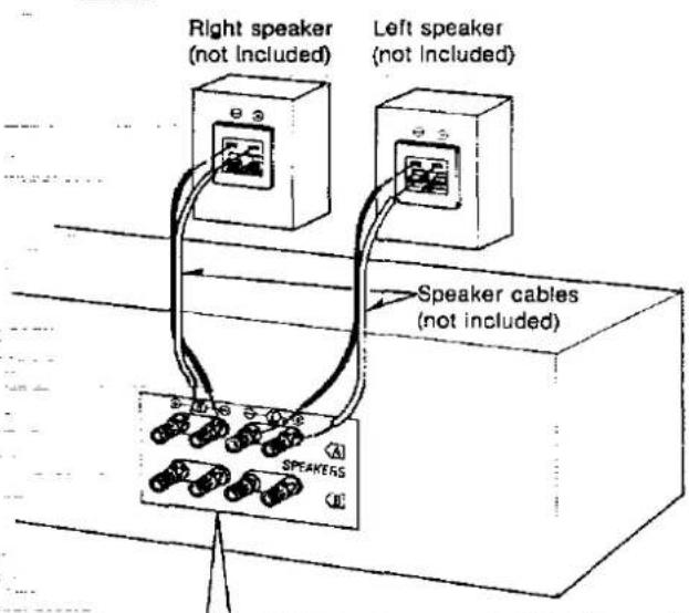
① Strip off the outer covering, and twist the center conductor.
② Turn completely to the left.
③ Insert the wire and turn completely to the right. Pull the cord to assure a proper connection.
Note Be sure to only connect positive (+) cords to positive (+) terminals, and negative (−) cords to negative (−) terminals.
Note
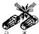
To prevent damage to circuitry, never short-circuit the positive (+) and negative (−) speaker wires.


■ "B" terminals
For connection to a second pair of speakers.
■ Speaker Impedance
- When only the "A" or only the "B" terminals are used: 4–16 ohms
- When both the "A" and the "B" terminals are used simultaneously: 8–16 ohms
About the cooling fan
The cooling fan operates at high power output levels only.
SU-A800MK2 only
There is no cooling fan for some countries.
To connect the AC power supply cord
FOR UNITED KINGDOM ONLY BE SURE TO READ THE CAUTION FOR THE AC POWER SUPPLY CORD ON PAGE 3 BEFORE CONNECTING THE AC POWER SUPPLY CORD.
For areas except United Kingdom, Europe, Australia and N.Z. SU.A900MK2 only
Be sure to set the voltage selector to "110 V-127 V" or "220 V-240 V" according to the area in which the unit will be used. [Use a minus (-) screwdriver]

Note
Note that this unit will be seriously damaged if this setting is not made correctly.

Note
The configuration of the AC power supply cord differs according to area.
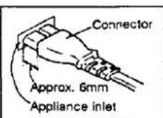
(For areas except Australia and N.Z.) Insertion of Connector
Even when the connector is perfectly inserted, depending on the type of inlet used, the front part of the connector may jut out as shown in the drawing.
However there is no problem using the unit.
-Not supplied for United Kingdom, Europe, Australia and N.Z.
If the power plug will not fit your socket, use the power plug adaptor (included).

Listening to Sound
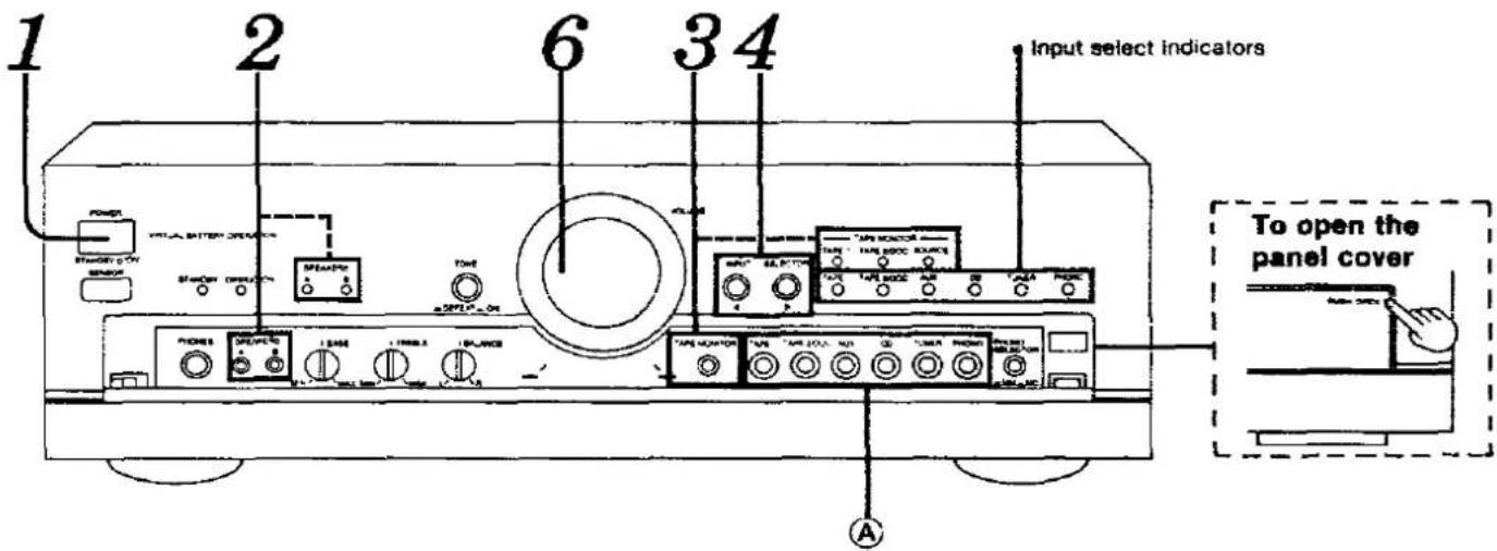
Before operation, set VOLUME to the "MIN" position


Press POWER to switch on the power.


Press A and/or B to select the speaker system(s) to be used.
A and B refer to the speaker terminals at the rear of the unit.
The corresponding indicator above will illuminate to indicate which speaker system is selected.
A: Sound can be heard from the speakers connected to the "A" terminals.
B: Sound can be heard from the speakers connected to the "B" terminals.
A and B: Sound can be heard simultaneously from the speakers connected to the "A" terminals and the "B" terminals.
off: No sound will be heard from the speakers. (Both indicators will turn off.)

Press ◀ or ▶ to select the sound source.
: Each time the button is pressed, the illuminated position of the input select indicator will shift one position to the left.
: Each time the button is pressed, the illuminated position of the input select indicator will shift one position to the right.
To directly select the input source
The desired input source can be selected directly by using the input select buttons ( Ⓐ ) located inside the panel.
TAPE 1: Set to this position to listen to equipment connected to the "TAPE 1" terminals.
"TAPE 2/DCC: Set to this position to listen to equipment connected to the "TAPE 2/DCC" terminals.
AUX: Set to this position to listen to equipment connected to the "AUX" terminals.
CD: Set to this position to listen to compact discs. TUNER: Set to this position to listen to radio broadcasts.
PHONO: Set to this position to listen to phono discs. For SU-AD00MK2
Then, set the phono cartridge selector to the position which corresponds to the type
PHONE SELECTION on page 9)

TAPE MONITOR

Press TAPE MONITOR so that the "SOURCE" indicator illuminates.
Note
When a graphic equalizer is connected to the "TAPE 1" or "TAPE 2/DCC" terminals, press the button so that the "TAPE 1" or "TAPE 2/DCC" indicator illuminates.

Start the desired source.
(Refer to the appropriate operating instructions for details.)

VOLUME Turn VOLUME to adjust the volume level.
After listening is finished
Be sure to reduce the volume level, and switch the power to the standby condition by pressing POWER.

To adjust the tone quality

Set TONE to the "ON" position. If set to the "DEFEAT" position, tone controls have no effect.


Turn BASS to adjust the low-frequency sound.

Turn TREBLE to adjust the high-frequency sound.
To adjust the sound balance

Turn BALANCE to adjust the left/right sound balance.
When listening phono discs
SU.A900MK2 only

Select the cartridge type.
MM:
Set to this position when using a moving-magnet type cartridge or high-output moving-coil cartridge (1 mV or more).
MC:
Set to this position when using a moving-coil type cartridge.
When listening through headphones
Use VOLUME to reduce the volume level, and connect the headphones.
If sound from speakers is not wanted, press SPEAKERS (A) and/or (B) to turn off the speaker select indicators.
Note
Avoid listening for prolonged periods of time to prevent hearing damage.
Recording
To record from compact discs, etc.
It is possible to record from units which are connected to the rear "AUX", "CD", "TUNER" or "PHONO" terminals to cassette tape decks or DCC decks which are connected to the "TAPE 1" or "TAPE 2/DCC" terminals.
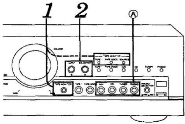
Before recording, prepare the tape deck or DCC for recording (recording level adjustment, etc.). See the tape deck's or DCC's operating instructions for details.

Press TAPE MONITOR so that the "SOURCE" indicator illuminates.

Select the program source to be recorded.
AUX: To record from equipment connected to the "AUX" terminals.
CD: To record from compact discs.
TUNER: To record from radio broadcasts.
PHONO: To record from phono discs.

Begin recording.
Follow your tape deck's or DCC's operating instructions.

Begin the source to be recorded.
Tape-to-tape recording
It is possible to record from tape deck 1 (the cassette tape deck which is connected to the "TAPE 1" terminals) to tape deck 2 (the cassette tape deck or DCC_deck which is connected to the "TAPE 2/DCC" terminals) and vice versa.

Preparation
- Before recording, prepare the tape deck or DCC for recording (recording level adjustment, etc.).
See the tape deck's of DCC's operating instructions for details.
- Load tapes which have been advanced to the end of the leader tape into both decks.
To record from tape deck 2 to 1

Press TAPE MONITOR so that the "SOURCE" Indicator Illuminates.

Press ◀ or ▶ to select "TAPE 2/DCC".

Begin tape deck 1 for recording and tape deck 2 for playback.
To record from tape deck 1 to 2

Press TAPE MONITOR so that the "SOURCE" indicator illuminates.

Press ◀ or ▶ to select "TAPE 1".

Begin tape deck 2 for recording and tape deck 1 for playback.
■ To directly select the source for recording
The desired source can be selected directly by using the input select buttons (A,B) located inside the panel.
■ To check the sound recorded while recording is being made
If a cassette tape deck with 3 heads is connected to the "TAPE 1" or "TAPE 2/DCC" terminals, it is possible to check the sound being recorded onto the tape.
TAPE MONITOR

Press TAPE MONITOR to select the deck (tape deck 1 or 2) and set the monitor switch on the tape deck to "TAPE".
TAPE 1: when recording on tape deck 1 TAPE 2/DCC: when recording on tape deck 2
clinical specifications (DIN 45 500)
20 Hz-20 kHz continuous power output
| both channels driven | [SU-A900MK2] : 2 × 90 W (8 Ω) |
| [SU-A800MK2] : 2 × 55 W (8 Ω) |
1 kHz continuous power output
both channels driven (THD: 1%)
| [SU-A900MK2] : 2 × 100 W (8 Ω) |
| 2 × 140 W (4 Ω) |
| [SU-A800MK2] : 2 × 70 W (8 Ω) |
| 2 × 100 W (4 Ω) |
63 Hz-12.5 kHz continuous power output
both channels driven (THD: 0.7%)
| [SU-A900MK2] : 2 × 90 W (8 Ω) |
| 2 × 125 W (4 Ω) |
| [SU-A800MK2] : 2 × 65 W (8 Ω) |
| 2 × 85 W (4 Ω) |
Total harmonic distortion
| rated power at 20 Hz-20 kHz | 0.01% (8 Ω) |
Intermodulation distortion (50 Hz: 7 kHz=4:1, SMPTE)
| rated power | 0.007% (8 Ω) |
| residual hum and noise | 1 mV |
| amping factor | 60 (8 Ω) |
| 30 (4 Ω) |
Headphones output level/impedance
Load impedance
| A or B | 4-16 Ω |
| A and B | 8-16 Ω |
Input sensitivity/impedance
| PHONO MM | 2.5 mV/47 kΩ |
| PHONO MC [SU-A900MK2 only] | 170 μV/220 Ω |
| TUNER, CD, AUX, TAPE 1, TAPE 2/DCC | 150 mV/22 kΩ |
Phono maximum input voltage (1 kHz, RMS)
| MM | 160 mV (IHF '66) |
| MC [SU-A900MK2 only] | 12 mV (IHF '66) |
S/N (rated power, 4 Ω)
| PHONO MM | 78 dB (85 dB, IHF '66) |
PHONO MC [SU-A900MK2 only]
| 64 dB (S=250 μV, 66 dB, IHF '66) |
TUNER, CD, AUX, TAPE 1, TAPE 2/DCC
| 91 dB (100 dB, !HF '66) |
S/N at -26 dB power (4 Ω)
| PHONO MM | 68 dB |
| PHONO MC [SU-A800MK2 only] | 63 dB |
| TUNER, CD, AUX, TAPE 1, TAPE 2/DCC | 70 dB |
S/N at 50 mW power (4 Ω)
| PHONO MM | 64 dB |
| PHONO MC [SU-A900MK2 only] | 60 dB |
| TUNER, CD, AUX, TAPE 1, TAPE 2/DCC | 64 dB |
Frequency response
| PHONO MM | RIAA standard curve ±0.8 dB(30 Hz-15 kHz) |
TUNER, CD, AUX, TAPE 1, TAPE 2/DCC
| 3 Hz-80 kHz (+0,-3 dB) |
| +0 dB, -0.3 dB (20 Hz-20 kHz) |
Tone controls
| BASS | 50 Hz, +10 to -10 dB |
| TREBLE | 20 kHz, +10 to -10 dB |
Output voltage
| TAPE 1, TAPE 2/DCC REC OUT | 150 mV |
| channel balance (AUX 250 Hz-8.3 kHz) | ±1 dB |
| channel separation (AUX 1 kHz) | 50 dB |
GENERAL
Power consumption [SU-A900MK2] : 315 W
[SU-AB00MK2] : 230 W
Power supply
| For Europe | AC 50 Hz/60 Hz, 230 V |
| For United Kingdom, Australia and N.Z. | |
AC 50 Hz/60 Hz, 230 V-240 V
| For others | AC 50 Hz/60 Hz, 110 V-127 V/220 V-240 V |
Dimensions (W × H × D)
| Weight | [SU-A900MK2] : 9.4 kg |
| [SU-A800MK2] : 8.6 kg |
Notes:
- Specifications are subject to change without notice. Weight and dimensions are approximate.
- Total harmonic distortion is measured by the digital spectrum analyzer.
- For areas except Europe
The specification values given have been measured while using a 240 V power supply.
For United Kingdom only
This apparatus was produced to BS 800.
Troubleshooting Guide
Before requesting service for this unit, check the chart below for a possible cause of the problem you are experiencing. Some simple checks or a minor adjustment on your part may eliminate the problem and restore proper operation.
If you are in doubt about some of the check points, or if the remedies indicated in the chart do not solve the problem, refer to the directory of Authorized Service Centers (enclosed with this unit) to locate a convenient service center, or consult your Technics dealer for instructions.
| Problem | Probable cause(s) | Suggested remedy |
| During phono disc play SU-A900MK2 only | ||
| The sound lacks clarity and volume. | The phono cartridge selector is incorrectly set to the "MM" position when a moving-coil type cartridge is being used. | • Set it to the "MC" position. |
| The high-frequency range cannot be clearly heard. | The phono cartridge selector is incorrectly set to the "MC" position when a moving-magnet type cartridge is being used. | • Set it to the "MM" position. |
| Problems noted at all times | ||
| No sound is heard when the power is switched ON. | The power cord plug is not completely inserted. | · Confirm that the power cord plug is connected completely. |
| Connections to the speakers, etc. are incomplete or incorrect. | · Check to be sure that all connection wires are correctly connected. | |
| The Input selector setting is Incorrect. | · Check to be sure that the selection of the desired sound source is made correctly. | |
| The speaker selector is set incorrectly. | · Set it to the correct position. | |
| The tape monitor function is on.(TAPE 1 or TAPE 2/DCC indicator is illuminated) | · When listening to a source other than a tape or DCC, press TAPE MONITOR so that the "SOURCE" Indicator Illuminates. | |
| When listening to stereo sound, the sound lacks depth (i.e. thin bass, tinny sound). | One of the speakers is connected out of phase [(+)→(-), (-)→(+)]. | · Reconnect the speakers maintaining proper polarity [i.e., (+)→(+), (-)→(-)]. |
| When listening to stereo sound, the left and right sounds are reversed. | The left and right speaker connections, source connections, or graphic equalizer connections are reversed. | · Check all connections and correct them if necessary. |
| A low-pitched noise ("hum" or "buzz") is heard. | The power cord or a fluorescent light, etc., is near the connection wires. | · Try separating this unit as far as possible from the electric appliance. |
| Sound is not heard from one of the speakers. | The speaker wires are disconnected. | · Check and correct the connections of the speaker wires. |
| The balance control is set too far to one side. | · Set so that sounds are heard at the center, between the speakers. | |
| Sound stops during a performance, or no sound is heard when the power is switched ON. | The protection circuitry has functioned because the positive and negative speaker connection wires are "shorted", speakers with an impedance less than the indicated rated impedance of the amplifier are used, or DC voltage appears in the output, causing the protection circuitry to function. | · Switch OFF the power, and, after determining and correcting the cause, switch ON the power once again.· Use the speakers of the proper impedance rating. |

Matsushita Electric Industrial Co., Ltd.
Central P.O. Box 288, Osaka 530-91, Japan
- Technics
- Stereo Integrated Amplifier
- SU-A900MK2
- SU-A800MK2
- Dear Customer
- Contents
- CAUTION:
- (For United Kingdom)
- ("EB" area code model only)
- CAUTION!
- IMPORTANT
- Before use
- How to replace the fuse
- Suggestions for safety
- Placement
- Ventilation
- Stacking
- Voltage
- Power cord protection
- Foreign materials
- Maintenance
- Service
- CAUTION
- Connections
- To connect to each terminal
- A "REMOTE CONTROL OUT" terminal
- Note
- To connect the speakers
- ■ "B" terminals
- ■ Speaker Impedance
- About the cooling fan
- SU-A800MK2 only
- To connect the AC power supply cord
- For areas except United Kingdom, Europe, Australia and N.Z. SU.A900MK2 only
- (For areas except Australia and N.Z.) Insertion of Connector
- -Not supplied for United Kingdom, Europe, Australia and N.Z.
- Listening to Sound
- To adjust the tone quality
- To adjust the sound balance
- When listening phono discs
- SU.A900MK2 only
- Select the cartridge type.
- When listening through headphones
- Recording
- To record from compact discs, etc.
- Tape-to-tape recording
- Preparation
- To record from tape deck 2 to 1
- To record from tape deck 1 to 2
- ■ To directly select the source for recording
- ■ To check the sound recorded while recording is being made
- clinical specifications (DIN 45 500)
- GENERAL
- Notes:
- For United Kingdom only
- Troubleshooting Guide
Marque : TECHNICS
Modèle : SU-A800MK2
Catégorie : Recepteur