
AG-6040E - Caméra de surveillance PANASONIC - Notice d'utilisation et mode d'emploi gratuit
Retrouvez gratuitement la notice de l'appareil AG-6040E PANASONIC au format PDF.


| Type de produit | Caméra de surveillance analogique |
| Marque | Panasonic |
| Modèle | AG-6040E |
| Dimensions (L x H x P) | 68 mm x 58 mm x 115 mm |
| Poids | 350 g |
| Alimentation | 12 V CC / 24 V CA |
| Consommation électrique | 4,5 W |
| Capteur | CCD 1/3" |
| Résolution | 570 lignes TV (couleur) |
| Angle de vue | Champ de vision horizontal 70° |
| Sortie vidéo | Composite 1 Vpp, 75 ohms |
| Fonctions principales | Vision nocturne infrarouge, balance des blancs automatique, compensation de contre-jour |
| Entretien et nettoyage | Nettoyer l'objectif avec un chiffon doux sec ; éviter les solvants |
| Sécurité | Utiliser une source d'alimentation stable ; ne pas exposer à l'humidité |
| Pièces détachées et réparabilité | Disponibles chez revendeurs agréés Panasonic |
| Informations générales | Notice d'utilisation téléchargeable au format PDF sur notice-facile.com |
FOIRE AUX QUESTIONS - AG-6040E PANASONIC
Questions des utilisateurs sur AG-6040E PANASONIC
0 question sur cet appareil. Repondez a celles que vous connaissez ou posez la votre.
Poser une nouvelle question sur cet appareil
Téléchargez la notice de votre Caméra de surveillance au format PDF gratuitement ! Retrouvez votre notice AG-6040E - PANASONIC et reprennez votre appareil électronique en main. Sur cette page sont publiés tous les documents nécessaires à l'utilisation de votre appareil AG-6040E de la marque PANASONIC.
MODE D'EMPLOI AG-6040E PANASONIC
Operating Instructions
SVHS
VHS
PAL
VHS
625
PAL
Model AG-6730/6040 E
- Model AG-6730 is an S-VHS type of video recorder.
- Model AG-6040 is a VHS type of video recorder.
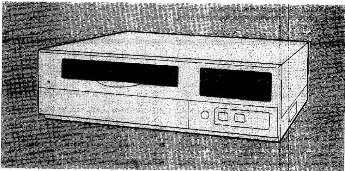
natural_image
Illustration of a vintage computer or electronic device with two screens and control buttons (no visible text or symbols)Time Lapse Recorder
Before attempting to use this unit, read through these instructions and follow the proper operating procedures. Keep these instructions in a safe place for future reference.
- A tape recorded using the S-VHS System cannot be used on a model which is designed to accommodate only the VHS System.
Caution for AC Mains Lead
FOR YOUR SAFETY PLEASE READ THE FOLLOWING TEXT CAREFULLY.
This product is equipped with 2 types of AC mains cable. One is for continental Europe, etc and the other one is only for U.K.
Appropriate mains cable must be used in each local area, since the other type of mains cable is not suitable.
FOR CONTINENTAL EUROPE, ETC
Not to be used in the U.K.

natural_image
Line drawing of a cord with a plug and cable (no text or symbols)FOR U.K. ONLY
If the plug supplied is not suitable for your socket outlet, it should be cut off and appropriate one fitted.

FOR U.K. ONLY
This appliance is supplied with a moulded three pin mains plug for your safety and convenience.
A 13 amp fuse is fitted in this plug.
Should the fuse need to be replaced please ensure that the replacement fuse has a rating of 13 amps and that it is approved by ASTA or BSI to BS1362.
Check for the ASTA mark 📄 or the BSI mark 💙 on the body of the fuse.
If the plug contains a removable fuse cover you must ensure that it is refitted when the fuse is replaced.
If you lose the fuse cover the plug must not be used until a replacement cover is obtained.
A replacement fuse cover can be purchased from your local Panasonic Dealer.
IF THE FITTED MOULDED PLUG IS UNSUITABLE FOR THE SOCKET OUTLET IN YOUR HOME THEN THE FUSE SHOULD BE REMOVED AND THE PLUG CUT OFF AND DISPOSED OF SAFELY.
THERE IS A DANGER OF SEVERE ELECTRICAL SHOCK IF THE CUT OFF PLUG IS INSERTED INTO ANY 13 AMP SOCKET.
If a new plug is to be fitted please observe the wiring code as shown below.
If in any doubt please consult a qualified electrician.
WARNING: THIS APPLIANCE MUST BE EARTHED.
IMPORTANT: The wires in this mains lead are coloured in accordance with the following code:
Green-and-Yellow: Earth
Blue: Neutral
Brown: Live
As the colours of the wires in the mains lead of this appliance may not correspond with the coloured markings identifying the terminals in your plug, proceed as follows:
- The wire which is coloured GREEN-AND-YELLOW must be connected to the terminal in the plug which is marked with the letter E or by the Earth symbol 12 or coloured GREEN or GREEN-AND-YELLOW.
- The wire which is coloured BLUE must be connected to the terminal in the plug which is marked with the letter N or coloured BLACK.
- The wire which is coloured BROWN must be connected to the terminal in the plug which is marked with the letter L or coloured RED.
How to replace the fuse
- Open the fuse compartment with a screwdriver.
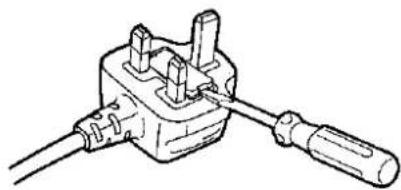
natural_image
Line drawing of a mechanical component with two screws and a base (no text or symbols)- Replace the fuse.

IMPORTANT
"Unauthorized recording of copyrighted television programmes, films, video tapes and other materials may infringe on the right of copyright owners and be contrary to copyright laws."
■ THIS APPARATUS MUST BE EARTHED.
To ensure safe operation the three-pin lead supplied must be connected only into a standard three-pin power point which is effectively earthed through the normal household wiring.
Extension cords used with the equipment must be three-core and be correctly wired to provide connection to earth. Wrongly wired extension cords are a major cause of fatalities.
The fact that the equipment operates satisfactorily does not imply that the power point is earthed and that the installation is completely safe. For your safety, if in any doubt about the effective earthing of the power point, consult a qualified electrician.
■ DO NOT REMOVE PANEL COVER BY UNSCREWING.
To reduce the risk of electric shock, do not remove cover. No user serviceable parts inside. Refer servicing to qualified service personnel.
■ If the unit is not going to be used for length of time, turn the power OFF and disconnect the power plug from the AC outlet.
CAUTION:
TO REDUCE THE RISK OF FIRE OR SHOCK HAZARD AND ANNOYING INTERFERENCE, USE THE RECOMMENDED ACCESSORIES ONLY.
WARNING:
TO REDUCE THE RISK OF FIRE OR SHOCK HAZARD, DO NOT EXPOSE THIS EQUIPMENT TO RAIN OR MOISTURE.
Caution:
Do not install or place this unit in a bookcase, built in cabinet or in another confined space in order to keep well ventilated condition.
Ensure that curtains and any other materials do not obstruct the ventilation condition to prevent risk of electric shock or fire hazard due to overheating.
■ Do not insert fingers or any other objects into the video cassette holder.
■ Avoid operating or leaving the unit near strong magnetic fields. Be especially careful of large audio speakers.
■ Avoid operating or storing the unit in an excessively hot, cold, or damp environment as this may result in damage both to the recorder and to the tape.
■ Do not spray any cleaner or wax directly on the unit.
■ If the unit is not going to be used for a length of time, protect it from dirt and dust.
■ Do not leave a cassette in the recorder when not in use.
■ Do not block the ventilation slots on the top of the unit.
■ Use this horizontally and do not place anything on the top panel.
■ Cassette tape can be used only for one-side, one direction recording. Two-way or two-track recordings cannot be made.
■ Cassette tape can be used for either Colour or Black & White recording.
■ Do not attempt to disassemble the recorder.
There are no user serviceable parts inside.
■ If any liquid spills inside the recorder, have the recorder examined for possible damage.
■ Refer any needed servicing to authorized service personnel.
is the safety information.
Table of Contents
| Time Lapse Recorder | Features......4System Configuration......6Controls and Their Functions......8Description of Displays......10 |
| For First-Time Operators | Operation Map......12Basic First Steps For Operation......14Recording......18Alarm Recording......20Internal Timer Recording......24External Timer Recording......28Playback......30Search Operations......32Time & Date Setting......34Operating Precautions......36 |
| Menu Screens | Outline of Menu Screens......38Menu Screen 1 (Screen Display Settings)......40Menu Screen 2 (VTR Mode Settings 1)......42Menu Screen 3 (VTR Mode Settings 2)......44Menu Screen 4 (Alarm Recording Mode Settings)......46Menu Screen 5 (1-Shot Recording Mode Settings)......48Menu Screen 6 (Internal Timer Recording Mode Settings) ..50Only When Optional RS-232C Interface Board Is MountedMenu Screen 7 (RS-232C Parameter Settings)......52Menu Screen 8 (Time Code Settings)......54 |
| Checkpoints for Menu Setting......56 | |
| Helpful Functions | Series Recording (Continuous Recording With Several VTRs)......581-Shot Recording......60Automatic Time Setting......64Other Functions......66 |
| Connections | Equipment Connections......68Terminal Connections......70Terminal Signal Levels......74 |
| Precautions For Use | Dew ("d" Display)......76Error Codes......77Safety Precautions......78Handling Precautions......79Daily Inspections/Regular Inspections......80Optional Accessories......82Troubleshooting (Q&A)......84 |
| Specifications......86 |
Features
Highly reliable IQ (intelligent quest) mechanism
■ 2 reel motors
Each of the two reels for taking up and advancing the tape has its own motor.
■ New brush-less motors
Newly developed and extremely durable brush-less motors are used for the direct drive (DD) motors.
■ Large-diameter impedance rollers (model AG-6730 only)
These large-diameter rollers made of pure brass have a large mass to keep the tape tension constant.
■ 16-bit digital servo system
This controls the tape transport system to a high degree of accuracy and stabilizes tape transport. It improves the recording and playback accuracy and enhances the picture quality overall.
S-VHS system with high picture quality
(model AG-6730 only)
The adoption of the S-VHS system enables high-definition pictures with a horizontal resolution of over 400 lines to be achieved.
Horizontal resolution of 400 lines

■ Conditions for achieving a horizontal resolution of over 400 lines

flowchart
graph LR
    A["Camera"] --> B["Tape"]
    B --> C["Recording/playback"]
    C --> D["Monitor"]

    A -->|Camera with a horizontal resolution of over 400 lines| A1
    B -->|Using a Panasonic S-VHS tape| B1
    C -->|Recording/playback in the S-VHS mode monitor| C1
    D -->|Monitor with a horizontal resolution of over 400 lines| D1
Multiple-function recording modes
■ Wide variety of recording time modes enabling long-duration recording
• 3-, L12-, L24-, 24-, 48-, 72-, 84-, 120-, 180-, 240- and 480-hour recording modes
• 1-shot recording mode
■ Internal timer recording modes for achieving the automation and labour-saving of monitoring functions
■ External timer recording modes for even more reliable operation
■ Alarm recording mode which, when an alarm signal is input, switches the VTR to an hour mode enabling high-fidelity pictures to be recorded
Coupled to emergency bell and alarm
• Corners where a cash dispenser or automatic teller machine is installed
• Convenience stores, etc.
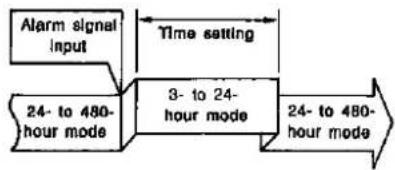
flowchart
graph LR
    A["Alarm signal input"] --> B["Time setting"]
    B --> C["24- to 480-hour mode"]
    C --> D["3- to 24-hour mode"]
    D --> E["24- to 480-hour mode"]
■ Sensor recording mode which starts recording when an alarm signal is input even when the VTR is shut down or when the power is OFF (emergency recording)
- Sensor recording is possible even when the VTR is standing by in the internal timer recording mode.

flowchart
graph TD
    A["Alarm signal Input"] --> B["Standing by (OFF)"]
    B --> C["Time setting"]
    C --> D["3- to 24-hour mode"]
    D --> E["Shutdown (OFF)"]
(it is also possible to prevent the time mode from being changed during alarm recording or sensor recording.)
Other Features
■ The cleaning roller automatically cleans the head cylinder each time a tape is loaded.
■ When the optional RS-232C interface adaptor AG-IA670 is mounted, a personal computer can be used to control the VTR.
Also, VITC time codes can be recorded (see page 83).

flowchart
graph TD
    A["Personal computer"] -->|RS-232C communication is possible when the optional RS-232C interface adaptor AG-IA670 is mounted.| B["Sequential switcher"]
    B --> C["TV cameras"]
    C --> D["Video cameras providing gen-lock are recommended when configuring a system with the sequential switcher."]
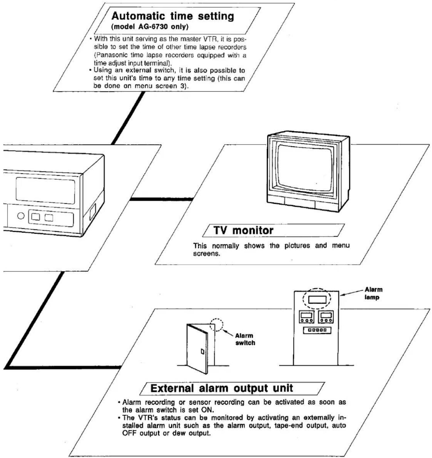
flowchart
graph TD
    A["Automatic time setting (model AG-6730 only)"] --> B["With this unit serving as the master VTR, it is possible to set the time of other time lapse recorders (Panasonic time lapse recorders equipped with a time adjust input terminal). Using an external switch, it is also possible to set this unit's time to any time setting (this can be done on menu screen 3)."]
    B --> C["TV monitor"]
    C --> D["This normally shows the pictures and menu screens."]
    C --> E["External alarm output unit"]
    E --> F["Alarm recording or sensor recording can be activated as soon as the alarm switch is set ON. The VTR's status can be monitored by activating an externally installed alarm unit such as the alarm output, tape-end output, auto OFF output or dew output."]
    E --> G["Alarm lamp"]

Front Panel
① VTR Lamp
This lights when the power is turned on.
② Cassette Holder (see page 14)
③ Display Section (see page 10)
④ EJECT Button (see page 14)
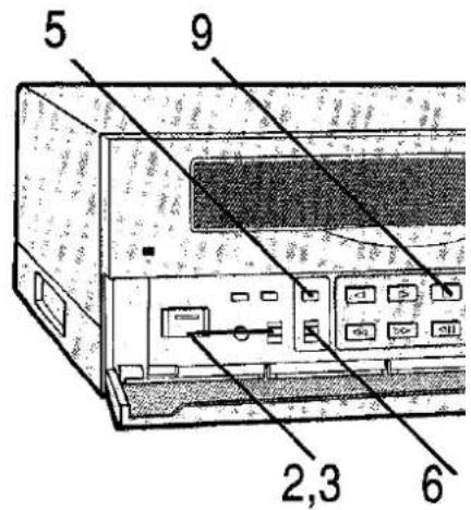
⑤ REC REVIEW Button (see page 16)
When this is pressed while recording is in progress, the recording can be monitored.
⑥ REC Button (see page 18)
Sub Panel
⑦ VTR Button
For Swedish and Danish Customers
- Aven om denna omkopplare är i "OFF"-läge, gar fortfarande en del av apparaten nätspänning.
- Selv om denne omskifter er i "OFF" stilling, tiløres en del af apparatet stadig strøm.
⑧ TRACKING Controls (see page 31) Used to adjust the tracking.
⑨ REC MODE Button (see page 17) Used to select the recording mode.
⑩ REV PLAY Button (see page 30)
⑪ PLAY Button (see page 30)
⑫ STOP Button (see page 14)
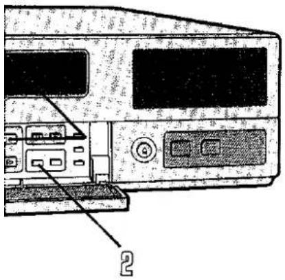
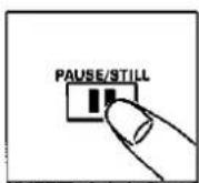
13 PAUSE/ STILL Button (see page 15) Used for temporarily stopping recording or for still-picture playback.
TIME MODE Buttons (see page 17) Used to select the time mode.
Front panel

flowchart
graph TD
    A["Device 1"] --> B["Control Panel"]
    B --> C{Switch}
    C -->|Yes| D["Switch 1"]
    C -->|No| E["Switch 2"]
    D --> F["Control Panel 7"]
    E --> G["Control Panel 8"]
    F --> H["Program"]
    G --> I["Program"]
    H --> J["TRACKING"]
    I --> K["PROGRAM"]
    J --> L["REC MODE"]
    K --> M["REC MODE"]
    L --> N["REC MODE"]
    M --> O["REC MODE"]
    N --> P["REC MODE"]
    O --> Q["REV PLAY"]
    P --> R["REV PLAY"]
    Q --> S["SNP"]
    R --> T["SNPS"]
    S --> U["STOP"]
    T --> V["FUSC"]
    U --> W["FUSC"]
    V --> X["FUSC"]
    W --> Y["FUSC"]
    X --> Z["FUSC"]
    Y --> AA["FUSC"]
    Z --> AB["FUSC"]
    style A fill:#f9f,stroke:#333
    style B fill:#ccf,stroke:#333
    style C fill:#cfc,stroke:#333
    style D fill:#fcc,stroke:#333
    style E fill:#cff,stroke:#333
    style F fill:#ffc,stroke:#333
    style G fill:#ffc,stroke:#333
    style H fill:#cfc,stroke:#333
    style I fill:#cfc,stroke:#333
    style J fill:#cfc,stroke:#333
    style K fill:#cfc,stroke:#333
    style L fill:#cfc,stroke:#333
    style M fill:#cfc,stroke:#333
    style N fill:#cfc,stroke:#333
    style O fill:#cfc,stroke:#333
    style P fill:#cfc,stroke:#333
    style Q fill:#cfc,stroke:#333
    style R fill:#cfc,stroke:#333
    style S fill:#cfc,stroke:#333
    style T fill:#cfc,stroke:#333
    style U fill:#cfc,stroke:#333
    style V fill:#cfc,stroke:#333
    style W fill:#cfc,stroke:#333
    style X fill:#cfc,stroke:#333
    style Y fill:#cfc,stroke:#333
    style Z fill:#cfc,stroke:#333
Expanded view of sub panel


flowchart
graph TD
    A["PLAY"] --> B["STOP"]
    B --> C["PAUSB/STILL"]
    C --> D["TIME MODE"]
    D --> E["ALARM"]
    E --> F["RESET"]
    F --> G["TIME/COUNTER"]
    F --> H["HCUR/METER"]
    G --> I["15"]
    H --> J["16"]
    I --> K["22"]
    J --> L["23"]
    K --> M["24"]
    L --> N["25"]
    M --> O["26"]
    N --> P["27"]
    O --> Q["28"]
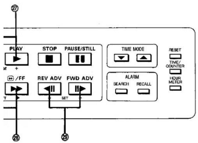
Sub Panel
⑮ RESET Button (see pages 17, 23, 44)
Used to reset the tape counter.
16 TIME/COUNTER Display Selector Button (see page 17)
Used to switch between the time display and tape counter display.
⑰ HOUR METER Button
(see page 81)
Press this to display the total time that the VTR has been used (the cylinder has turned).
⑱ PICTURE Control (see page 31)
Used to adjust the playback picture quality.
19 PROGRAM Switch (see pages 16, 34, 39)
Used to display the menus and set the time/date.
⑳ REC LOCK Switch (see page 17)
Used to set the recording lock mode.
②1 REW Button (see pages 15, 32)
② FF Button (see pages 15, 32)
②3 FIELD ADV (REV) Button
(see page 15)
② FIELD ADV (FWD) Button (see page 15)
⑲ ALARM SEARCH Button
(see page 33)
Used to set the alarm search function.
② ALARM RECALL Button
(see page 23)
Used to display the alarm memory data on the monitor screen.
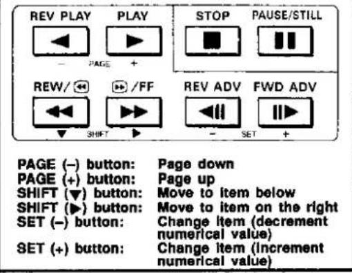
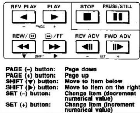
②7 PAGE Buttons (see page 39)
Used to move the menu screen up or down by one page.
②8 SHIFT Buttons (see page 39)
Used to select items on the menu screen.
⑲ SET Buttons (see page 39)
Used to select the setting value.



Various information relating to the VTR appears on the large-sized display on the front panel.

Appears during playback/recording in the S-VHS mode. (Model AG-6730 only)

Lights up during recording.

Indicates the hour mode.
Indicates the recording mode. No display: Regular mode EXTERNAL TIMER: External timer recording mode INTERNAL TIMER: Internal timer recording mode (when this mode is selected, the power is turned off).

Appears when the alarm recording mode is set. It appears when "MODE" on menu screen 4 is set to any of the options except "OFF." (See page 46)

Appears when a cassette is inserted. After the recording review, this flashes when an error occurs. (See page 77)

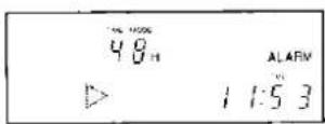
Indicates the VTR's operating mode. ▷ : Playback ◀ : Reverse playback REC ▷ : Recording, monitoring of recording REC □□ : Recording pause □□ : Still-picture, frame advance ▶▶ : Fast forward, search forward ◀◀ : Rewind, search reverse

Appears when the alarm search mode is established. (see page 33)

Indicates the time/date or tape counter value.

Indicates an error code when an error occurs. (See page 77)
For First-Time Operators
| Overall operational flowRecording | Operation Map......12Basic First Steps For Operation......14 |
| Recording......18Alarm Recording......20Sensor (emergency) recording mode......23Alarm memory recall function......23Internal Timer Recording......24External Timer Recording......28 | |
| Playback | Playback......30Tracking adjustments......31Vertical Lock Adjustment (model AG-6040 only)......31Picture quality adjustments......31Time modes......31Search Operations......32Search forward/search reverse......32Alarm search......33 |
| Time settingPrecautions | Time & Date Setting......34 |
| Operating Precautions......36 |

The sequence of steps to be taken from connecting the VTR to playback is described on these pages.
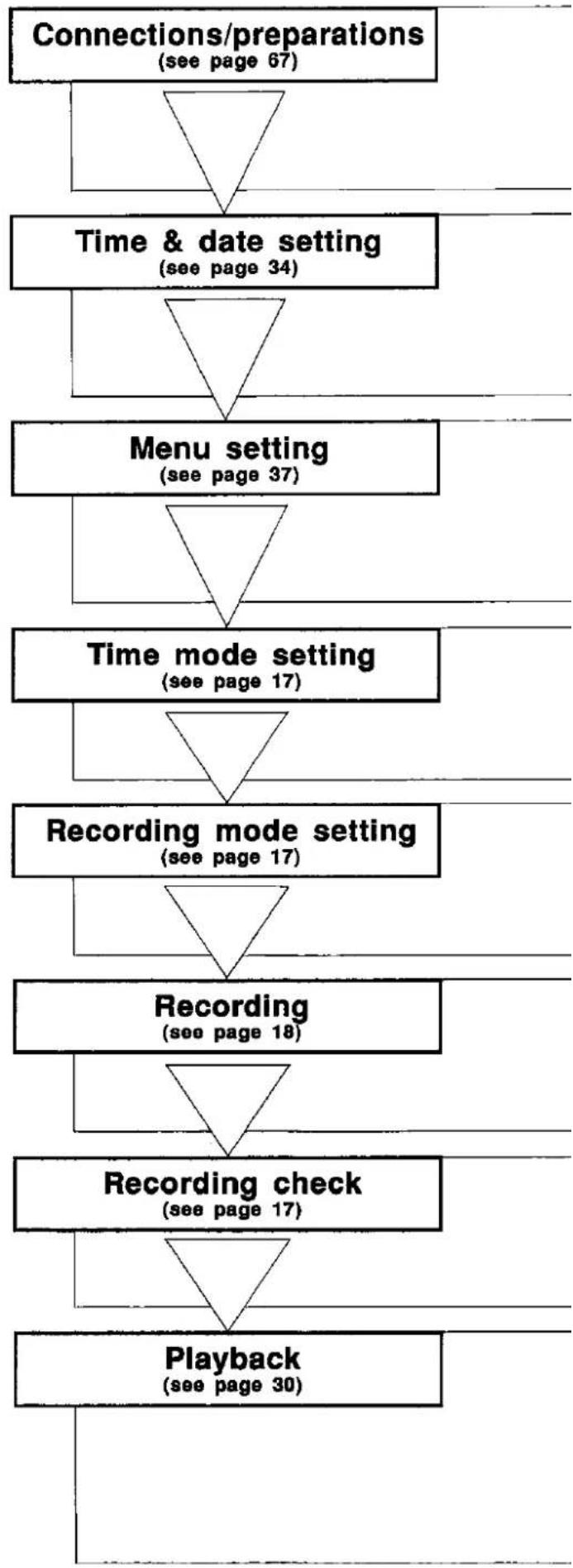
flowchart
graph TD
    A["Connections/preparations\n(see page 67)"] --> B["Time & date setting\n(see page 34)"]
    B --> C["Menu setting\n(see page 37)"]
    C --> D["Time mode setting\n(see page 17)"]
    D --> E["Recording mode setting\n(see page 17)"]
    E --> F["Recording\n(see page 18)"]
    F --> G["Recording check\n(see page 17)"]
    G --> H["Playback\n(see page 30)"]
| Connect the cameras, monitors, sequential switcher, alarm switch,sensor switch, buzzer, etc. to the VTR as required.Turn on the power to the VTR and to the units which have beenconnected to it.Check that a clear picture from the camera appears on the TVmonitor.Insert the cassette tape. | |
| PROGRAMMENUOFFTIMEADJ | |
| PROGRAMMENUOFFTIMEADJ | |
| TIME MODE | |
| REC MODE | |
| ●REC | |
| RECREVIEW | |
| REV PLAY PLAY | |

flowchart
graph TD
    A["<<DISPLAY>>\nMODE T/D\nCHARACTER WRITE\nPOSITION L-UPPER\nTIME SELECT 24HOURS\nDATA ON\nTIME ON\nT-MODE ON"] --> B["<<VTR MODE SELECT 1>\n(REC T-MODE) OFF\n(TAPE IN)\nMODE STOP\n(TAPE END)\nMODE STOP\nALARM IN STOP\n(EJECT OPERATION)\nMODE ELECT"]
    B --> C["<<VTR MODE SELECT 2>\n(POWER LOSS MEMORY)\n$----$$$$$<br>[VIDEO"]\nMODE AUTO\nIN LINE\nS-VHS REC ON\n(TIME ADJUSTING)\nSET TIME 9:00\nOPERATION SLAVE]
    C --> D["<<ALARM/SENSOR REC>\nMODE OFF\nDURATION 0.5MIN\nBUZZER OFF\nREPEAT IN OFF\n[RESET PULSE"]\nINPUT LEVEL HIGH\n["CAMERA SW"]\nTIMING 1FIELD\nMODE TM2]
    D --> E["<<1-SHOT REC>\nFIELD 1\nINTERVAL 3MIN"]
    E --> F["<<INTERNAL TIMER REC>\n[TIMER"] START END T-M\nSUN OFF\nMON OFF\nTUE OFF\nWED OFF\nTHU OFF\nFR1 OFF\nSAT OFF\nDLY OFF]
    F --> G["To return to menu screen 1)"]
    G --> H["<<RS-232C PARAMETER>\nBIT LENGTH 7BIT\nSTOP BIT STOP-1\nPARITY 000\nBAUD RATE 9600"]
    H --> I["<<TIME CODE>\nMODE REGEN\nVITO REC ON\nPOSITION 11H.13H\nTO PRESET 00:00:00:00\nUB PRESET 00:00:00:00"]
    I --> J["To return to menu screen 1)"]

    K["Menu screen 1\nMenu display setting\n• is no indication for AG-6040."] --> L["Menu screen 2\nVTR mode setting 1"]
    L --> M["Menu screen 3\nVTR mode setting 2\n• is no indication for AG-6040."]
    M --> N["Menu screen 4\nAlarm recording mode setting"]
    N --> O["Menu screen 5\n1-shot recording mode setting\n• is no indication for AG-6040."]
    O --> P["Menu screen 6\nInternal timer recording mode setting"]
    P --> Q["Menu screen 7\nRS-232C parameter setting"]
    Q --> R["Menu screen 8\nTime code setting"]
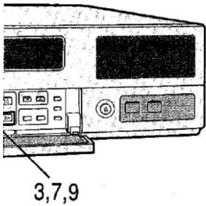
Basic First Steps For Operation

When starting to use the VTR, make sure that you have acquainted yourself with at least these basic operations.
■ Installing the cassette
1

Press the middle part of the cassette.
Do not force it in!

■ Ejecting the cassette
2
Press this button.
(No operation results unless the control is pressed down firmly.)
■ Recording
3

Press this button.
[See Note 1]

■ Playback
4

Press this button.

■ Stop
5

Press this button.
This will stop all tape travel.


■ Fast forwarding/rewinding
6

Press one of these buttons when the tape is stopped.

■ Search forward/search reverse
7

Keep one of these buttons depressed during playback.
[See Note 2]

■ Temporarily suspending recording
8

Press this button during recording.
[See Note 3]

■ Still-picture playback
9

Press this button during playback.
[See Note 3]

■ Frame advance/reverse playback
10

Press one of these buttons during still-picture playback.
[See Note 3]

NOTES
[Note 1]
If the cassette's accidental erasure prevention tab is missing, the cassette is ejected. (See page 36)
[Note 2]
Continuous search forward or search reverse operations can be initiated by pressing the FF or REW button once if the alarm search mode has been established.
(See page 32)
[Note 3]
The pause or still-picture mode gives way to the stop mode when a fixed period of time has elapsed. This is to protect the tape.
[Auto head cleaning function]
Any dirt on the video heads is automatically removed whenever recording or playback is started from the stop mode, whenever the unit is placed in the stop mode from the recording or playback mode so that, as a result, a clear picture is obtained.
Nevertheless, the video heads may become dirty after prolonged use of the VTR, in which case they must be cleaned. The optional (non-abrasive) cassette for head cleaning is recommended.
Basic First Steps For Operation
(Continued)

■ Monitoring the recording
1

Press the button during recording.
[See Note 1]
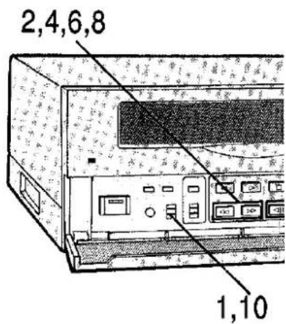
■ Adjusting the tracking
2

Press both but- tons together during playback.
If the tracking still cannot be adjusted, press the "+" or "-" button separately. (See page 31)
■ Adjusting the picture quality
3
Turn this control during playback.
(See page 31)
■ Bringing up the menu screen
4

Set the switch to MENU when the tape has stopped or when it has been ejected.
- is no indication for AG-6040.
![[DISPLAY] MODE +/0 CHARACTER WHITE POSITION L-UPPER TIME SELECT 24HOURS DATA ON TIME ON T-MODE ON](/content/2026/06/1329859/images/6d9d61c4dde4d5e263bb61af9115d00724b10066887e18ad2b3a430559ac5041.jpg)
■ Bringing up the time setting display
5

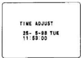
Set the switch to TIME SET when the tape has stopped or when it has been ejected.
- When the switch is set to this position during recording, the time setting screen will be recorded.
TIME ADJUST
25-5-98 TUE 11 53 00


■ Selecting the recording mode
6

Press this button and select the mode before proceeding with the recording.
[See Note 2]

■ Locking the recording
7

Set the switch to "1" or "2" during recording.
[See Note 3]
■ Selecting the time mode
8

Press this button before (or during) recording or playback.
[See Note 4]

■ Switching between the time and tape counter display
9
The display is switched each time this button is pressed.

■ Resetting the tape counter
10
Press this button while the counter value is displayed.

NOTES
[Note 1]
The pictures immediately before the REC REVIEW button was pressed during recording are partially played back, and then operation returns to the recording mode. (It takes about 3 seconds for the playback picture to appear.)
The cassette mark (☐) on the display flashes if it was not possible for the proper video level to be obtained after the recording review operation due to dirt on the heads or deterioration of the tape. (See page 77) • It is also possible to set the function which automatically carries out the recording review each time the recording starts.
(See page 66)
[Note 2]
The recording mode is set to the EXTERNAL TIMER, INTERNAL TIMER and NO DISPLAY in sequence each time the REC MODE button is pressed.
When the internal timer mode is established, the power is set OFF.
(See page 27)
[Note 3]
When recording is locked, the regular operations can no longer be performed.
1: Recording review only.
OFF: Regular operations can be performed.
2: Recording review, eject only.
(The HOUR METER button always can be operated.)
[Note 4]
The time (hour) modes are as follows.
3H mode: Standard mode
L12/L24H mode: Continuous low-speed (linear slow) mode
24\~480H mode: Intermittent (time lapse) mode
000H mode: 1-SHOT mode
Refer to page 42 for more details on the recording time modes.

The sequence of steps to be taken from the start of recording to its completion is described on these pages.
1
■ Connect the equipment and prepare the units for operation. (See page 67)
■ Turn on the power.
■ Install a cassette with its accidental erasure prevention tab intact. (See page 36)
[See Note 1]
2

Adjust the time and date.
(See page 34)
[See Notes 2, 3]
3

Set the menu.
(See page 37)
[See Note 3]

4

Press these buttons to set the hour mode.
[See Note 4]

5
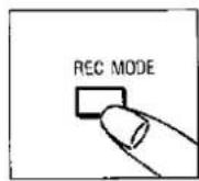
Press this button to set the recording mode.
[See Note 5]
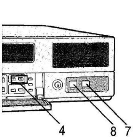

6

Set the switch to "1" or "2" to lock the recording.
7

Press this button to start the recording.

8

The recording can be monitored if this button is pressed while the recording is in progress.
9
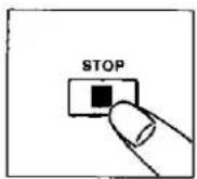
Press this button to stop the recording. [See Note 6]
■ Recommended tapes
This time lapse recorder has been designed to yield the high degree of reliability which is required in such applications as monitoring, security and observation. In order to assure this reliability in recording, it is recommended that the following Panasonic tapes be used.
VHS tapes: NV-E30/E60/E90/E120/E180 series
S-VHS tapes: NV-SE30EM/SE60EM/SE180EM series
NOTES
[Note 1]
The automatic recording function can be set on menu screen 2.
(See page 42)
[Note 2]
The automatic time setting function can be set on menu screen 3. (Model AG-6730 only)
(See pages 45, 64)
[Note 3]
Upon completion of the time and menu setting, be sure to set the PROGRAM switch to "OFF."
[Note 4]
When "REC T-MODE" on menu screen 2 is at any setting other than "OFF," the time (hour) mode will be set to the setting which was set by "REC T-MODE."
(See page 42)
[Note 5]
When the "internal timer recording" mode is selected, the power will be turned off.
(See page 27)
[Note 6]
If the recording lock switch has been set to a position other than OFF, first return it to the OFF position, and then press the stop button.


When there is an alarm input during time lapse recording, the alarm recording function changes the time mode to a setting which enables recording to be conducted clearly so that the scene of the emergency will be recorded faithfully.
1 Complete steps 1 to 4 on page 18.
2

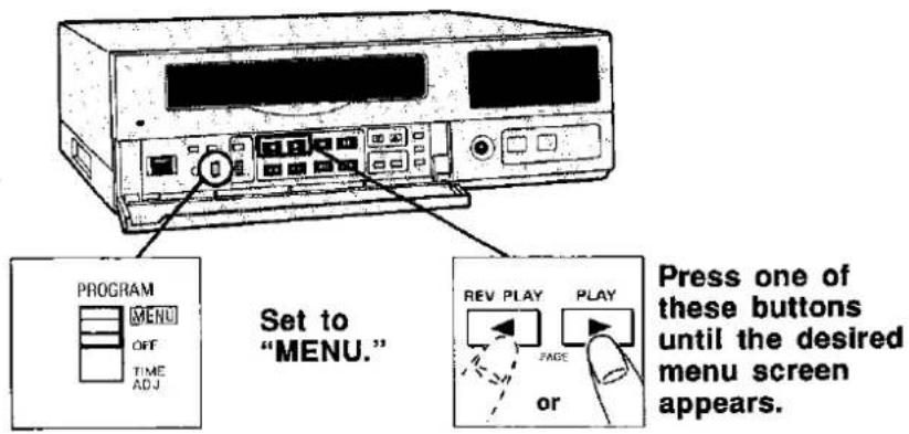
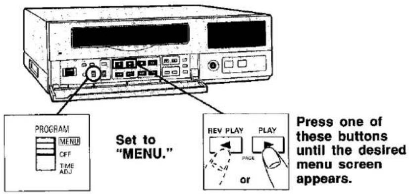
Set this switch to "MENU."
• □ is no indication for AG-6040.

3
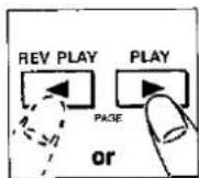
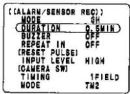
Press one of these buttons to display menu screen 4.
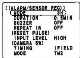
![[ (ALARM/SENSOR REC)] MODE OFF OURATION 0.5MIN BUZZER OFF REPEAT IN OFF (RESET PULSE) INPUT LEVEL HIGH (CAMERA SW) TINING 1FIELD MODE TM2](/content/2026/06/1329859/images/31003b6d5fb6b9fb9f3a9fa806ba0ca7264fe44fcca92e210e5b38359a9ab294.jpg)
4

Press this button.

5
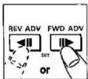
Press one of these buttons to select the recording time mode for alarm recording.
[See Note 1]
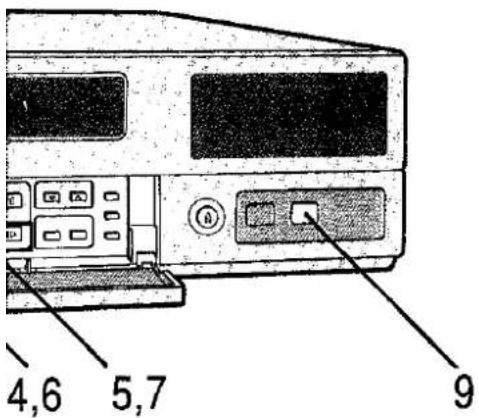
[Menu setting buttons]
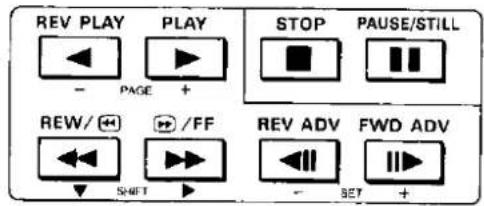
6

Press this button.
7

Press one of these buttons to select the recording duration.
[See Note 2]

8

Set this switch to OFF.
[See Note 3]

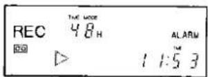
9

Press this button.
10
Recording now commences.
Refer to page 18 for details on the recording procedure.
(Continued overleaf)
NOTES
[Note 1]
- Set to OFF when alarm recording is not going to be performed.
- "ALARM" appears on the display when "MODE" is set to any position other than "OFF."
• The recording time setting options are listed below:
3-, L12-, L24-, 24-hour, NO CHANGE
(See page 46)
[Note 2]
The "recording duration" is the length of time during which alarm recording is executed. (See page 46)
[Note 3]
The settings made on the menu screens are entered when the PROGRAM switch has been set to "OFF."
[Other notes]
Besides the settings mentioned here, the following can also be set on menu screen 4.
- Buzzer ON/OFF during alarm recording (BUZZER)
- Repeat-in function setting (REPEAT IN)
- Alarm reset pulse level selection (RESET PULSE)
- Camera switchover timing (CAMERA SW) (See page 46)


■ The alarm recording mode is established when there is an alarm input.
Alarm input ↓
11
| Recording | Alarm recording | Recording | |
| Recording duration | |||
Faithful recording in the time (hour) mode set
- Once an alarm recording is conducted, "alarm" flashes on the display. Pressing the stop button turns off the display.
12
![PANASONIC AG-6040E - [Other notes] - 3](/content/2026/06/1329859/images/fbbd9796471e19426c6904aff30471683de2f75c2de4b3a8137ac25e5248da41.jpg)
Press this button to stop recording.
Sensor (emergency) recording mode
- Even if the power is off or operation has stopped, sensor (emergency) recording is started as soon as there is an alarm input.
- What happens in the sensor recording and the alarm recording mode is the same.
- The sensor recording function does not work when "MODE" on menu screen 4 is set to "OFF."
Alarm input ↓
| PowerOFF/operationstopped/internaltimer on standby | Sensor recording | PowerOFF/operationstopped/internaltimer on standby |
↑ Recording is started with the settings made on menu screen 4.
Alarm memory recall function
This function stores in the memory the dates and number of times that alarm recording has been activated.
Right side of sub panel

When this is pressed, the alarm list is displayed.
- Data for the last alarm recordings (up to 8) is stored.
- The alarm count extends up to 99, after which the count returns to 00.
- The memory can be cleared by pressing the RESET button while the alarm recall screen is displayed.
- The display is cleared automatically after 30 seconds have elapsed. It is also cleared by pressing the ALARM RECALL button again.
- As with alarm recording, sensor recording data is also stored in the alarm memory.
Monitor
![[ (ALARM RECALL MEMORY) ] NO. DATE TIME 09 22-10-98 7:00 08 09-10-98 6:00 07 01-10-98 7:00 06 28- 9-98 12:00 05 21- 9-98 9:00 04 12- 9-98 10:00 03 13- 8-98 17:00 02 11- 8-98 23:00](/content/2026/06/1329859/images/a9ec3aaebb5e3b4576aba717c06ba8a9c53ab8be9a46ed77001c25a3abcc10c5.jpg)
Alarm number:
The data on the most recent alarm recordings appears in chronological order with the latest at the top.
Dates and times of alarm Inputs
■ The following appears on the screen when there has been no alarm recording or when the alarm memory has been reset.
| [ (ALARM RECALL MEMORY) ] | ||
| NO. | DATE | TIME |
| ** | ***-***-*** | ***:*** |
| ** | ***-***-*** | ***:*** |
| ** | ***-***-*** | ***:*** |

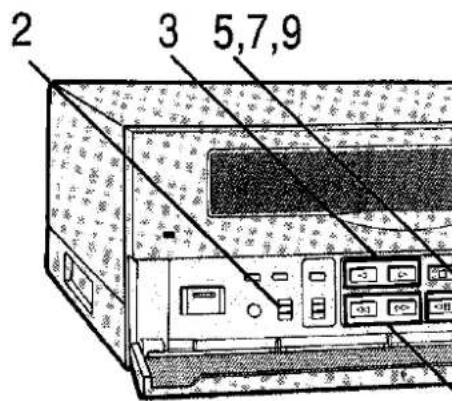
Using the internal timer, recording can be made to start and finish at any time settings.
1 Complete steps 1 and 2 on page 18.
2
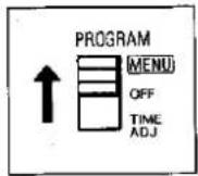
Set this switch to "MENU."
• □ is no indication for AG-6040.
[See Note 1]
![([DISPLAY]) MODE T/O CHARACTER WHITE POSITION L-UPPER TIME SELECT 24HOURS DATA ON TIME ON T-MODE ON](/content/2026/06/1329859/images/cb50c6f1fdbc12baca892bda621d7c2fc9d690b4b51c74871d7e9ececfb7535e.jpg)
3

Press one of these buttons to display menu screen 6.
![([INTERNAL TIMER REC ]) (TIMER) START END T-M SUN OFF MON OFF TUE OFF WED OFF THU OFF FRI OFF SAT OFF DLY OFF](/content/2026/06/1329859/images/1495c669abd75a8a81eae579282cd69c85d03f2090647e38796bed7e5e2c20e8.jpg)
↓ This is the first step for the weekly timer setting.
4
Press this button.
![([INTERNAL TIMER REC]) (TIMER) START END Y-M SUN OFF MON OFF TUE OFF WED OFF THU OFF FRI OFF SAT OFF DLY OFF](/content/2026/06/1329859/images/ad5a422c0dde5395dad50e10872b031e7fd4b5fbf935b484636a3fc810f7f260.jpg)
5

Press one of these buttons to select "ON."
[See Note 2]


natural_image
Line drawing of a computer monitor with control panel and drive buttons (no text or symbols)4,6,8,10
[Menu setting buttons]

6

Press this button.
This sets the start time.

7

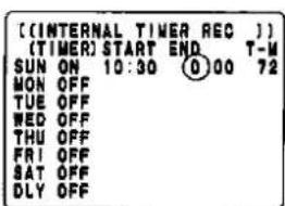
Press one of these buttons to set the "hours" of the start time.
![((INTERNAL TIMER REC)] [TIMER] START END T-W SUN ON ⑩ 00 0 00 72 MON OFF TUE OFF WED OFF THU OFF FRI OFF SAT OFF DLY OFF](/content/2026/06/1329859/images/28f2d7a0219a4fc1f862d5d060072e011139866dff462e6c66b68d40f694dc00.jpg)
8

Press this button.

9

Press one of these buttons to set the "minutes" of the start time.

10

Press this button. This sets the end time.
↓ (Continued overleaf)
NOTES
[Note 1]
The menu screen can be displayed only when the VTR is in the stop or eject mode.
[Note 2]
Keep the PROGRAM switch at the "OFF" position if timer recording is not going to be set.
[Other notes]
Be sure to complete the date/time setting stage before setting the internal timer.
Internal Timer Recording
(Continued)

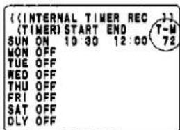
11 Set the "hours" and "minutes" of the end time in the same way as for the start time (steps 7 to 9).
12
Press this button.
13
Press one of these buttons to select the recording hour mode. [See Note 1]

14
Repeat steps 4 to 13 to set the recording start and end times and the recording time mode (in hours) for each day of the week.
↑ This is the last step for the weekly timer setting. [See Note 2]
↓ This is the first step for the daily timer setting. [See Note 2]
15

Press this button.


[Menu setting buttons]

16
Press one of these buttons to select "ON."
[See Note 3]

17
Repeat steps 7 to 13 to set the recording start and end times and the recording time mode (in hours) in the same way as for the weekly timer.
18

Set this switch to the "OFF" position.
[See Note 4]

19

Press this switch to display "INTER-NAL TIMER."
[See Note 5]

20

To release the mode, press this switch and turn off the "INTER-NAL TIMER" display.

NOTES
[Note 1]
The daily timer takes priority in terms of the recording time mode (in hours) when daily timer and weekly timer settings overlap the same time zones. (See page 51)
[Note 2]
Weekly (day of the week) timer
The timer can be set for recording at different times each day of the week.
Daily (every day) timer
The timer can be set for recording at the same time every day.
[Note 3]
When the daily timer is not going to be set, press one of the buttons in step 16 and set "OFF."
[Note 4]
The settings made on the menu screen are entered when the PROGRAM switch is returned to the "OFF" position. Once set and entered, the settings are retained semi-permanently.
[Note 5]
When the recording mode is set to "INTER-NAL TIMER," the power is switched off. At the set time, recording will start automatically.
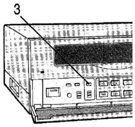
By connecting an externa timer to the VTR, the power to the VTR can be switched ON and OFF to perform timer recordings.
1 Complete step 1 to 4 on page 18.
2 Connect the external timer.
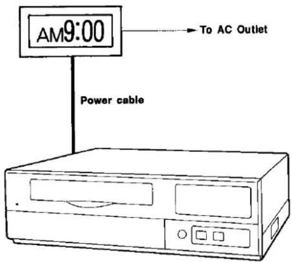
■ Leave the VTR's power on until the setting procedure is completed.
![PANASONIC AG-6040E - [Note 5] - 4](/content/2026/06/1329859/images/cffe55c592c8b726431248d0140eee2d1622a20b401ce83faae2a8e28f77d25c.jpg)
natural_image
Line drawing of a computer monitor with control panel and buttons (no text or symbols)3
![PANASONIC AG-6040E - [Note 5] - 5](/content/2026/06/1329859/images/1d8a04716ede341858ca93d787dee7e1d7ab1eb1e4bffd91eead36eb91f2d9bf.jpg)
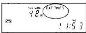
Press this button to display "EXTERNAL TIMER."
[See Note 1]
![PANASONIC AG-6040E - [Note 5] - 6](/content/2026/06/1329859/images/eb9cd588c0d2ff8b3a6761a518e4dfe0591ad21153695a44f66dc11cb33f5898.jpg)
4
Set the external timer.
[See Note 2]
5
Recording starts at the time set by the external timer.
6
![PANASONIC AG-6040E - [Note 5] - 7](/content/2026/06/1329859/images/cfc8159183de8afabbb0811e50961b114a371477aacda07d4c27e368da370f79.jpg)
To release the mode, press this button with power supplied to the VTR and clear the "EXTERNAL TIMER" display.
![PANASONIC AG-6040E - [Note 5] - 8](/content/2026/06/1329859/images/355dae950658bff877910b2331e526863ff1fd714e9c39110a65ba43737e5b92.jpg)
NOTES
[Note 1]
When a cassette has not been installed or when the accidental erasure prevention tab on the cassette installed has been broken out, the buzzer sounds and "EXTERNAL TIMER" flashes.
[Note 2]
For details on how to set the external timer, refer to the operating instructions accompanying the timer.
[Other notes]
In the external timer recording mode, sensor recording will not start even with an alarm input if the VTR's main power is OFF.

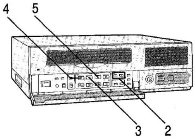
This operation visually displays what has been recorded.
1
■ Complete the connections and ready the units connected for operation. (See page 67)
■ Turn on the power.
■ Install a prerecorded cassette.
■ Complete the connections and ready the units connected for operation. (See page 67)
■ Turn on the power.
■ Install a prerecorded cassette.
2

Press one of these buttons to select the time (hour) mode.
[See the section on the time modes on the right-hand page.]

3

Press this button for regular playback.

4

Press this button for reverse playback.
Reverse playback of 1-shot recording is not possible.
5
Press this button to stop playback.
| Tracking adjustment | ||
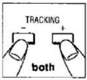
| Adjust the tracking if noise similar to that shown below appears on the playback picture. | This VTR comes with an auto tracking function to obviate the need to adjust the tracking under normal circumstances. However, should noise similar to that shown on the left ap-pear, re-adjust the tracking.Press the "+" and "-" buttons at the same time.If noise still appears, press the "+" and "-" buttons separately. | |
 |  | |
| Vertical Lock Adjustment (model AG-6040 only) | ||
 | If picture jitters vertically in the Still mode, adjust the V-Lock Control on the bottom panel of VTR using the screwdriver. If the TV Monitor has a vertical hold control, adjust the control together with the V-Lock Control. | |
| Picture quality adjustment | |
When adjusting the playback picture:  | ■ Turning the control clockwise yields a sharply defined picture. ■ Turning the control counterclockwise yields a softly defined picture. |
| Time modes |
| ■ Bear in mind the following points when playing back an intermittently recorded tape in the same time mode.· The picture may shake slightly in the lateral direction but this is not indicative of malfunctioning.· There may be some slight distortion at the top of the picture but this is not indicative of malfunctioning.· The picture may dance in both L12 and L24 modes. This is normal and not indicative of malfunctioning.· The sound is not reproduced perfectly. This is normal and not indicative of malfunctioning. |
| ■ Still pictureA clear picture image can be obtained by playing back a recorded tape in the same time mode. |
| ■ When a tape recorded in a 12H or longer mode is played back in the 3H mode, it can be played back at quick motion. |
| ■ If, when the sound was recorded, the mode in which the sound was recorded differs from the mode in which it is played back, the pitch of the sound will also change. |
| Other notes |
| ■ No sound will be heard during reverse playback.■ Reverse playback is not possible with the tape recorded in the 1-shot recording mode.■ The picture may dance while the tape is being played back in any L (linear slow) mode. This is normal and not indicative of a failure. |


These operations are for initiating search playback and alarm search playback.
■ Search playback (search forward/search reverse)
1
Press this button to start playback.
2

Keep one of these buttons depressed.
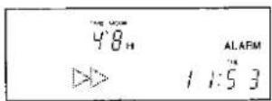
[See Note 1]
3

Release the button to return to regular playback.

■ To continue the search operation, establish the alarm search mode. (See right-hand page)
- If the fast forward or rewind button is pressed during playback, the search operation is performed continuously.
- When the play button is pressed again, operation returns to regular playback.
■ Alarm search procedure
1

Press this button and set the VTR to the stop mode.
2

Press this button to display "AS." [See Note 2]

3

Press one of these buttons to fast forward or rewind the tape.

4
■ The first alarm recorded section on the tape is searched in the direction corresponding to the button pressed, and the VTR is set to the still-picture playback mode. [See Note 3]
5
Press this button to play back the section.

NOTES
[Note 1]
If the REW button is pressed during search playback, the tape will be played back in the reverse direction at 7 times the regular tape speed; if the FF button is pressed instead, it will be played back in the forward direction at 7 times the regular tape speed.
[Note 2]
To release the alarm search mode, press the ALARM SEARCH button again and clear "AS" from the display.
[Note 3]
Only an alarm recorded section which was recorded in the 3H mode can be searched using the alarm search function.

This section describes how the time and date are set.
1
![PANASONIC AG-6040E - [Note 3] - 3](/content/2026/06/1329859/images/2a63617a55c901564d01eaacb7898e09ec148350cca3613d7cecd962664acda8.jpg)
Set this switch to "TIME ADJ."
[See Notes 1, 2 and 3]
![PANASONIC AG-6040E - [Note 3] - 4](/content/2026/06/1329859/images/e9db5efaf162564cf55cce6ff78bfd387b9e46acf12d9a58fddae0b0e10ca6ec.jpg)
2
![PANASONIC AG-6040E - [Note 3] - 5](/content/2026/06/1329859/images/6a422f9d0b87dc0078c1417ea0a101e84f65ef541fd02e6a35bc51759d23fff2.jpg)
Press this button. "Year" flashes.
![PANASONIC AG-6040E - [Note 3] - 6](/content/2026/06/1329859/images/10de204872a56e34778e672af086eff4896dbd35561c5b7371e2fcc5b4b91b0f.jpg)
3
![PANASONIC AG-6040E - [Note 3] - 7](/content/2026/06/1329859/images/3e87ccd956ace530638592875e56007f7e4b3a46b202aa4f517118e54ab0ac60.jpg)
Press one of these buttons to set the number for the year.
![PANASONIC AG-6040E - [Note 3] - 8](/content/2026/06/1329859/images/4e044e2edf173a18c9f04e2a03852041ce84749b800fb6783455f9a82e18d9b2.jpg)
4
![PANASONIC AG-6040E - [Note 3] - 9](/content/2026/06/1329859/images/c026afbe4c2266128e4a40df51045ddebd31b0c7b7e8e93bade1d18210a67ccd.jpg)
Press this button.
![PANASONIC AG-6040E - [Note 3] - 10](/content/2026/06/1329859/images/10a9c0185f568c617fab498764d753ed0eea01ca515111f922bb725d5076be9c.jpg)
5
Repeat steps 3 and 4 to set the month and then the day.
[Time setting buttons]

6
![PANASONIC AG-6040E - [Note 3] - 13](/content/2026/06/1329859/images/419199c9dff6937292d8baee4ed6dc81a9d77aa340da301f5883c7c861591ae8.jpg)
Press this button after the date (year/month/day) has been set.
[See Note 4]
![PANASONIC AG-6040E - [Note 3] - 14](/content/2026/06/1329859/images/e0e657b36a0bb590724ca1bb93f3bbe7baee192a04b7b4a3bb91a006c2d91c59.jpg)
7
![PANASONIC AG-6040E - [Note 3] - 15](/content/2026/06/1329859/images/26dafa5bf6c5df7522142bca87347fb1392eb92a9043228006107219c451a223.jpg)
Press one of these buttons to set the "hours."
![PANASONIC AG-6040E - [Note 3] - 16](/content/2026/06/1329859/images/67679d9d8b95fc925eb1d5fe4aab7353061decbc30b163dba35df3d91302b56c.jpg)
8
![PANASONIC AG-6040E - [Note 3] - 17](/content/2026/06/1329859/images/ff6a6b9e9e74b841267ef2dcc1a84704b2ee90f88cbe505e7d9ed1d34e8acf8d.jpg)
Press this button once.
![PANASONIC AG-6040E - [Note 3] - 18](/content/2026/06/1329859/images/46a3666e5c22ad69e1074959e12f0bbc0456c8062002d93044b491fd1f28cef6.jpg)
9
![PANASONIC AG-6040E - [Note 3] - 19](/content/2026/06/1329859/images/1c24e79342f572d8c34b2ba47c36435bf6160bfc1f3d5f22f70cfc7944c63259.jpg)
Press one of these buttons to set the "minutes."
![PANASONIC AG-6040E - [Note 3] - 20](/content/2026/06/1329859/images/682460be890e270114210dd50b2cf388bad8aa83e64209c1a0d72cdb1e4c96ff.jpg)
10
![PANASONIC AG-6040E - [Note 3] - 21](/content/2026/06/1329859/images/bcaaf2e8f2c673fb2e3e2efaad5ca3b7398add2075eccd15ee45f030cc2d50a6.jpg)
Set this switch to "OFF."
[See Note 5]
![PANASONIC AG-6040E - [Note 3] - 22](/content/2026/06/1329859/images/1b6e11de20de74ca3f1001a2e6b9bd510df9ada33a4ca6868a25c00a66cf9bbb.jpg)
NOTES
[Note 1]
If the time is set during recording, the screen on which the time was set will be recorded.
[Note 2]
The screen appears below on the TV monitor.
TIME ADJUST
01-1-96 THU 0 00 00
[Note 3]
The default display is 01 1 98 (January 1, 1998). The date can be displayed up to 31 12 13 (December 31, 2013).
[Note 4]
The default display is 00:00:00. The maximum time which can be displayed is 23:59:59 (although only the hours and minutes actually appear on the display).
[Note 5]
The time starts elapsing from the moment that step 10 is performed. The time can be set accurately if the switch is set to "OFF" as soon as the time signal is heard.
[Other notes]
• The maximum monthly time error is 60 seconds.
- The time and date data will be retained in the event of a power failure provided that it does not last longer than one month (AG-6730) or one week (AG-6040). (For the data to be retained, power must have been supplied for at least 40 hours.)
- Adjustment for leap years is automatic.
![PANASONIC AG-6040E - [Other notes] - 1](/content/2026/06/1329859/images/4ee127842c8dae40201bc5ced943d2a537ff81fb445050cabbff0a2b3792b8fe.jpg)

Operating precautions
If the PAUSE/ STILL button is pressed during recording in any time mode from 3H to L24H, the tape will run in the reverse direction for about 3 seconds before stopping.
When the same button is pressed again, the tape will run for about 3 seconds before recording is resumed.
■ Time lapse recording is performed in the 24H or longer recording time mode. By omitting frames while recording the pictures, it is possible to record over long periods of time. However, since the picture is not continuous, the sound cannot be recorded.
■ When the recording time mode has been set to any position other than "OFF" on menu screen 2, it cannot be changed using the TIME MODE button on the sub panel during recording. When it has been set to "OFF," the time mode can be changed even during recording using the TIME MODE button on the sub panel.
■ When the power is restored after a power failure and power is again supplied to the VTR, the power loss memory screen shown below will appear on the monitor screen for 15 seconds.
While the power loss memory display appears on the monitor screen, menu screen and time settings cannot be conducted.
POWER LOSS
05 31-10-98
17:42
■ The TIME MODE button does not work during alarm recording.
■ When the REC button is pressed during still-picture playback, the VTR is set to the recording pause mode, and the E-E picture appears on the monitor.
If frame advance and frame reverse operations are repeated many times in the same place on the tape, noise may appear. It will disappear when frame advance or frame reverse is continued.
Accidental erasure prevention tab
■ Valuable recordings can be protected from accidental erasure by breaking out the tab on the cassette.
■ To re-record over a tape in a cassette whose tab has been broken out, stick an adhesive tape over the tab opening.

natural_image
Diagram of a mechanical device with an inset showing a tool interacting with a component (no text or symbols present)
natural_image
Diagram of a car with an arrow indicating upward motion, enclosed in a circle (no text or symbols)Break out the tab in the direction of the arrow.
Menu Screens
Outline of Menu Screens 38
Menu Screen 1 (Screen Display Settings) 40
Menu Screen 2 (VTR Mode Settings 1) 42
Menu Screen 3 (VTR Mode Settings 2) 44
Menu Screen 4 (Alarm Recording Mode Settings) ..... 46
Menu Screen 5 (1-Shot Recording Mode Settings) ..... 48
Menu Screen 6 (Internal Time Recording Mode Settings) ... 50
■ Menu Screens Appearing Only When Optional RS-232C Interface Adaptor AG-IA670 Is Mounted
Menu Screen 7 (RS-232C Parameter Settings) ..... 52
Menu Screen 8 (Time Code Settings) 54
Checkpoints For Menu Setting 56


Set the switch to "MENU."
• The previous setting screen appears.
- Menu screen 1 appears when settings are to be performed for the first time.
The VTR's many functions can be set on-screen.
■ Menu screen 1 (screen display settings)
![[OISPLAY] MODE T/D CHARACTER BLACK POSITION L-UPPER TIME SELECT 24HOURS DATA ON TIME ON T-MODE ON](/content/2026/06/1329859/images/615b956f6301639d13f5cbe864a586f50617270888b986eebf6dba9db4c46e1e.jpg)
The information displayed on the TV monitor is set on this screen.
• □ is no indication for AG-6040.
■ Menu screen 2 (VTR mode settings 1)
![[VTR MODE SELECT 1] (REC T-MODE) OFF (TAPE IN) MODE STOP (TAPE END) MODE STOP ALARM IN STOP (EJECT OPERATION) MODE EJECT](/content/2026/06/1329859/images/2b180acfa36bcfac5e5efa25e2c10e8c4e9f09c9b6bfec32a2c8c287c91c77fe.jpg)
• Recording time mode setting
- Setting for operation when cassette is installed
• Tape-end operation settings
- Eject operation setting
■ Menu screen 3 (VTR mode settings 2)
![[VTR MODE SELECT 2] [POWER LOSS MEMORY] $$---$$ [VIDEO] MODE AUTO IN LINE S-VHS REC ON [TIME ADJUSTING] SET TIME 9:00 OPERATION SLAVE](/content/2026/06/1329859/images/2c9193c6692f3522bd6b435d37d28bc24f773f8737d33c08a78c92366631a1cb.jpg)
• Power loss memory display
• Video signal selection (model AG-6730 only)
• Time adjustment function settings (model AG-6730 only)
■ Menu screen 4 (alarm recording mode settings)

• Alarm recording mode settings
- Reset pulse selection
- Camera switch setting
■ Menu screen 5 (1-shot recording mode settings) (model AG-6730 only)
![[(1-SHOT REG)] FIELD 1 INTERVAL 3MIN](/content/2026/06/1329859/images/8308a705f7d68449dfa0bb920da7b06021c0d1a302187e93ee6f44b21a9d1456.jpg)
• 1-shot recording mode setting

natural_image
Line drawing of a computer monitor with control panel and buttons (no text or symbols)[Menu setting buttons]

■ Menu screen 6 (internal timer recording mode settings)
![[[INTERNAL TIMER REG ]] [T | MER] START END T-W SUN OFF MON OFF TUE OFF WED OFF THU OFF FRI OFF SAT OFF DLY OFF](/content/2026/06/1329859/images/433502e2ecb3d22ba08203f04f43257171f1019de5985bbbfc59d2ecb672e435.jpg)
• Daily timer settings
• Weekly timer settings
■ The menu screens below appear only when the optional RS-232C Interface Adaptor AG-IA670 is installed.
(See page 83)
■ Menu screen 7 (RS-232C parameter settings)
![[(RS-232C PARAMETER)] BIT LENGTH 781T STOP BIT STOP-1 PARITY ODD BAUD RATE 9600](/content/2026/06/1329859/images/aaffaad7d987ba2df590695dd05b0066f8fa47b8db52fd44362bd0f9a3d38264.jpg)
• RS-232C parameter settings
■ Menu screen 8 (time code settings)
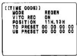
• Time code settings
NOTES
- The menu screens can be displayed only when the VTR is in the stop or eject status.
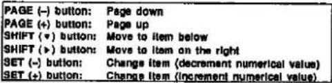
- Menu screen setting method
1) Set the PROGRAM switch to "MENU."
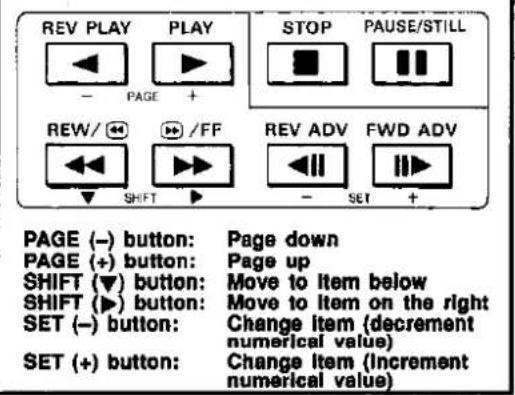
2) Use the "+" and "-" buttons to select the desired menu screen. The page following the last page is the first page; the page before the first page is the last page.
3) The first line flashes when the (▼) SHIFT button is pressed.
4) Select the setting items using the (▼) and (▶) SHIFT buttons.
5) Use the "+" and "-" SET buttons for the settings.
6) Upon completion of the settings, return the PROGRAM switch to the "OFF" position. The item settings will now be entered.
[Displaying the screens]
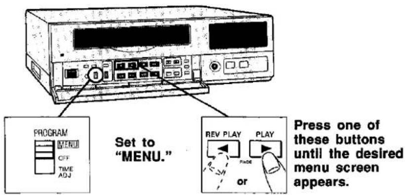
[Menu setting buttons]
■ Time display ON/OFF

Set the time display ON or OFF.
■ Time mode display ON/OFF

Set the time mode display ON or OFF.
■ Regular screen

NOTES
[Note 1]
Time and date display screen

Lap time display screen
(model AG-6730 only)
The total recording time starting from the point in time when recording commenced is indicated in a second increments regardless of the present time. (The recording time is not incremented in the recording pause mode.)
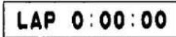
When the RESET button is pressed, the lap time display can be reset to "0:00:00".
Page count display screen
(model AG-6730 only)
During 1-shot recording, each frame recorded counts as a page, and the total number of pages (frames) is displayed on this screen. (For details on 1-shot recording, see pages 48, 60.)

When the RESET button is pressed, the page count display can be reset to "0."
[Other notes]
The Item settings are entered when the PROGRAM switch is returned to the "OFF" position.

![[ (VTR MODE SELECT 1) ] [REC T-MODE] OFF [TAPE IN] MODE STOP [TAPE END] MODE STOP ALARM IN STOP [EJECT OPERATION] MODE ELECT](/content/2026/06/1329859/images/c38543325fc22b947db628e76cd466ca649a89baefd2c8e334c99b7dfe605374.jpg)
The VTR mode settings are performed on this screen.
■ Recording time mode selection
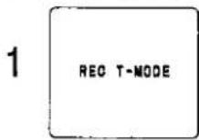
The recording time mode is set. When the recording is started, the unit is always placed in the time mode which was set. (See page 56)
OFF: The time mode can be set as desired using the time mode button on the VTR's sub panel. The mode can be changed even during recording.
3H: 3-hour mode (compatible with the standard mode of ordinary VTRs).
L12H: 12-hour mode (linear slow recording)
L24H: 24-hour mode (linear slow recording)
24H: 24-hour mode (time lapse recording at 0.18 sec. intervals)
48H: 48-hour mode (time lapse recording at 0.34 sec. intervals)
72H: 72-hour mode (time lapse recording at 0.5 sec. intervals)
84H: 84-hour mode (time lapse recording at 0.58 sec. intervals)
120H: 120-hour mode (time lapse recording at 0.82 sec. intervals)
180H: 180-hour mode (time lapse recording at 1.22 sec. Intervals)
240H: 240-hour mode (time lapse recording at 1.62 sec. Intervals)
480H: 480-hour mode (time lapse recording at 3.22 sec. intervals)
000H: 1-shot recording mode (see pages 48, 60).
[See Notes 1 and 2]
■ Sound cannot be recorded in the time lapse recording or 1-shot recording modes.
■ Selection of operation when cassette is installed

Select how the VTR is to operate when the cassette is installed.
STOP: Stop mode
REC: Automatic recording mode [see Note 3]
AUTO: When a cassette tape is loaded, it is first rewound to its beginning and then recording is commenced automatically.
■ Selection of operation at tape-end
3
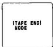
Select how the VTR is to operate at the tape-end. STOP: Stop mode
BUZZER: Stop and the buzzer sounds.
REW: Automatic rewinding mode [see Note 4]
REPEAT: Repeat recording mode [see Note 5]
[Displaying the screens]

[Menu setting buttons]

■ Setting auto rewind function release when an alarm Input is generated
4

This setting selects whether the auto rewind function is to be released when there is an alarm input while recording is in progress.
STOP: The auto rewind function is released. The VTR is set to the stop mode at the tape-end.
CONTINUE: The auto rewind function is not released.
■ Selection of cassette EJECT button
5

Select the operation which is to be performed when the EJECT button is pressed.
EJECT: The cassette is ejected as soon as the button is pressed.
AUTO: When the button is pressed, the tape is automatically rewound to its start before the cassette is ejected.
NOTES
[Note 1]
The VTR's time (hour) modes are based on the use of a 3-hour tape. If the cassette used has a different duration, the hour modes will be as follows:
• 120-minute tape: 2/3 of selected time
• 90-minute tape: 1/2 of selected time
- 60-minute tape: 1/3 of selected time
• 30-minute tape: 1/6 of selected time
[Note 2]
Linear slow recording
With this kind of recording, the tape travel speed is reduced and the sound is recorded continuously. (Sound can be recorded.)
Time lapse recording
Long-duration recording is possible by recording while advancing the tape intermittently. (Sound cannot be recorded.)
[Note 3]
Automatic recording mode
Recording is started automatically just by installing the cassette.
[Note 4]
Auto rewind function
When the tape reaches its end during recording, it is automatically rewound to its start.
[Note 5]
Auto repeat recording function
When the tape reaches its end during recording, it is automatically rewound to its start and recorded again (or repeatedly).
[Other notes]
The item settings are entered when the PROGRAM switch is returned to the "OFF" position.

![[ (VTR MODE SELECT 2) ] [POWER LOSS MEMORY] **-*--*: *$ [VIDEO] MODE AUTO IN LINE S-VHS REC ON (TIME ADJUSTING) SET TIME 9:00 OPERATION SLAVE AG-6730 only](/content/2026/06/1329859/images/c77ab0bb81522c156368eeadc362c51272ecb2d21b3a75f099d6fd4ed3cf6fda.jpg)
The VTR mode settings are performed on this screen.
■ Power loss memory display
[See Note 1]
1
(POWER LOSS MEMORY)
This screen displays the power loss memory.
- When the SHIFT (▼) button is pressed so that the number flashes and then the SET "+" or "-" button is pressed, data in the memory on up to the last four power failures is indicated in sequence.
- The power loss memory data can be cleared as below.
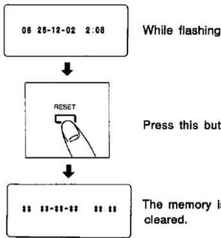
flowchart
graph TD
    A["06 25-12-02 2:08"] --> B["Press this button"]
    B --> C["The memory is cleared."]
    C --> D["RESET"]
- The following display appears for the power loss memory data if the time/date has not been set or when there is no data in the memory.

■ Selecting the video signal mode
2

Select the operation of the auto colour/b&w selector circuit.
AUTO:
The circuit is automatically switched to colour or black-and-white, whichever corresponds to the input signal. (Regular setting) [See Note 1]
COLOUR: For colour signal input only
B/W: For black-and-white signal input only [See Note 2]
[Displaying the screens]

[Menu setting buttons]

■ Selecting the input video signal (model AG-6730 only)
3
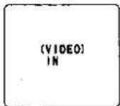
Select the input video signal.
LINE: The signal supplied to the video input connector (line) serves as the input video signal.
S-VIDEO: The signal supplied to the S video connector serves as the input signal.
■ Setting the S-VHS recording mode (model AG-6730 only)
4

Select the S-VHS recording mode.
ON: Whether the tape is VHS or S-VHS is automatically identified, and recording proceeds in the corresponding mode.
OFF: Recording always proceeds in the VHS mode regardless of the type of cassette used. During playback, the tape type is automatically identified.
■ Time adjust function time setting (model AG-6730 only)
5

Set the time.
Only the "hours" can be set.
The "minutes" remains at "00."
Set the time using the set "+" or "-" button.
■ Time adjust function selection (model AG-6730 only)
[See Note 4]
6

Select the time adjust function.
SLAVE: The VTR's time is set by the external switch or master VTR.
MASTER: Using the VTR as the master clock, the time of another VTR is set.
NOTES
[Note 1]
Power loss memory
When power failures have occurred, the number of occurrences together with their dates and times are counted up to a maximum of 99 times, and the data of the 4 most recent occurrences is stored in the memory.
[Note 2]
Do not mix black-and-white and colour signals when supplying them to the video input connectors. This will cause sync fluctuations and generate noise.
[Note 3]
When supplying signals which may cause the circuit to make an error in its automatic identification, set to COLOUR for colour signals and to B/W for black-and-white signals. When colour signals are supplied with a B/W setting or black-and-white signals are supplied with a COLOUR setting, unnatural video signals will be recorded.
[Note 4]
SLAVE mode
- When the rear panel's time adjust input terminal is shorted to ground, the VTR's time is set to the time established in step 5, and pulses (L) are output from the time adjust output terminal.
MASTER mode
- Pulses (L) are output from the time adjust output terminal when the VTR's time tallies with the set time.
[Other notes]
The item settings are entered when the PROGRAM switch is returned to the "OFF" position.

![[ (ALARM/SENSOR REC)] MODE OFF DURATION 0.5MIN BUZZER OFF REPEAT IN OFF [RESET PULSE] INPUT LEVEL HIGH [CAMERA SW] TIMING 1FIELD MODE TM2](/content/2026/06/1329859/images/dd813678b88e6388676d7dddd7ed9e972504b17a507fb2927efd77b4df01ad09.jpg)
The alarm recording mode settings are performed on this screen.
■ Selecting the alarm recording time mode
1

Select the recording time mode when an alarm input is received.
OFF: No alarm recording.
3H: 3-hour mode
L12H: 12-hour mode (linear slow)
L24H: 24-hour mode (linear slow)
24H: 24-hour mode (time lapse)
NO CHANGE: The recording time remains unchanged even if there is an alarm input.
← Tape start Alarm input ↓ Tape end →
| Recording | Alarm recording mode | Recording |
- When there is an alarm input during recording in one of the time lapse modes, the recording time mode switches to the designated mode and the emergency scene is faithfully recorded.
■ Setting the alarm recording duration
2

Set how long the alarm recording is to last from the start to the end.
0.5MIN-3.0MIN: The time can be set in 30-second increments from 0.5 to 3 minutes.
CONTINUE: Alarm recording continues until the tape-end.
MANUAL: Alarm recording is performed while the alarm input continues to be received.
[Displaying the screens]

[Menu setting buttons]

■ Buzzer ON/OFF
3

Set whether the buzzer is to sound during alarm recording.
OFF: The buzzer does not sound.
ON: The buzzer sounds while alarm recording is in progress.
- Press any function button to release the buzzer.
■ Setting the repeat-in function
4

Set whether alarm recording is to proceed when there has been an alarm input while the tape was being rewound automatically in the recording mode.
OFF: No alarm recording.
ACCEPT: Alarm recording [See Note 1]
■ Selecting the alarm reset pulse acceptance level
5

Select the acceptance level of the alarm reset pulse.
HIGH: The high level is set.
LOW: The low level is set. (See page 74)
■ Setting the timing
6
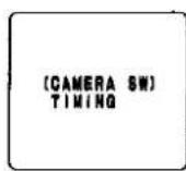
Set the camera switchover timing signal which is to be output by the external sequential switcher during recording.
The cameras are switched every 1-, 2-, 3-, 4-, 5-, 10-, 20-, 25- or 50-fields. [See Note 2]
■ Selecting the camera switchover mode
7
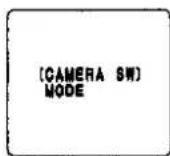
Select whether the camera switching is to be done in field or frame units. [See Note 3]
TM2: Switching in field units.
TM1: Switching in frame units.
NOTES
[Note 1]
When "ACCEPT" is selected in the repeat-in function, be sure to set to other modes than "OFF" in step 1.
[Note 2]
When "TM1" has been selected as the camera switchover mode in step 7, the cameras are switched in frame units.
[Note 3]
Select "TM1" when the frame switcher is connected and "TM2" when any other sequential switcher is connected.
[Other notes]
- The item settings are entered when the PROGRAM switch is returned to the "OFF" position.
- When "MANUAL" is selected for the alarm recording duration, make sure to set the [TAPE END] MODE to "STOP" or "BUZZER".
Menu Screen 5
(1-shot recording mode setting)
(Model-AG-6730 only)
[1-SHOT REC]
FIELD
INTERVAL
1
3MIN
The alarm recording mode settings are performed on this screen.
■ Selecting the 1-shot recording time
1

Select the time for recording one frame in the 1-shot recording mode in field units: 1, 2, 3, 4, 5, 10, 15, 20, 25, 30, 40, 50. [See Note 1]
Setting the interval time for 1-shot recording
2
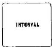
Set the duration of the intervals for 1-shot recording.
1: 1-shot recording at 1-minute intervals.
2: 1-shot recording at 2-minute intervals.
3: 1-shot recording at 3-minute intervals.
Recording time
↓
| Interval duration | Interval duration |
For model AG-6040
The 1-shot recording mode for the model AG-6040 is fixed to the settings given below.
• Time for recording one frame: 1 field
• Interval duration: 3 minutes
[Displaying the screens]

[Menu setting buttons]

■ The lengths of time during which recording can be performed in the 1-shot recording mode are as follows (using a 180-minute tape).
| Interval duration (minutes) | ||||
| 1 | 2 | 3 | ||
| Time for recording one frame (in fields) | 1 | 9,000 | 18,000 | 27,000 |
| 2 | 4,575 | 9,075 | 13,575 | |
| 3 | 3,100 | 6,100 | 9,100 | |
| 4 | 2,362 | 4,612 | 6,862 | |
| 5 | 1,920 | 3,720 | 5,520 | |
| 10 | 1,035 | 1,935 | 2,835 | |
| 20 | 592 | 1,042 | 1,492 | |
| 25 | 504 | 864 | 1,224 | |
| 50 | 327 | 507 | 687 | |
Unit (hours)
NOTES
[Note 1]
The recording interval per field among the fields set is one second.
[Other notes]
The item settings are entered when the PROGRAM switch is returned to the "OFF" position.
Menu Screen 6
(Internal timer recording mode settings)
[ (INTERNAL TIMER REC ) ] (TIMER) START END T-M
SUN OFF MON OFF TUE OFF WED OFF THU OFF FRI OFF SAT OFF DLY OFF
The internal timer recording modes are set on this screen.
■ Internal timer mode ON/OFF
1

Set the internal timer mode ON or OFF.
ON: The internal timer recording mode is established.
OFF: The internal timer recording mode is not established.
■ Setting the timer recording start time
2

Set the time at which the internal timer recording is to start.
Select the setting items using the SHIFT buttons and set the numerical values using the SET buttons.
■ Setting the timer recording end time
3

Set the time at which the internal timer recording is to end.
Select the setting items using the shift buttons and set the numerical values using the SET buttons.
■ Setting the recording time mode
4
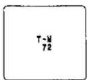
Set the recording time mode for internal timer recording.
3H, L12H, L24H, 24H, 48H, 72H, 84H, 120H, 180H, 240H, 480H, 000H
[Displaying the screens]
[Menu setting buttons]
■ Weekly timer recording
The internal timer recording start and end times can be set once a day for each day of the week from Sunday through Saturday.
For each day of the week, set the internal timer ON/OFF mode, recording start and end times, and recording mode.
■ Daily timer recording
Internal timer recording can be started and ended at the same preset times every day.

■ Using the weekly and daily timers in combination

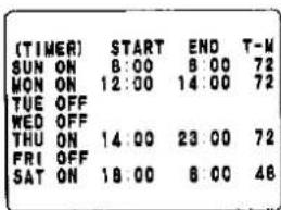
When the settings are as per the screen shown on the left, the weekly and daily timer recording and the actual recording durations on the tape will be as follows.
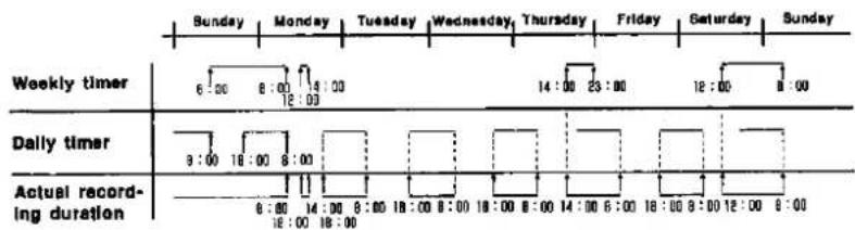
If the recording times overlap in places between the weekly and daily settings, the daily timer recording time (hour) mode takes precedence.
NOTES
[Notes]
- Internal timer recording is not activated if the date and time have not been set.
- The time setting display (24-hour or PM/AM basis) accords with the mode assigned by the time/date setting.
- If the internal timer mode is set "OFF" after the start and end times have been set with the mode "ON", the time setting display will be cleared but will then re-appear when the mode is set back to "ON."
- When the weekly timer and daily timer recording functions are used in combination, the time mode set for the daily timer recording takes precedence if there should be any overlap between the two time settings.
- The item settings are entered when the PROGRAM switch is returned to the "OFF" position.
[Displaying the screens]

[Menu setting buttons]
RS-232C
"RS-232C" is an interface standard for data terminals and data communications equipment employing serial binary data exchange as stipulated under the RS-232 CCIR standard. Using this RS-232C interface, this VTR can be controlled by a personal computer.
Code format
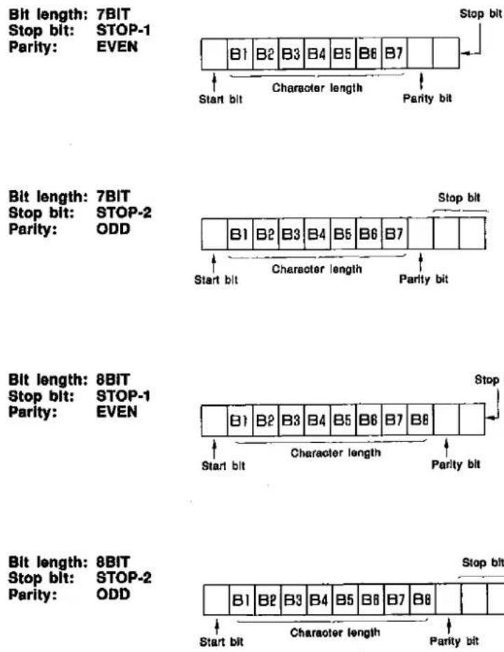
NOTES
[Note 1]
Character (data) length
This is the number of bits that configure the character data.
[Note 2]
Stop bit
Added to each character are the start bit which indicates the start of the data and the stop bit which indicates the end of the data. The start bit is fixed at 1 bit but the stop bit can be set to either 1 or 2 bits.
[Note 3]
Parity bit
The parity bit is added for checking transmission errors. When data is to be transmitted, the total number of ones for the character is made an even number or odd number of ones depending on the setting of this bit, and this is checked at the receiving end.
Total number of ones: odd number
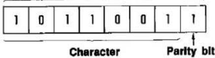
In the above case:
Parity error for an even number under parity check.
No parity error for an odd number under parity check.
[Note 4]
Baud rate (data transmission rate)
This is the volume of data which can be sent in one second. For instance, a rate of 2400 bps means that 2400 bits of data is sent in one second.


Recording the time code is a handy way of finding absolute positions on the tape.
■ Selecting the time code.
1

Select the time code mode.
REGEN: The regeneration mode is established. The VTR's clock value serves as the time code value, and the data and alarm count are written into the user's bit.
P FREE-RUN: The count starts from a preset time code value. The count continues to advance regardless of whether the VTR is recording or stopped. [See Note 1]
P REC-RUN: The count starts from a preset time code value. The count advances only during recording. [See Note 2]
■ Setting the time code (VITC) recording ON/OFF
2
Set the time code (VITC) recording ON or OFF. ON: The time code is recorded. OFF: The time code is not recorded.
[See Note 3]
■ Setting the time code (VITC) insertion lines
3

Set the lines at which the VITC code is to be inserted. 7H-22H: Select two insertion lines which are not side by side.
[See Note 4]
■ Setting the time code preset (default) value
4

Set the time code default value. 00:00:00:00: Set the values for hours/minutes/ seconds/frames.
- Any value from 00:00:00:00 to 23:59:59:24 can be set.
[Displaying the screens]
[Menu setting buttons]

■ Setting the user's bit preset value
5

Set the user's bit preset value.
00 00 00 00: Set an 8-digit alphanumeric string.
• Any of the following 16 alphanumerics can be used: 0, 1, 2, 3, 4, 5, 6, 7, 8, 9, A, B, C, D, E, F.
[See Note 5]
■ Time code
00:00:00:00
Hours : minutes : seconds : frames 1 second = Approx. 25 frames
Position where the time code is recorded on the tape

NOTES
[Note 1]
Free-running mode
In this mode, the time code is counted at all times. It is useful when recording durations in real time.
[Note 2]
Rec-running mode
In this mode, the time code is counted only while the VTR is in the recording mode. It is handy when ascertaining accurately an absolute position on the tape.
[Note 3]
VITC
This stands for vertical interval time code. It is a signal which is recorded on the vertical lines on the tape. It is recorded together with the video signals.
[Note 4]
Insertion line
This refers to the vertical line position where the VITC is recorded. Two lines are selected.
[Note 5]
User's bit
This is a code which the user sets as desired. It is useful for recording a control number or a tape's serial number, for instance, on the tape.
Checkpoints For Menu Setting
■ The menu screens appear only when the VTR is in the stop or eject status and when the recording lock switch is OFF. They do not appear when it is recording or playing back a tape, etc.
■ Internal timer recording is not activated unless the time and date have been set.
■ Whatever has been set on the menu screens is entered when the PROGRAM switch is returned to the "OFF" position.
■ How to select time modes
Refer to the table below and select the modes which fit the objective of the intended application.
| Mode | Recording enable time (in hours) | Video record-ing Interval (in seconds) | Audio record-ing | Camera switchover Interval (in seconds) | Type of tape travel | ||||
| 180-minute tape | 120-minute tape | 90-minute tape | TM1 | TM2 | |||||
| 3H | 3 | 2 | 1.5 | 1/50 | Possible | 1/25 | **1/25 | Continuous travel | |
| L12H | 12 | 8 | 6 | 0.1 | Possible | 0.2 | 0.1 | Continuous travel at low speed | |
| L24H | 24 | 16 | 12 | 0.18 | Possible | 0.36 | 0.18 | Continuous travel at low speed | |
| 24H | 24 | 16 | 12 | 0.18 | Not possible | 0.36 | 0.18 | Intermittent travel | |
| 48H | 48 | 32 | 24 | 0.34 | Not possible | 0.68 | 0.34 | Intermittent travel | |
| 72H | 72 | 48 | 36 | 0.5 | Not possible | 1.0 | 0.5 | Intermittent travel | |
| 84H | 84 | 56 | 42 | 0.58 | Not possible | 1.16 | 0.58 | Intermittent travel | |
| 120H | 120 | 80 | 60 | 0.82 | Not possible | 1.62 | 0.82 | Intermittent travel | |
| 180H | 180 | 120 | 90 | 1.22 | Not possible | 2.44 | 1.22 | Intermittent travel | |
| 240H | 240 | 160 | 120 | 1.62 | Not possible | 3.22 | 1.62 | termittent travel | |
| 480H | 480 | 320 | 240 | 3.22 | Not possible | 6.44 | 3.22 | termittent travel | |
| Note 000H | Man-ual | Approx. 180 | Approx. 120 | Approx. 90 | Approx. 1.0 | Not possible | — | — | Intermittent travel |
| 1 min. | 9,000 | 6,000 | 4,500 | 60 | Not possible | — | — | Intermittent travel | |
| 2 min. | 18,000 | 12,000 | 9,000 | 120 | Not possible | — | — | Intermittent travel | |
| 3 min. | 27,000 | 18,000 | 13,500 | 180 | Not possible | — | — | Intermittent travel | |
* The figures in the table apply when TM1 and TM2 for CAMERA SW TIMING on menu screen 4 have been set to 1 FRAME and 1 FIELD, respectively. To ascertain the camera switchover interval when TM1 and TM2 have been set to other timing values, multiply the timing setting by the figure given in the above table for the mode in question.
**1/25
Since the cameras cannot be switched over in 1-field units in the 3H mode, the switchover takes place at 1/25-second intervals.
Use 1/50-second as the basis for multiplication involving two or more fields. (For instance, with a 2 FIELD setting, multiply 1/50 by 2 which yields 0.04 sec.; with a 3 FIELD setting, multiple 1/50 by 3 which yields 0.06 sec.)
Note: The figures for 000H (1-shot recording) apply when the 1-shot recording time on menu screen 5 has been set to 1 field.
- The actual recording enable time will be slightly longer than the "Recording enable time" given in the above table although this will depend on the tape used.
For instance, it is possible to record for about 27 hours using a 180-minute tape in the 24H mode.
Helpful Functions
Applications
Series Recording 58
1-Shot Recording 60
Automatic Time Setting 64
Other Functions 66
Series Recording
(Model AG-6730 only)

The steps for continuous recording using several time lapse VTRs are described in this section.
1

Set this switch to "MENU."
• □ is no indication for AG-6040.
![[DISPLAY] MODE T/D CHARACTER WHITE POSITION L-UPPER TIME SELECT 24HOURS DATA ON TIME ON T-MODE ON](/content/2026/06/1329859/images/da5ef8a582b509ef36b20d9c15486699a142b0eb693e026c45e8dd4b71b861bc.jpg)
2

Press one of these buttons to display menu screen 2.
![((VTR MODE SELECT 1)) [REC T-MODE] OFF (TAPE IN) MODE STOP (TAPE END) MODE STOP ALARM IN STOP (EJECT OPERATION) MODE EJECT](/content/2026/06/1329859/images/488df434cf1ce163cd4e1f42bb90b4fce1679f64aa160c83b9d23acc2ff5d4f8.jpg)
3

Press this button to select "TAPE END MODE."
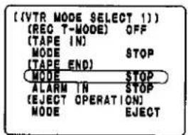
4

Press one of these buttons to set to "REW."

5

Press this button to select "TAPE END ALARM IN."
![[VTR MODE SELECT 1] [REQ T-MODE] OFF (TAPE IN) MODE STOP (TAPE END) MODE REW ALARM IN STOP (EJECT OPERATION) MODE EJECT](/content/2026/06/1329859/images/45659eed792f400d28ed432bc1462880ed2ed313a0d2a3b541aa14cf631ef2bd.jpg)

6
Press one of these buttons to set to "CONTINUE."
![((VTR MODE SELECT 1)) [REC T-MODE] OFF [TAPE IN] MODE STOP [TAPE END] MODE REN ALARM IN CONTINUE (EJECT OPERATION) MODE EJECT](/content/2026/06/1329859/images/891ad8b21e06bb01fe702cb42c6a24133b3ae844a4bb1f081245aeb44b708f5a.jpg)
7

Set this switch to "OFF."

■ Series recording with 2 or more time lapse VTRs
The second VTR starts recording as soon as the tape-end in the first VTR is detected.
■ Alternate recording with 2 VTRs
The second VTR starts recording as soon as the tape-end in the first VTR is detected.
The first VTR starts recording again as soon as the tape-end in the second VTR is detected.
NOTES
■ After having completed the settings, proceed with the regular recording operation using the first VTR.
■ Set the power switches of the second and subsequent VTRs to the "ON" position.
In order to prevent errors occurring in operation, it is recommended that the REC LOCK switch is set to "1" or "2."


The steps for 1-shot recording used for data files and animation, for instance, are described in this section.
1
Set this switch to "MENU."
• □ is no indication for AG-6040.
![[(DISPLAY)] MODE T/D CHARACTER WHITE POSITION L-UPPER TIME SELECT 24HOURS DATA ON TIME ON T-MODE ON](/content/2026/06/1329859/images/9399b149408872ce617d40403a0b257316168fc8c45f73b9b84c87c5acb6da3b.jpg)
2

Press one of these buttons to display menu screen 2.

3

Press this button to select "REC T-MODE."
![[ (VTR MODE SELECT 1) ] (REC T-MODE) OFF (TAPE IN) MODE STOP (TAPE END) MODE STOP ALARM IN STOP (EJECT OPERATION) MODE ELECT](/content/2026/06/1329859/images/b8ee4994397d1a4b93ec33e5c350354a40302aeba7c6160eb39e1d3e406a4c10.jpg)
4

Press one of these buttons to display "000H."
[See Note 1]
![[VTR_MODE_SELECT_1] [REG T-MODE] 000H (TAPE IN) MODE STOP (TAPE END) MODE STOP ALARM IN STOP (EJECT OPERATION) MODE EJECT](/content/2026/06/1329859/images/8a0e1a23efa12e133d44ce77576b5324f7377d97b61b543b1e5eb60f146b835e.jpg)
5
Press this button to display menu screen 5.
(This step applies to model AG-6730 only.)
![[ (1-SHOT REC) ] FIELD 1 INTERVAL 3MIN](/content/2026/06/1329859/images/b08929e3ddc2d0ff8864bd4de2948590551b3b396c552bc9633517c9fdfa6be5.jpg)

6

Press one of these buttons to select "FIELD."
(This step applies to model AG-6730 only.)
![[ (1-SHOT REC) ] FIELD 1 INTERVAL 3MIN](/content/2026/06/1329859/images/f418c01753da6488d36815617d029b1d8defd8059f7c62664c52b643dcc0062c.jpg)
7

Press one of these buttons to set the 1-shot recording time.
[See Note 2] (This step applies to model AG-6730 only.)
![[1-SHOT REC] FIELD 3 INTERVAL 3MIN](/content/2026/06/1329859/images/1f64a7e5824389be04b38c0578288521b34cee468efe3e779ed014533dd1ad94.jpg)
8
Press this button to select "INTER-VAL."
(This step applies to model AG-6730 only.)
![[ (1-SHOT REC) ] FIELD 3 INTERVAL 3MIN](/content/2026/06/1329859/images/e9ee71cc647c26811fe1ecfaf88000155592b71697bf4bb690110b204d0d03bc.jpg)
9

Press one of these buttons to set the interval time.
[See Note 3] (This step applies to model AG-6730 only.)

10

Set this switch to "OFF."
↓ (Continued overleaf)

NOTES
[Note 1]
When "REC T-MODE" on menu screen 2 is "OFF," the time mode can be set to "000H" also by pressing the TIME MODE button on the front sub panel.
[Note 2]
Each time the SET button is pressed, the time for recording one frame is successively changed as follows: 1 → 2 → 3 → 4 → 5 → 10 → 15 → 20 → 25 → 30 → 40 → 50 → 1 → 2 ... (Unit: field) (This time is fixed at 1 field for model AG-6040.)
[Note 3]
Each time the SET button is pressed, the interval time is successively changed as follows: 1 → 2 → 3 → 1 ... (Unit: minute) (This time is fixed at 3 minutes for model AG-6040.)


11
![PANASONIC AG-6040E - [Note 3] - 3](/content/2026/06/1329859/images/bb08d744107977f346bdd51b7b4b1815340c033cc910f5d326ea3efd5cbab2b1.jpg)
When this button is pressed, few shots are recorded and the VTR is set to the recording standby mode.
![PANASONIC AG-6040E - [Note 3] - 4](/content/2026/06/1329859/images/4998f3d177074cb7ec98862a09f28b28682fd37e12aef935bd41fc30c24b333a.jpg)
12
![PANASONIC AG-6040E - [Note 3] - 5](/content/2026/06/1329859/images/bbb4527c5144b070f985906734de098570bc4239c928c1ca6de73b34eb6fd78a.jpg)
When the button is pressed again, 1 shot is recorded and the VTR is set to the recording standby mode.
![PANASONIC AG-6040E - [Note 3] - 6](/content/2026/06/1329859/images/2fb127b2201a871eb31c0078832fe27cfea1b72cbb9ba98c19c2c8c03987bb0d.jpg)
13
■ One frame (shot) is recorded each time this button is subsequently pressed.
If the REC button is not pressed, one frame (shot) is recorded automatically when the interval time elapses.
14
![PANASONIC AG-6040E - [Note 3] - 7](/content/2026/06/1329859/images/2f8fe1367a9da0af006571e3d470127a54ec0faaac9ed787998db923202052fb.jpg)
Press this button to stop 1-shot recording.
15
![PANASONIC AG-6040E - [Note 3] - 8](/content/2026/06/1329859/images/aa9fe4c41a6614b8cdd4f798d39b5ef032bb4a9baf7e799f99b25d369314eaa4.jpg)
To release this mode, set to any position except "000H."
![[VTR MODE SELECT !] [REQ T-MODE] OFF [TAPE IN] MODE STOP [TAPE ENO] MODE STOP ALARM IN STOP [EJECT OPERATION] MODE EJECT](/content/2026/06/1329859/images/5b58835ec30f59684aa6e9136e67896f9e66defb892837d2c6f3e5389dceedd3.jpg)

■ 1-shot recording using a remote switch
Besides activating 1-shot recording by pressing the
REC button on the VTR's front panel, it is also possible to connect a remote switch and activate 1-shot recording from a distance by remote control.
- Ask your dealer to give you details about a remote switch.
• The ON time for the remote switch must be at least 100ms.
- An interval of at least 1 second is required to turn on the remote switch. Refer to page 74 for the signal levels.
NOTES
[Other notes]
- Refer to page 49 for the lengths of time during which recording can be performed in the 1-shot recording mode.
- In some cases, when playing back a portion of tape made with manual one-shot recording, the picture may not appear in colour.
Automatic Time Setting
(Model AG-6730 only)

Using an external switch, for instance, it is also possible to set this unit's time to any time setting.
With this unit serving as the master clock, it is possible set the time of other time lapse recorders (only Panasonic time lapse recorders equipped with a time adjust input connector).
1

Set this switch to "MENU."
- □ is no indication for AG-6040.
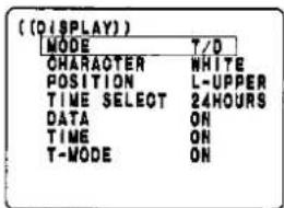
2
Press one of these buttons to display menu screen 3.
• □ is no Indica- tion for AG-6040.
![[VTR MODE SELECT 2] [POWER LOSS MEMORY] 88-8-8 88 [VIDEO] MODE AUTO IN LINE S-VHS REC ON (TIME ADJUSTING) SET TIME 9:00 OPERATION SLAVE](/content/2026/06/1329859/images/27618899cf44ca8811c1949db0f0ef3d2e61f90b4bf67d20cfd63e450538109b.jpg)
3

Press this button to select "TIME ADJUST SET TIME."
• □ is no indication for AG-6040.
![((VTR MODE SELECT 2)) (POWER LOSS MEMORY) *- * - * * : $ * * [VIDEO] MODE AUTO IN LINE S-VHS REG ON (TIME ADJUSTING) SET TIME 9:00 OPERATION SLAVE](/content/2026/06/1329859/images/607b8b0b79ffc85d5d16d5b34d30f1fa41b935b5938f604f987e9918eaf5ccce.jpg)
4

Press one of these buttons to set the time.
![[VTR MODE SELECT 2] [POWER LOSS MEMORY] $-$--3:$$ [VIDEO] MODE AUTO IN LINE S-VHS REC ON (TIME ADJUSTING) SET TIME 11:00 OPERATION SLAVE](/content/2026/06/1329859/images/bfcc2ac33a3f6ec3e5bb58153b96e45277aa25873da03db210012f7d5a8b2b45.jpg)
5

Press this button to select "TIME ADJUST OPERATION."
![[(VTR MODE SELECT 2)] [POWER LOSS MEMORY] 8:8-3-3:3:3 [VIDEO] MODE AUTO IN LINE S-VHS REC ON (TIME ADJUSTING) SET TIME 11:00 OPERATION SLAVE](/content/2026/06/1329859/images/68793d87c72f0b72b8241df1f3202ececea8e9c57f7c66b9902526a3e38f920f.jpg)

6

Press one of these buttons to select the time setting mode.
[See Note 1]
![((VTR MODE SELECT 2)) [POWER LOSS MEMORY] 11-12-13 14 [VIDEO] MODE AUTO IN LINE S-VHS REG ON [TIME ADJUSTING] SET TIME 11:00 OPERATION MASTER](/content/2026/06/1329859/images/99441b1cc39ed30193ad94f3b70e67375b9abd0272f24a967a86d71d437b6934.jpg)
7

Set this switch to "OFF."
NORMAL PICTURE
NOTES
[Note 1]
■ When SLAVE is selected:
When the rear panel's time adjust input terminal is shorted to ground, this VTR is set to the time which was set in step 4 and, at the same time, the pulses are output to the other VTRs.
■ When MASTER is selected:
Pulses are output to the other VTRs when this VTR is set to the time which was set in step 4.
Other Functions
Power restoration recording
When there was a power failure during recording, the VTR is automatically set to the recording mode provided that the power is restored within one month.
■ Immediately after the power has failed, the VTR is set to the tape protection mode so as to protect the video heads and tape.
■ The VTR status established after the power is restored depends on the status established prior to the power failure and on the recording mode, as follows.
| Mode\Status | Recording | Playback, stop, fast forward, rewind | Auto rewinding during auto repeat recording |
| Alarm | Recording | Stop | Recording after tape is rewound to its start |
| Internal timer | Resume the recording as per the settings of the internal timer. | ||
| External timer | Recording | Recording | Recording after tape is rewound to its start |
In the event of power failure lasting more than one month, recording will be forcibly started by the recorder in the 72H mode once the power has been restored if a tape has been loaded.
Automatic recording review function
This function conducts the recording review automatically when recording has been commenced from the stop mode.
First, recording is conducted for several seconds, and then what has been recorded is automatically reviewed. If, after a review of the recording, the proper video level was not achieved due to dirt on the heads or tape deterioration, the cassette mark (☐☐) flashes on the display tube and, at the same time, the automatic head cleaning operation is repeated 3 times. After this, recording is again conducted for several seconds, and then what has been recorded is automatically reviewed. If the result of the review is acceptable, the cassette mark stops flashing and the recording is commenced.
If the result of the review is not acceptable, the recording is commenced with the cassette mark still flashing. (See page 77)
Function setting method
Connect the 1-shot recording terminal to ground and short-circuit.
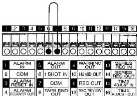
■ When the automatic recording review function is set, do not use the unit's 1-shot recording facility.
Connections
Equipment Connections 68
Terminal Connections 70
Terminal Signal Levels 74

flowchart
graph TD
    A["Equipment Connections"] --> B["RS-232C connector (option)"]
    B --> C["Personal computer"]
    C --> D["Use this to connect a personal computer for controlling the VTR."]
    D --> E["REMOTE (serial) connector (3 mm)"]
    E --> F["AG-A67 (option)"]
    E --> G["MIC IN jack (3 mm)"]
    G --> H["Microphone"]
    H --> I["This is used to connect the audio input signals from a microphone (with a 600Ω impedance)."]
    I --> J["GND"]
    J --> K["Terminal section (see page 70)"]
    K --> L["Video IN connectors (BNC)"]
    L --> M["Connect the external video input signal from a sequential switcher or other unit."]
    style A fill:#f9f,stroke:#333
    style B fill:#ccf,stroke:#333
    style C fill:#cfc,stroke:#333
    style D fill:#fcc,stroke:#333
    style E fill:#cff,stroke:#333
    style F fill:#ffc,stroke:#333
    style G fill:#fcc,stroke:#333
    style H fill:#ffc,stroke:#333
    style I fill:#fcc,stroke:#333
    style J fill:#cff,stroke:#333
    style K fill:#ffc,stroke:#333
    style L fill:#fcc,stroke:#333
AG-6730 only
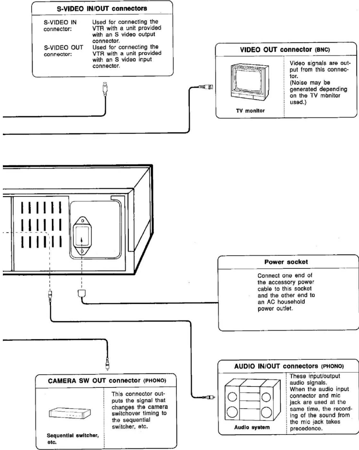
flowchart
graph TD
    A["S-VIDEO IN/OUT connectors"] --> B["S-VIDEO IN connector: Used for connecting the VTR with a unit provided with an S video output connector."]
    A --> C["S-VIDEO OUT connector: Used for connecting the VTR with a unit provided with an S video input connector."]
    D["VIDEO OUT connector (BNC)"] --> E["TV monitor"]
    D --> F["Power socket"]
    D --> G["AUDIO IN/OUT connectors (PHONO)"]
    H["CAMERA SW OUT connector (PHONO)"] --> I["Sequential switcher, etc."]
    H --> J["This connector outputs the signal that changes the camera switchover timing to the sequential switcher, etc."]
    K["Video signals are output from this connector.<br>(Noise may be generated depending on the TV monitor used.)"] --> L["TV monitor"]
    M["Power socket"] --> N["Connect one end of the accessory power cable to this socket and the other end to an AC household power outlet."]
    O["Audio system"] --> P["These input/output audio signals.<br>When the audio input connector and mic jack are used at the same time, the recording of the sound from the mic jack takes precedence."]
Terminal Connections
Notice for cables connected to terminals


—Press this part to connect or disconnect a cable.
Use wires with the specifications given below.
Solid
Wire
Stranded
Wire

0.4 - 1.2 mm (diameter)

-0.18 mm or more (diameter)
cross-section area: 0.3 - 1.25mm²
Note for Stranded Wire
Twist the end of the wire or solder it.
- Short circuiting may result if the end of a wire has not been twisted securely.

Terminal section of model AG-6040

External interfacing specifications
Example of lamp lighting with high signal.

■ Use devices with ratings which match the actual conditions of use.
Connections for alarm recording

flowchart
graph TD
    A["Alarm switch"] --> B["External Interface"]
    C["Alarm reset switch"] --> B
    D["1 ALARM IN"] --> E["2 COM"]
    E --> F["3 ALARM RESET IN"]
    F --> G["4 ALARM RECOVER OUT"]
    H["5 ALARM OUT"] --> I["6 1 SHOT IN"]
    I --> J["7 COM"]
    J --> K["8 TAPE END OUT"]
    L["9 WARNING OUT"] --> M["10 HUMD OUT"]
    N["11 REC OUT"] --> O["12 REC REVIEW OUT"]
    P["13 SERIES REC IN"] --> Q["14 SERIES REC OUT"]
    R["15 TIME ADJUST IN"] --> S["16 TIME ADJUST OUT"]
■ Alarm recording is commenced when the alarm switch is set ON.
■ Alarm recording is released when the alarm reset switch is set ON.
■ When alarm recording is started, the alarm lamp and buzzer are activated. Use a +12 V alarm lamp and buzzer.
Connections for 1-shot recording
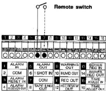
■ When the remote switch is set ON, one shot (frame) is recorded.
■ The ON time for the remote switch must be at least 200ms.
■ An interval of at least 1 second is required to turn on the remote switch.
Connections for tape-end output

flowchart
graph TD
    A["1 ALARM IN"] --> B["2 COM"]
    B --> C["3 ALARM RESET IN"]
    C --> D["4 ALARM RECOVER OUT"]
    E["5 ALARM OUT"] --> F["6 I SHOT IN"]
    G["9 WARNING OUT"] --> H["10 HUMID OUT"]
    I["13 SERIES REC IN"] --> J["14 SERIES REC OUT"]
    K["15 TIME ADJUST IN"] --> L["16 TIME ADJUST OUT"]
    M["Lamp/buzzer"] --> N["External interface"]
    style A fill:#f9f,stroke:#333
    style B fill:#f9f,stroke:#333
    style C fill:#f9f,stroke:#333
    style D fill:#f9f,stroke:#333
    style E fill:#f9f,stroke:#333
    style F fill:#f9f,stroke:#333
    style G fill:#f9f,stroke:#333
    style H fill:#f9f,stroke:#333
    style I fill:#f9f,stroke:#333
    style J fill:#f9f,stroke:#333
    style K fill:#f9f,stroke:#333
    style L fill:#f9f,stroke:#333
    style M fill:#f9f,stroke:#333
■ When the cassette tape reaches its end during recording, the alarm unit connected externally is activated.
Connections for auto OFF output

flowchart
graph TD
    A["1 ALARM IN"] --> B["5 ALARM OUT"]
    C["2 COM"] --> D["6 1 SHOT IN"]
    E["3 ALARM RESET IN"] --> F["7 COM"]
    G["4 ALARM RECOVER OUT"] --> H["8 TAPE END OUT"]
    B --> I["9 WARNING OUT"]
    D --> J["10 HUMID OUT"]
    F --> K["11 REC OUT"]
    H --> L["12 REC REVIEW OUT"]
    I --> M["13 SERIES REC IN"]
    J --> N["14 SERIES REC OUT"]
    K --> O["15 TIME ADJUST IN"]
    L --> P["16 TIME ADJUST OUT"]
    M --> Q["Lamp/buzzer"]
    N --> Q
    O --> Q
    P --> Q
    Q --> R["External interface"]
■ When a malfunction has occurred in this VTR, the alarm unit connected externally is activated.
In such a case, an error code will appear on the display (see page 77).
Connections for dew output (model AG-6730 only)

■ When dew (condensation) has formed inside this VTR, the alarm unit connected externally is activated.
In such a case, "O" will appear on the display (see page 76).
Connections for recording output (model AG-6730 only)

flowchart
graph TD
    A["1 ALARM IN"] --> B["2 COM"]
    B --> C["3 ALARM RESET IN"]
    C --> D["4 ALARM RECOVER OUT"]
    D --> E["5 ALARM OUT"]
    E --> F["6 1 SHOT IN"]
    F --> G["7 COM"]
    G --> H["8 TAPE END OUT"]
    H --> I["9 WARNING OUT"]
    I --> J["10 HUMID OUT"]
    J --> K["11 REC OUT"]
    K --> L["12 REC REVIEW OUT"]
    L --> M["13 SERIES REC IN"]
    M --> N["14 SERIES REC OUT"]
    N --> O["15 TIME ADJUST IN"]
    O --> P["16 TIME ADJUST OUT"]
    P --> Q["Lamp/buzzer"]
    Q --> R["External Interface"]
■ When the VTR is set to the recording mode, the alarm unit connected externally is activated.
Terminal Connections (Continued)
Connections for recording review (model AG-6730 only)
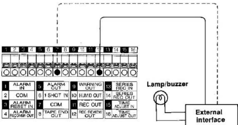
flowchart
graph TD
    A["1 ALARM IN"] --> B["2 COM"]
    B --> C["3 ALARM RESET IN"]
    C --> D["4 ALARM RECOVER OUT"]
    style A fill:#f9f,stroke:#333
    style B fill:#ccf,stroke:#333
    style C fill:#cfc,stroke:#333
    style D fill:#fcc,stroke:#333
    subgraph External interface
        L["Lamp/buzzer"] --> M["External interface"]
    end
■ The external unit is actuated if it was not possible for the proper video level to be obtained after the recording check operation due to dirt on the heads or deterioration of the tape. At the same time, the cassette mark (☐) on the display tube will flash. (See page 77)
Connections for series recording (model AG-6730 only)

flowchart
graph TD
    A["First VTR"] --> B["1 ALARM IN"]
    A --> C["2 COM"]
    A --> D["3 ALARM RESET IN"]
    A --> E["4 ALARM RECOVER OUT"]
    F["Second VTR"] --> G["1 ALARM IN"]
    F --> H["2 COM"]
    F --> I["3 ALARM RESET IN"]
    F --> J["4 ALARM RECOVER OUT"]
    B --> K["5 ALARM OUT"]
    C --> L["6 1 SHOT IN"]
    D --> M["7 COM"]
    E --> N["8 TAPE END OUT"]
    K --> O["9 WARNING OUT"]
    L --> P["10 HUMID OUT"]
    M --> Q["11 REC OUT"]
    N --> R["12 REC REVIEW OUT"]
    O --> S["13 SERIES REC IN"]
    P --> T["14 SERIES REC OUT"]
    Q --> U["15 TIME ADJUST IN"]
    R --> V["16 TIME ADJUST OUT"]
■ The second VTR starts recording as soon as the tape in the first VTR reaches its end.
■ The first VTR starts recording again as soon as the tape in the second VTR reaches its end.
■ When a third VTR is connected, the series output of the second unit is connected to the series input of the third unit.
Connections for time setting (model AG-6730 only)
■ Setting the time of another VTR using this VTR
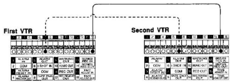
flowchart
graph TD
    A["First VTR"] --> B["1 ALARM IN"]
    A --> C["2 COM"]
    A --> D["3 ALARM RESET IN"]
    A --> E["4 ALARM RECORR OUT"]
    F["Second VTR"] --> G["1 ALARM IN"]
    F --> H["2 COM"]
    F --> I["3 ALARM RESET IN"]
    F --> J["4 ALARM RECORR OUT"]
    B --> K["5 ALARM OUT"]
    C --> L["6 ISHOT IN"]
    D --> M["7 COM"]
    E --> N["8 TAPE END OUT"]
    G --> O["9 ISHOT IN"]
    H --> P["10 HUMO OUT"]
    I --> Q["11 REC OUT"]
    J --> R["12 REC Review OUT"]
    K --> S["13 SCORED RED OUT"]
    L --> T["14 SCORED RED OUT"]
    M --> U["15 TIME ADJUST IN"]
    N --> V["16 TIME ADJUST OUT"]
Setting this VTR's time using the external switch

■ Setting the time of several VTRs using the external switch

flowchart
graph TD
    A["Switch"] --> B["First VTR"]
    B --> C["Second VTR"]
    subgraph First VTR
        D["ALARM IN"] --> E["ALARM OUT"]
        F["COM"] --> G["1 SHOT IN"]
        H["ALARM RESET IN"] --> I["COM"]
        J["ALARM RECOVER OUT"] --> K["TAPE END OUT"]
    end
    subgraph Second VTR
        L["ALARM IN"] --> M["ALARM OUT"]
        N["COM"] --> O["1 SHOT IN"]
        P["ALARM RESET IN"] --> Q["COM"]
        R["ALARM RECOVER OUT"] --> S["TAPE END OUT"]
        T["ALARM IN"] --> U["ALARM OUT"]
        V["COM"] --> W["1 SHOT IN"]
        X["ALARM RESET IN"] --> Y["COM"]
        Z["ALARM RECOVER OUT"] --> AA["TAPE END OUT"]
    end
- Set "TIME ADJUST OPERATION" on menu screen 3 of this VTR to "MASTER."
- When this VTR is set to the time which was set by "TIME ADJUST SET TIME" on menu screen 3, pulses are output and all the other VTRs are set to the time.
- Set "TIME ADJUST OPERATION" on menu screen 3 of this VTR to "SLAVE."
- When the TIME ADJUST IN terminal is connected to ground (COM) and short-circuited using an external switch, the time is set to what was set by "TIME ADJUST SET TIME" on menu screen 3.
- Set "TIME ADJUST OPERATION" on menu screen 3 of this VTR to "SLAVE."
- When the TIME ADJUST IN terminal is connected to ground (COM) and short-circuited using an external switch, the time is set to what was set by "TIME ADJUST SET TIME" on menu screen 3, and the other VTRs are also set to the time.
■ Other time lapse recorders which can be connected to this unit are limited to Panasonic models equipped with time setting terminals.
Terminal Signal Levels
| Name of terminal | Signal level | Remarks | |
| Alarm input | 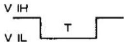 | V IL=0~0.6VT≥100mS | Ground input |
| Alarm reset input |  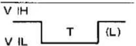 | V IH=4~5VV IL=0~0.6VT≥100mS | High/low input (H) or (L) can be selected on menu screen 4. |
| Alarm reset output | 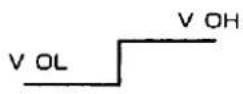 | V OH=5±0.5V(200Ω)V OL=0~0.6V(Max.3mA) | High output |
| Alarm output |  | V OH=11~13V(4700Ω)V OL=0~0.6V(Max.3mA) | High output |
| 1-shot recording input |  | V IL=0~0.5VT≥100mS | Ground input |
| Tape-end output |  Reset Reset | V OH=11~13V(4700Ω)V OL=0~0.6V(Max.3mA)T=approx.2s | Ground output |
| Auto OFF output |  | V OH=11~13V(4700Ω)V OL=0~0.6V(Max.3mA) | Ground output |
| Dew output (model AG-6730 only) | 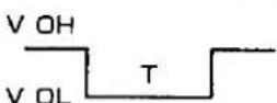 | V OH=4~5.5V(10KΩ)V OL=0~0.6V(Max.3mA) | Ground output |
| Recording output (model AG-6730 only) | 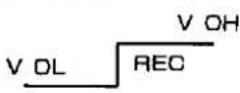 | V OH=11~13V(4700Ω)V OL=0~0.6V(Max.3mA) | High output |
| Recording check output (model AG-6730 only) |  | V OH=11~13V(4700Ω)V OL=0~0.6V(Max.3mA)OK when reset | Ground output |
| Series recording input (model AG-6730 only) | 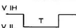 | V IL=0~0.6VT≥100mS | Ground input |
| Series recording output (model AG-6730 only) |  | V OL=0~0.6VT≥approx.700mS | Ground output |
| Time set input (model AG-6730 only) |  | V IL=0~0.6VT≥100mS | Ground input |
| Time set output (model AG-6730 only) |  | V OL=0~0.6VT=approx.1s | Ground output |
Precautions For Use
Dew ("δ") Display 76
Error Codes 77
Safety Precautions 78
Handling Precautions 79
Daily Inspections/Regular Inspections 80
Optional Accessories 82
Troubleshooting (Q&A) 84
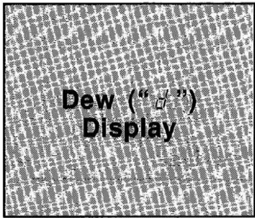
■ When dew forms inside the VTR, the " ' " mark appears on the display.
Wait a few hours until the "δ" mark is cleared before proceeding any further with operation.

“♂” refers to the first letter of the word “dew.”
Dew (or condensation) refers to the phenomenon whereby droplets of water form, for instance, on the window pane of a warm room in winter.
■ When dew has formed:
- "d" appears on the display.
- The VTR cannot be operated until "d" is cleared from the display. Wait until it is cleared.
- When dew forms with the power OFF; the power is automatically switched on and the "o" mark appears.
- If a cassette has been installed, it is ejected half-way.
- If a cassette has not been installed, one cannot be installed until " ^l " is cleared from the display.
■ When the dew status is released:
• The VTR is restored to the state where regular operation is possible.
- If a cassette was installed, it is set to the stop mode.
- If dew formed during recording, the VTR is reset to the recording mode after the dew status is released.
■ Take care even while dew is forming!
Dew normally forms gradually, and the "j" mark may not flash for the first 10 to 15 minutes of dew formation. If the room temperature or humidity has changed, wait 20 minutes or so before using the VTR.
■ Conditions conductive to dew-forming
- When the VTR or cassette is moved from one location to another where the temperature or humidity is significantly different from the original location
• Where the humidity is high - When the VTR or cassette is moved rapidly from a cool place to where the temperature or humidity is high
• A room immediately after it has been heated up

■ An error display appears on the display tube when a failure or malfunction has occurred in the unit. The error display indicated on the display denotes the nature of the failure or malfunction.
Take the remedial action described below.
■ Error codes

■ Cassette mark flashing error

When a malfunction occurs in the VTR, an error code appears on its display.
■ When an error code appears:
- An error code appears on the display.
- All operations are shut down when an error code appears on the display.
- If the error is not released even after taking the remedial action described below, switch off the power, disconnect the power cable from the power outlet, and contact your dealer immediately.
■ List of error codes
| Error code | Malfunction | Remedial action |
| E-2 | Malfunction in elevator section | These errors may occur if the video cassette has not been loaded properly. Try switching the power off and turning it back on again. |
| E-3 | Malfunction in loading section | |
| E-4 | Malfunction in cylinder section | These errors may occur if there is something wrong with the state of the video cassette. Try switching the power off and turning it back on again and replacing the video cassette. |
| E-5 | Malfunction in reel section | |
| E-6 | Incorrect tape tension | |
| E-7 | Malfunction in reel solenoid | Try switching the power off and turning it back on again. |
| E-R | Malfunction in audio recording circuitry | Try switching the power off and turning it back on again. |
■ Cassette mark flashing error
 Mark flashes Mark flashes | The cassette mark (○○) on the display tube flashes if it was not possible for the proper video level to be obtained after the recording review operation due to dirt on the heads or deterioration of the tape.VTR operation can still be continued but be sure to clean the heads or replace the cassette tape. |

Be sure to heed these safety precautions to prevent fire, electric shocks and injury.

Always hold the plug when connecting and disconnecting the power cable!

natural_image
Simple line drawing of a person standing near a wall with a cross mark, no text or symbols presentDo not bring the power cable near hot appliances!

natural_image
Simple line drawing of a mechanical or electrical component with no text or symbolsDo not place heavy objects on top of the power cable!

natural_image
Simple line drawing of a crab with a cross mark, no text or symbols presentDo not tamper with the power cable!

natural_image
Simple line drawing of a crossed-out box with plants and smoke (no text or symbols)Do not place a container with water on top of the VTR or bring it close to the VTR!

natural_image
Simple line drawing of a sandwich with steam and a crossed-out knife (no text or symbols)Do not block the ventilation holes!

natural_image
Simple line drawing of a drum with a cross mark and smoke, surrounded by flames (no text or symbols)Do not remove the cabinet panels!
Touching the inside parts is not only dangerous but can also lead to breakdowns. Do not poke metal objects inside the VTR.
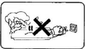
Do not use the VTR in a thunderstorm!
Disconnect the power plug as soon as possible.

Do not insert any object other than a video cassette into the cassette loading slot!

natural_image
Simple line drawing of a box with a 'X' mark and smoke, no text or symbols presentStop using the VTR If smoke, malodors or unusual sounds come from it!
Contact your dealer immediately.
Handling Precautions
Be sure to heed these handling precautions to prevent failures and breakdowns.

natural_image
Simple line drawing of a rocket with an X mark emerging from its side, no text or symbols present.When moving the VTR:
- Do not subject it to impact.
- Be sure to disconnect all the wires connected to it.
- Hold it securely so that it will not fall on your feet.

Do not spray insecticides or volatile substances onto the VTR!
These may cause discolouring or the paint to peel off.

natural_image
Cartoon character holding a rolling pin with a cross symbol (no text or numbers present)Do not place heavy objects on top of the VTR.
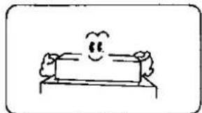
natural_image
Simple line drawing of a bench with a smiling face and limbs (no text or symbols)Install the VTR on a level and stable surface.

natural_image
Simple line drawing of a smiling sun above a box with a black cross at the base (no text or symbols)Avoid Instailing the VTR at a location which is exposed to direct sunlight.

natural_image
Simple line drawing of a hand pointing at a box with falling liquid, no text or symbols presentWipe off any dirt using a soft cloth.
- Dip the cloth into diluted neutral detergent and wipe off the dirt. Be sure to wipe the VTR dry afterwards.

Do not use benzene or paint thinners to clean this unit.
These may cause discolouring or the paint to peel off.
■ The top panel and rear parts will become quite warm after extended use. This is normal and not indicative of a failure or malfunction.
Daily Inspections/ Regular Inspections

This unit is designed to withstand prolonged use. However, do not forget to perform the daily and regular inspections.
■ Daily inspections
Turn on the power to all the units.
1
• Is the TV monitor showing the correct picture?
- Are the time and date set properly?
2

Slightly rewind the tape in a cassette used for recording on the previous day.
3

Press one of these buttons to set the time (hour) mode to "3H."
4
Press this button to monitor the pictures.
• Is the playback picture free from problems?
- Are the recorded time and date correct?
5
Try recording in the 3-hour mode.
- Play back the recording. Is there anything abnormal?

■ Regular inspections
• The regular inspections are performed by your dealer.
- This unit comes with a function (hour meter) which displays the number of hours that it has been used, and this display serves as a general guideline for the regular inspections.
- Depending on the total number of hours that the VTR has been used (the cylinder has turned), parts inside the unit must be replaced or cleaned.
- For further details, consult with your dealer.
6
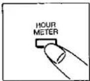
Press this but- ton.
The total number of hours now appears on the display.

NOTES
- If a problem has arisen after the daily inspection, refer to the "Troubleshooting Q&A" page, and try to remedy the cause of the problem.
If the malfunction still cannot be remedied, switch off the power, hold the power plug and disconnect the power cable from the power outlet, and consult your dealer. - Do not forget to perform the daily inspections particularly with auto repeat recording.
Optional Accessories
A variety of optional accessories are available to enable you to make the maximum use of this VTR's functions.
AG-A67 Remote Controller
This VTR can be operated by remote control instead of using its function buttons if the optional AG-A67 remote controller is connected to the remote connector on the VTR's rear panel.
■ The functions which can be controlled using the AG-A67 remote controller are listed below:
REC, REC REVIEW, REW, FF, PLAY, PAUSE/STILL, REV ADV, FWD ADV
■ Do not connect headphones, etc. to the REMOTE control input connector.

natural_image
Line drawing of a device with an attached cable and a separate panel, no text or symbols present.AG-IA670 RS-232C Interface Adaptor

natural_image
Technical line drawing of a device front panel with labeled components (no text or symbols)AG-IA670 RS-232C Interface adaptor
The functions listed below can be added by mounting the RS-232C interface board adaptor.
RS-232C communication functions
The VTR can be controlled using a personal computer. Menu screen 7 (RS-232C parameter settings) is added.
VITC time code recording/playback function
Time code signals can be recorded onto the tape. These come in handy for searches by locating absolute positions on the tape.
Menu screen 8 (time code settings) is added. Note:
The VITC time code cannot be recorded when video signal is not supplied.
Troubleshooting (Q&A)
| Trouble | Check | Remedy |
■ Power supply
| No power | • Has the power plug been disconnected from the outlet? | Connect the power plug properly. |
| • Is an external timer connected? | Operate the external timer and supply power to the VTR. |
Operation
| No operation no matter which function button is pressed. | Has an error code appeared on the display? | See page 77. |
| Has the "δ" mark appeared on the display? | See page 76. | |
| Is the recording mode set to INTERNAL TIMER? | Press the REC MODE button. | |
| Has the cassette been loaded properly? | Load it again properly. |
■ Recording
| No recording | • Has the "tab" on the cassette tape been broken out? | See page 36. |
| • Is the tape at its end? | Rewind it. | |
| • Has the PAUSE/ STILL button been pressed? | Release it. | |
| Recording cannot be stopped. | • Is the REC LOCK switch set to "1" or "2"? | Set the REC LOCK switch to "OFF." |
| No power restora-tion recording. | • Has the power failure lasted a month or more? | See page 66. |
| No internal timer recording. | • Have the time and date been set? | Complete the time/date settings.(See page 34) |
| Trouble | Check | Remedy |
■ Recording
| No auto repeat recording | • Is “TAPE END MODE” on menu screen 2 set to “REPEAT”? | Set to “REPEAT.” (See page 42) |
| No alarm recording. | • Is “MODE” on menu screen 4 set to any position other than “OFF”? | Set to any position other than “OFF.”(See page 46) |
| • Are the alarm switch connections complete? | Complete the connections.(See page 70) | |
| No buzzer at tape-end. | • Is “TAPE END MODE” on menu screen 2 set to “BUZZER”? | Set to “BUZZER.” (See page 42) |
■ Playback
| No playback | • Has a pre-recorded cassette been loaded? | Load the cassette properly. |
| Noise on playback screen. | • Any tracking deviation? | Press the TRACKING buttons to adjust the tracking. (See page 31) |
| • Dirty heads? | Clean the heads with the optional cleaning tape. If the problem is not remedied, consult your authorized dealer. | |
| • Old tape? | Replace with a new cassette tape. | |
| Playback picture shakes vertically. | • Does the vertical hold on the TV monitor need adjusting? | Adjust the vertical hold on the TV monitor. |
■ Menu screens
| No menu screens | Is the VTR in the stop or eject mode? | The menu screens appear only when the VTR is in the stop or eject mode. |
| Is the recording lock switch at the "OFF" position? | The menu screen will not appear if this switch is set to "1" or "2." |
■ Clock displays
| Time is not dis-played correctly. | Is the internal battery capacity still sufficient? | Keep the power supplied continuously for at least 40 hours. (See page 35) If the time is still not displayed correctly, the internal battery may have reached the end of its service life. |
Power Source:
Power Consumption:
220 V - 240 VAC, 50 - 60 Hz
Approx. 27 W
is the safety information.
General
Operating Temperature:
Operating Humidity:
Dimensions:
Weight:
Video Recording System:
Tape Speed:
Tape Format:
Recording Time:
FF/REW Time:
5^ C to 40^ C
35% to 80%
380(W) × 112(H) × 340(D) mm
Approx. 7.5 kg
2 rotary heads, Azimuth recording system, VHS/S-VHS formats
23.39 mm/s (3H mode)
S-VHS/VHS tape
3/L12/L24/24/48/72/84/120/240/480 hours and 1-shot mode
Approx. 3 min. (with 180-minute tape)
VIDEO
Television System:
Modulation System:
S-VIDEO Input(4P):
Video Input(BNC):
S-VIDEO Output(4P):
Video Output(BNC):
Horizontal Resolution:
CCIR Standard (625 lines, 50 fields)
PAL colour signal
Luminance;
Colour signal;
Y;
C;
1.0Vp-p, 75 ohms, unbalanced
Y;
C;
1.0Vp-p, 75 ohms, unbalanced
B/W mode;
400 lines(S-VHS)
Colour mode;
400 lines(S-VHS)
B/W mode;
Colour mode;
Frequency modulation recording
Converted subcarrier phase shift recording
1.0Vp-p, 75 ohms, unbalanced
0.3Vp-p, 75 ohms, unbalanced
ced
1.0Vp-p, 75 ohms, unbalanced
0.3Vp-p, 75 ohms, unbalanced
ced
320 lines(VHS)
400 lines(S-VHS)
240 lines(VHS)
400 lines(S-VHS)
more than 45 dB (3H mode)
more than 45 dB (3H mode)
AUDIO
Line Input (Phono):
Mic Input (3 mm):
Line Output (Phono):
Track:
S/N:
Frequency Response:
-10 dBv, 47 kohms, unbalanced
-60 dBv, 600 ohms to 4.7 kohms, unbalanced
-8 dBv, 600 ohms, unbalanced
1 track
43 dB (3H mode)
50 Hz to 10,000 Hz (3H mode)
Standard accessory
Power Cord:
×1
Weight and dimensions shown are approximate.
Specifications are subject to change without notice.
Power Source:
Power Consumption:
220 V - 240 VAC, 50 - 60 Hz
Approx. 22 W
is the safety information.
General
Operating Temperature: 5°C to 40°C
Operating Humidity: 35% to 80%
Dimensions: 380(W) x 112(H) x 340(D) mm
Weight: Approx. 7.5 kg
Video Recording System: 2 rotary heads, Azimuth recording system, VHS formats
Tape Speed: 23.39 mm/s (3H mode)
Tape Format: VHS tape
Recording Time: 3/L12/L24/24/48/72/84/120/240/480 hours and 1-shot mode
FF/REW Time: Approx. 3 min. (with 180-minute tape)
VIDEO
Television System: CCIR Standard (625 lines, 50 fields)
PAL colour signal
Modulation System: Luminance;
Frequency modulation recording
Colour signal; Converted subcarrier phase shift recording
Video Input(BNC): 1.0Vp-p, 75 ohms, unbalanced
Video Output(BNC): 1.0Vp-p, 75 ohms, unbalanced
Horizontal Resolution: B/W mode; 320 lines
Colour mode; 240 lines
S/N: B/W mode; more than 45 dB (3H mode)
Colour mode; more than 45 dB (3H mode)
AUDIO
Line Input (Phono): -10 dBv, 47 kohms, unbalanced
Mic Input (3 mm): -60 dBv, 600 ohms to 4.7 kohms, unbalanced
Line Output (Phono): -8 dBv, 600 ohms, unbalanced
Track: 1 track
S/N: 43 dB (3H mode)
Frequency Response: 50 Hz to 10,000 Hz (3H mode)
Standard accessory
Power Cord: ×1
Weight and dimensions shown are approximate.
Specifications are subject to change without notice.
Matsushita Electric Industrial Co., Ltd.
Central P.O. Box 288, Osaka 530-8691, Japan
Printed in Japan
VQT4864-2
S0992H5078-800①



- Operating Instructions
- Model AG-6730/6040 E
- Time Lapse Recorder
- Caution for AC Mains Lead
- FOR YOUR SAFETY PLEASE READ THE FOLLOWING TEXT CAREFULLY.
- FOR U.K. ONLY
- How to replace the fuse
- IMPORTANT
- ■ THIS APPARATUS MUST BE EARTHED.
- ■ DO NOT REMOVE PANEL COVER BY UNSCREWING.
- CAUTION:
- WARNING:
- Features
- Highly reliable IQ (intelligent quest) mechanism
- S-VHS system with high picture quality
- Multiple-function recording modes
- Other Features
- Front Panel
- Sub Panel
- For Swedish and Danish Customers
- Basic First Steps For Operation
- ■ Installing the cassette
- ■ Ejecting the cassette
- ■ Recording
- ■ Playback
- ■ Stop
- ■ Fast forwarding/rewinding
- ■ Search forward/search reverse
- ■ Temporarily suspending recording
- ■ Still-picture playback
- ■ Frame advance/reverse playback
- NOTES
- [Note 1]
- [Note 2]
- [Note 3]
- [Auto head cleaning function]
- (Continued)
- ■ Monitoring the recording
- ■ Adjusting the tracking
- ■ Adjusting the picture quality
- ■ Bringing up the menu screen
- ■ Bringing up the time setting display
- ■ Selecting the recording mode
- ■ Locking the recording
- ■ Selecting the time mode
- ■ Switching between the time and tape counter display
- ■ Resetting the tape counter
- [Note 4]
- 1
- 2
- 3
- 4
- 5
- ■ Recommended tapes
- [Note 5]
- [Note 6]
- [Other notes]
- Sensor (emergency) recording mode
- Alarm memory recall function
- Alarm number:
- Internal Timer Recording
- Daily (every day) timer
- ■ Search playback (search forward/search reverse)
- ■ Alarm search procedure
- Operating precautions
- Accidental erasure prevention tab
- Menu Screens
- Set the switch to "MENU."
- ■ Menu screen 1 (screen display settings)
- ■ Menu screen 2 (VTR mode settings 1)
- ■ Menu screen 3 (VTR mode settings 2)
- ■ Menu screen 4 (alarm recording mode settings)
- ■ Menu screen 5 (1-shot recording mode settings) (model AG-6730 only)
- ■ Menu screen 6 (internal timer recording mode settings)
- ■ The menu screens below appear only when the optional RS-232C Interface Adaptor AG-IA670 is installed.
- ■ Menu screen 7 (RS-232C parameter settings)
- ■ Menu screen 8 (time code settings)
- Lap time display screen
- Page count display screen
- ■ Recording time mode selection
- ■ Selection of operation when cassette is installed
- ■ Selection of operation at tape-end
- ■ Setting auto rewind function release when an alarm Input is generated
- ■ Selection of cassette EJECT button
- Linear slow recording
- Time lapse recording
- Automatic recording mode
- Auto rewind function
- Auto repeat recording function
- ■ Power loss memory display
- ■ Selecting the video signal mode
- ■ Selecting the input video signal (model AG-6730 only)
- ■ Setting the S-VHS recording mode (model AG-6730 only)
- ■ Time adjust function time setting (model AG-6730 only)
- ■ Time adjust function selection (model AG-6730 only)
- MASTER mode
- ■ Selecting the alarm recording time mode
- ■ Setting the alarm recording duration
- ■ Buzzer ON/OFF
- ■ Setting the repeat-in function
- ■ Selecting the alarm reset pulse acceptance level
- ■ Setting the timing
- ■ Selecting the camera switchover mode
- Menu Screen 5
- ■ Selecting the 1-shot recording time
- Setting the interval time for 1-shot recording
- For model AG-6040
- Menu Screen 6
- (Internal timer recording mode settings)
- ■ Internal timer mode ON/OFF
- ■ Setting the timer recording start time
- ■ Setting the timer recording end time
- ■ Setting the recording time mode
- ■ Weekly timer recording
- ■ Daily timer recording
- ■ Using the weekly and daily timers in combination
- [Notes]
- RS-232C
- ■ Selecting the time code.
- Select the time code mode.
- ■ Setting the time code (VITC) recording ON/OFF
- ■ Setting the time code (VITC) insertion lines
- ■ Setting the time code preset (default) value
- ■ Setting the user's bit preset value
- ■ Time code
- Checkpoints For Menu Setting
- Helpful Functions
- Applications
- Series Recording
- ■ Series recording with 2 or more time lapse VTRs
- ■ Alternate recording with 2 VTRs
- Automatic Time Setting
- 11-12-13 14
- Other Functions
- Power restoration recording
- Automatic recording review function
- Function setting method
- Connections
- Terminal Connections
- Notice for cables connected to terminals
- Terminal section of model AG-6040
- External interfacing specifications
- Connections for alarm recording
- Connections for 1-shot recording
- Terminal Connections (Continued)
- Connections for time setting (model AG-6730 only)
- Terminal Signal Levels
- Precautions For Use
- ■ When dew has formed:
- ■ When the dew status is released:
- ■ Take care even while dew is forming!
- ■ Conditions conductive to dew-forming
- ■ When an error code appears:
- Handling Precautions
- When moving the VTR:
- Do not spray insecticides or volatile substances onto the VTR!
- Wipe off any dirt using a soft cloth.
- Do not use benzene or paint thinners to clean this unit.
- Daily Inspections/ Regular Inspections
- ■ Daily inspections
- ■ Regular inspections
- Press this but- ton.
- Optional Accessories
- AG-A67 Remote Controller
- RS-232C communication functions
- VITC time code recording/playback function
- Troubleshooting (Q&A)
- General
- VIDEO
- AUDIO
- Standard accessory
Marque : PANASONIC
Modèle : AG-6040E
Catégorie : Caméra de surveillance