
NV-FS100B - Magnétoscope PANASONIC - Notice d'utilisation et mode d'emploi gratuit
Retrouvez gratuitement la notice de l'appareil NV-FS100B PANASONIC au format PDF.


| Type de produit | Magnétoscope VHS |
| Marque | Panasonic |
| Modèle | NV-FS100B |
| Dimensions (L x H x P) | 430 x 88 x 340 mm |
| Poids | 4,5 kg |
| Alimentation | 220-240 V, 50 Hz AC |
| Consommation électrique | 24 W |
| Fonctions principales | Lecture et enregistrement VHS, recherche visuelle, programmation timer, arrêt automatique |
| Connectivité | Péritel (SCART), antenne RF, entrée/sortie audio/vidéo |
| Têtes vidéo | 4 têtes |
| Modes de lecture | SP, LP, EP |
| Télécommande | Incluse, infrarouge |
| Programmation | Programmateur hebdomadaire avec horloge intégrée |
| Entretien et nettoyage | Nettoyer les têtes vidéo avec une cassette de nettoyage, dépoussiérer le boîtier |
| Sécurité | Débrancher l'appareil avant tout nettoyage, ne pas exposer à l'humidité |
| Pièces détachées et réparabilité | Télécommande, câbles, courroies, têtes vidéo disponibles auprès de revendeurs spécialisés |
| Informations générales | Appareil de salon pour la lecture et l'enregistrement de cassettes VHS |
FOIRE AUX QUESTIONS - NV-FS100B PANASONIC
Questions des utilisateurs sur NV-FS100B PANASONIC
0 question sur cet appareil. Repondez a celles que vous connaissez ou posez la votre.
Poser une nouvelle question sur cet appareil
Téléchargez la notice de votre Magnétoscope au format PDF gratuitement ! Retrouvez votre notice NV-FS100B - PANASONIC et reprennez votre appareil électronique en main. Sur cette page sont publiés tous les documents nécessaires à l'utilisation de votre appareil NV-FS100B de la marque PANASONIC.
MODE D'EMPLOI NV-FS100B PANASONIC
1990
Panasonic
Video Cassette Recorder
NV-FS100B
Operating Instructions
CONTENTS
Page
3 CAUTIONS
4 CONTROLS AND COMPONENTS
8 INFRA-RED REMOTE CONTROLLER AND DIGITAL SCANNER
11 S-VHS FORMAT
11 S (SEPARATE)-VIDEO SOCKET, INSTALLATION
12 INSTALLATION
13 TUNING THE TV SET TO THE VIDEO PLAYBACK CHANNEL
14 SETTING THE TUNER IN THE VTR
15 SETTING THE CLOCK TO THE PRESENT TIME
17 THE VIDEO CASSETTE
18 PLAYBACK
26 RECORDING FROM A TV BROADCAST SIGNAL
28 NICAM SYSTEM
29 HI-FI AUDIO SYSTEM
30 USING THE VTR AS A HI-FI AUDIO RECORDER
31 SUPER OTR FUNCTION (ONE-TOUCH TIMER RECORDING)
33 TIMER RECORDING
39 VHS INDEX SEARCH SYSTEM
42 VHS ADDRESS SEARCH SYSTEM
46 INTRO SCAN FUNCTION
47 TIME SEARCH
48 CAMERA RECORDING
49 DUBBING (COPYING)
52 INSERT EDITING
53 AUDIO DUBBING
54 BEFORE REQUESTING SERVICE
Cover SPECIFICATIONS
Back
IMPORTANT
Your attention is drawn to the fact that recording of pre-recorded tapes or discs or other published or broadcast material may infringe copyright laws.
WARNING
TO REDUCE THE RISK OF FIRE OR SHOCK HAZARD, DO NOT EXPOSE THIS EQUIPMENT TO RAIN OR MOISTURE.
This apparatus was produced to BS 800:1983.
FOR YOUR SAFETY
■ DO NOT REMOVE OUTER COVER.
To prevent electric shock, do not remove cover. No user serviceable parts inside. Refer servicing to qualified service personnel.
■ AC MAINS LEAD CONNECTION
The wires in the mains lead of this apparatus are coloured in accordance with the following code.
Important

As the colours of the wires in the mains lead may not correspond with the coloured markings identifying the terminals in your plug proceed as follows: The wire which is coloured BLUE must be connected to the terminal which is marked with the letter N or coloured BLACK. The wire which is coloured BROWN must be connected to the terminal which is marked with the letter L or coloured RED.

is the safety information.
HQ (High Quality) Picture System
Video recorders carrying the HQ symbol mark feature the new VHS High Quality Picture System. This system assures complete compatibility with VTRs that use the conventional VHS system.

CAUTIONS
Please read these cautions before you operate this VTR.
Cassette Compartment Door
When first unpacking the unit, you may notice that the cassette compartment door is partially open. This condition is due to the operation of a safety device designed to protect the unit from vibration during shipment; it is not a malfunction. When the AC mains lead is connected to a mains outlet, the door will return to its original position.
Avoid Sudden Changes in Temperature
If the VTR is suddenly moved from a cold place to a warm place, moisture may form on the tape and inside the VTR.
Humidity and Dust
Avoid places where there is high humidity or much dust, which may cause damage to internal parts.
Do Not Obstruct the Ventilation Holes
The ventilation holes prevent abnormal increase in temperature. Do not block or cover these holes. Especially avoid covering the holes with soft materials such as cloth or paper.
Keep away from High Temperature
Keep the VTR away from extreme direct heat such as direct sunlight, heating radiators, or closed automobiles.
Keep Magnets away
Never bring a magnet or magnetized object near the VTR because it will adversely affect the performance of the VTR.
No Fingers or Other Objects Inside
Touching internal parts of this VTR is dangerous, and may cause serious damage to the VTR. Do not attempt to disassemble the VTR. There are no user serviceable parts inside.
Keep Water away
Keep the VTR away from flower vases, tubs, sinks, etc. CAUTION: If liquids are spilled into the VTR, serious damage could occur. If you spill any liquid into the VTR, consult qualified service personnel.
Cleaning the VTR
Wipe the VTR with a clean, dry cloth. Never use cleaning fluid, or other chemicals. And do not use compressed air to remove dust.
Stacking
Place the VTR in a horizontal position, and do not place anything heavy on it.
Video Head Clogging
The video heads are the means by which the recorder places picture signals on the tape during recording, and reads picture signals from the tape during playback. If these heads become dirty and clogged from long use, the signals can no longer be recorded correctly, and the playback picture will be distorted accordingly. This is the case, for example, during the playback of a tape, the sound is reproduced normally, but no picture is seen, or the picture is greatly distorted. When such a symptom case occurs have the recorder checked by qualified service personnel.
Lightning
To avoid damage by lightning, disconnect the aerial plug from the VTR.
Condensation may forms in the VTR If:
●The VTR is in a room where the heater has just been turned on.
●The VTR is in a room with steam or high humidity.
●The VTR is brought from cold surroundings into a well-heated room.
●The VTR is suddenly brought from cool surroundings, such as an air-conditioned room or car, to a place which is hot and humid.
Note:
Do not operate the VTR for at least 1 hour if any of the above conditions occur.
This VTR does not incorporate a dew sensor.
CONTROLS AND COMPONENTS
FRONT

| No. | Description | Page |
| 1 | Noise Filter/Edit Selector | 23 |
| 2 | Audio Rec Level Control Selector | 26 |
| 3 | MPX Filter Switch | 30 |
| 4 | Hi-Fi/Normal Mix Switch | 52 |
| 5 | Digital Tracking Selector | 24 |
| 6 | Nicam/Mono Switch | 28 |
| 7 | Tape Select Switch | 24 |
| 8 | S-VHS Selector | 11 |
| 9 | Simulcast Switch | 29 |
| 10 | Input Signal Selector | 14 |
| 11 | VTR On/Off Switch with Indicator | 13 |
| 12 | Headphones Output Level Control | 30 |
| 13 | Picture Sharpness Control | 18 |
| 14 | Hi-Fi Rec Level Controls | 27 |
| 15 | Cassette Compartment | 17 |
| 16 | Control Panel Open Button | 17 |
| 17 | S-VHS Indicator | 11 |
| 18 | Infra-red Remote Control Receiver | 8 |
| 19 | Multi-Function Display | 6 |
| 20 | Audio Recording Mode Indicators | 28 |
| 21 | Jog/Shuttle Indicator | 20 |
| 22 | Jog/Shuttle Button | 20 |
| 23 | Microphone Input Socket | 53 |
| 24 | Headphones Socket | 30 |
| 25 | Jog Dial | 21 |
| 26 | Shuttle Ring | 20 |
| 27 | Side Panel (Removable) | — |
| No. | Description | Page |
| 28 | Digital Tracking Indicator | 24 |
| 29 | Address Indicator | 42 |
| 30 | Renumber Indicator | 45 |
| 31 | Audio Dubbing Indicator | 53 |
| 32 | Insert Editing Indicator | 52 |
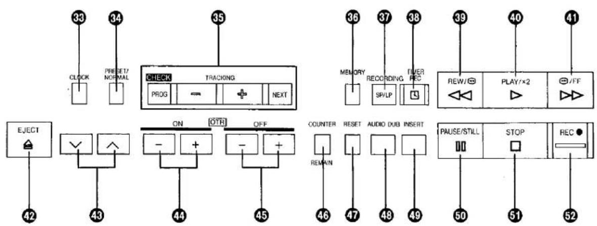
| 33 | Clock Button | 15 |
| 34 | Preset/Normal Button | 14 |
| 35 | Timer Controls | 33 |
| 36 | Memory Button | 14 |
| 37 | Tape Speed Button | 27 |
| 38 | Timer Record Button | 34 |
| 39 | Rewind ◀◀/Review [→] Button | 18 |
| 40 | Play/×2 Button (▶) | 18 |
| 41 | Fast Forward ▶▶/Cue [→] Button | 18 |
| 42 | Eject Button (▲) | 17 |
| 43 | Channel Selection Up and Down Buttons | 14 |
| 44 | OTR On Buttons | 31 |
| 45 | OTR Off Buttons | 31 |
| 46 | Counter/Remaining Tape Time Selector | 24 |
| 47 | Reset Button | 25 |
| 48 | Audio Dubbing Button | 53 |
| 49 | Insert Editing Button | 52 |
| 50 | Pause/Still Button (■) | 18 |
| 51 | Stop Button (■) | 18 |
| 52 | Record Button (●) | 26 |
CONTROLS AND COMPONENTS (CONT'D)
Multi-Function Display

| No. | Description | Page |
| 18 | Memory Indicator | 25 |
| 19 | Counter Mode Indicator | 25 |
| 20 | Tape Speed Indicator | 27 |
| 21 | Audio Output Mode Indicators | 29 |
| No. | Description | Page |
| 1 | Audio Level Meters | 27 |
| 2 | Timer Programme Number | 33 |
| 3 | Channel Display | 14 |
| 4 | Cassette-in Indicator | 17 |
| 5 | Tape Running Display | 18 |
| 6 | Timer Recording Indicator | 34 |
| 7 | Double Speed Indicator | 18 |
| 8 | Recording Indicator | 26 |
| 9 | OTR Indicator | 31 |
| 10 | Date Display | 15 |
| 11 | Position Indicator | 14 |
| 12 | Erase Indicator | 41 |
| 13 | Write Indicator | 40 |
| 14 | Remaining Tape Time Indicator | 24 |
| 15 | Tape Counter Indicator | 23 |
| 16 | Search Indicator | 25 |
| 17 | Repeat Indicator | 22 |
REAR

| No. | Description | Page |
| 1 | RF Output Socket | 11 |
| 2 | Editing Control Socket | 49 |
| 3 | Audio Input Sockets | 12 |
| 4 | Video Input Socket | 48 |
| 5 | Audio Output Sockets | 11 |
| 6 | Video Output Socket | 12 |
| 7 | RF Input Socket | 11 |
| 8 | RF Signal Level Switch | 13 |
| 9 | Synchro Edit Socket | 51 |
| 10 | AV Socket | 12 |
| 11 | Normal/Y/C Selector | 11 |
| 12 | S-Video Input Socket | 49 |
| 13 | S-Video Output Socket | 11 |
| 14 | Comb Filter/Test Signal Switch | 13 |
| 15 | AC Mains Lead Socket | 11 |
10 Connections of the AV Socket

| NOR | Y/C |
| 1 AUDIO OUTPUT CH2 (R) | 1 AUDIO OUTPUT CH2 (R) |
| 2 AUDIO INPUT CH2 (R) | 2 AUDIO INPUT CH2 (R) |
| 3 AUDIO OUTPUT CH1 (L) | 3 AUDIO OUTPUT CH1 (L) |
| 4 AUDIO GND | 4 AUDIO GND |
| 5 No connection | 5 No connection |
| 6 AUDIO INPUT CH1 (L) | 6 AUDIO INPUT CH1 (L) |
| 7 No connection | 7 No connection |
| 8 SWITCHING VOLTAGE | 8 SWITCHING VOLTAGE |
| 9 No connection | 9 No connection |
| 10 No connection | 10 No connection |
| 11 No connection | 11 No connection |
| 12 No connection | 12 No connection |
| 13 No connection | 13 No connection |
| 14 No connection | 14 No connection |
| 15 No connection | 15 C OUT |
| 16 No connection | 16 No connection |
| 17 VIDEO GND | 17 VIDEO GND |
| 18 No connection | 18 No connection |
| 19 VIDEO OUTPUT | 19 Y OUT |
| 20 VIDEO INPUT | 20 VIDEO INPUT |
| 21 GND | 21 GND |
Connections of the S-Video Socket:

INFRA-RED REMOTE CONTROLLER AND DIGITAL SCANNER

① VTR On/Off Button
② Clock Counter Selector
③ Audio Output Selector
4 Remaining Tape Time Button
⑤ Memory/Repeat/Search Button
6 Reset Button
7 Blank Search Button
⑧ Time Search Button
9 Record Buttons (●)
10 Rewind ◀◀/Review ←Button
⑪ Pause/Still Button (Ⅱ)
12 Write Button
13 Index Button
14 Address Button
15 Jog/Shuttle On/Off Button
16 Jog/Shuttle Indicator
17 Jog Dial
18 Shuttle Ring
19 Channel Mode Indicator
20 Channel Mode On/Off Button
21 Renumber Button
22 Erase Button
23 Fast Forward ▶▶/Cue ▶▶ Button
24 Play/×2 Button (▶)
25 Still Advance Button (▶)
26 Stop Button (■)
27 Programme Position (Channel) Selector Buttons
28 Monitor Button

① Transmit Button
② Bar Code Reading Section
③ Digital Scanner On/Off Switch
④ Bar Code Reader Display

① Date Display
② Start Time Display
3 End Time Display
4 Channel Display
⑤ Check Indicator
⑤ Transmitting Section
How to Operate the Digital Scanner
Set the Digital Scanner On/Off Switch to "ON".
- If no operation is performed for more than 25 seconds (4 minutes during setting of the clock time), the scanner will automatically switch over to the power-saving standby condition and the lamp will go off. (In this case, if bar codes have already been read but not yet transmitted to the VTR, the data will be cancelled.)
- When the Digital Scanner On/Off Switch is set to "ON" but the lamp is not lit, set the switch to "OFF" and then to "ON" again.
Tracing the Bar Codes
(A) Place the Digital Scanner vertically on the Small Box.
(B) Trace the bar code quickly in the direction of the arrow.

●Treat the Programming Sheet with care. If the sheet gets dirty or scratched, the bar code reading may become impossible.
- Protect the Digital Scanner from strong shocks and vibration. Keep it away from water and places with high temperature and humidity.
- If the bar code is traced slowly, it cannot be read correctly.
- When there is no "Beep" sound, the reading of the bar code is incomplete. Trace the bar code again.
- When using the Programming Sheet, put it on flat surface: Reading the bar codes while holding it in your hand or bending it, may result in incorrect operation.
- Do not deviate from the bar code, nor stop tracing halfway.
- Do not slant the scanner to trace the bar code.
INFRA-RED REMOTE CONTROLLER AND DIGITAL SCANNER (CONT'D)
Power Source for the Remote Controller (Digital Scanner)
The Remote Controller is powered by three IEC "R6" (Digital Scanner: 4IEC "R03") size batteries. The life of the batteries is about one year, however, it depends on the frequency of use. Inspect and if necessary, replace the batteries once a year.
CAUTION FOR BATTERY REPLACEMENT
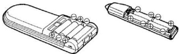
- Load the new batteries with their polarities (⊕ and ⊖) aligned correctly.
- Do not apply heat to batteries, or internal short-circuit may occur.
- If you do not intend to use the Remote Controller or Digital Scanner for a long period of time, remove the batteries and store them in a cool and dry place.
- Remove spent batteries immediately and dispose of them.
- Do not use an old and a new batteries together. (Also never use an alkaline battery with a manganese battery.)
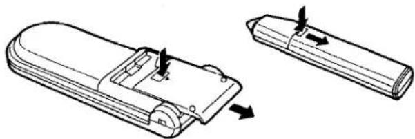
Load the batteries as follows:
① Remove the battery compartment lid.
natural_image
Technical line drawing of a device with two views: top view showing internal components and side view with arrows indicating movement (no text or symbols)② Place the batteries in the battery compartment as indicated inside the battery compartment.
natural_image
Technical line drawings of two battery modules with charging terminals (no text or symbols)③ Replace the lid.

natural_image
Diagram of a battery pack assembly showing internal components and battery casing (no text or labels)Note:
- The infra-red beam should be transmitted directly at the Infra-red Remote Control Receiver on the front of the VTR.
● Direct sunlight may interfere with the beam. - The lightsensing angle of the Infra-red Remote Control Receiver in the VTR is about 30° for each side from the centre.
●The unit should be used within a range of about 7 meters from the front of the VTR.
Recommendation
To save battery power, make sure to set the Digital Scanner On/Off Switch to "OFF" after using the Digital Scanner. When the batteries are exhausted, the bar code reading can no longer performed.
S-VHS FORMAT
This VTR uses the S-VHS format that makes it possible to obtain high resolution and high picture quality by using the high-performance S-VHS video cassette tapes.
When making a recording on an S-VHS cassette tape, select the desired recording format with the S-VHS Selector.

S-VHS Selector
ON: The recording will be made in the S-VHS format.
●The S-VHS Indicator lights up.
OFF: The recording will be made in the VHS format. ●The S-VHS indicator does not light up. (It is possible to make a recording on an S-VHS cassette tape in the VHS format, for example, in order to play back the tape on another VHS VTR.)
Using VHS Cassettes
The recording is made in the VHS format irrespective of the position to which the S-VHS Selector is set.
Playback of S-VHS and VHS Cassettes
It is not necessary to operate the S-VHS Selector.
- Cassette tapes recorded in the S-VHS format are automatically played back in the S-VHS format and tapes recorded in the VHS format are automatically played back in the VHS format.
When an S-VHS tape which was recorded in the VHS format is played back, the S-VHS Indicator does not light up.
When a tape which was recorded in the S-VHS format is played back on a conventional VHS VTR, it is not possible to obtain playback picture.
S (SEPARATE)-VIDEO SOCKET, INSTALLATION
The conventional video sockets of VTRs output (input) a combination of the luminance signal (Y) and color signal (C) which are recorded on the video tape. The new S (Separate)-Video Socket allows separate transmission of these two signals to a TV set or separate input of these two signals in order to obtain clearer pictures.
The connection with the S-Video Cable can also be used for playback of a tape that was recorded in the conventional VHS system. The "S" in the "S-Video Socket" stands for "SEPARATED Y/C" not for "S-VHS".
Connection to a TV Set with S-Video Socket
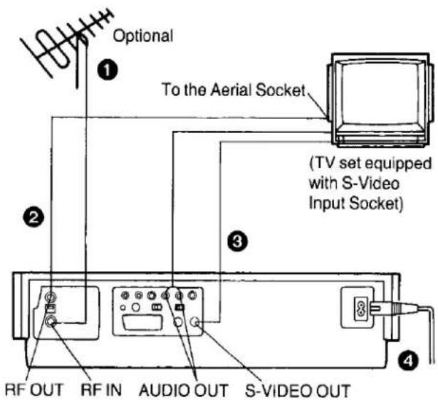
① Connect the external aerial to the RF Input Socket on the VTR.
2 Connect the aerial terminal on your TV set to the RF Output Socket on the VTR with the supplied DIN-DIN Coaxial Cable.
3 Connect the S-Video Output Socket on the VTR with the S-Video Input Socket on the TV set, and the Audio Output Sockets on the VTR with the Audio Input Sockets on the TV set.
4 Connect the AC Mains Lead to the AC Mains Socket of the VTR, and a mains outlet.
Normal/Y/C Selector

NOR: Normally set to this position.
Y/C: Set to this position when connecting the VTR to a TV set equipped with 21-pin AV Connector with pins for separate Y/C signal input.
INSTALLATION
Consult your Panasonic dealer for advice about a suitable cable to use for connection to the AV Socket.
Connection to a TV Set without AV Socket

1 Connect the external aerial to the RF Input Socket on the VTR.
2 Connect the aerial terminal on your TV set to the RF Output Socket on the VTR with the supplied DIN-DIN Coaxial Cable.
3 Connect the AC Mains Lead to the AC Mains Socket of the VTR to the mains outlet.
Note:
Connect the Audio/Video Output Sockets to the Input Sockets on the TV set (if equipped with these Sockets) for watching the TV in AV mode.
Connection to a TV Set with AV Socket

① Connect the external aerial to the RF Input Socket on the VTR.
② Connect the aerial terminal on your TV set to the RF Output Socket on the VTR with the supplied DIN-DIN Coaxial Cable.
③ Connect the AV Socket on the VTR to the AV Socket on the TV set.
●The AV Socket allows recording and playback of picture and sound. This connection can be used with TV sets which are also equipped with a AV Socket.
④ Connect the AC Mains Lead to the AC Mains Socket of the VTR to the mains outlet.
Connection to a Stereo Amplifier

1 Connect the Audio Input Sockets on the VTR to the REC OUT Sockets on the Stereo Amplifier.
2 Connect the Audio Output Sockets on the VTR to the PLAYBACK Sockets on the Stereo Amplifier.
- If a AV cable is used for the VTR to TV connection and both the VTR and TV set have an Input Selector, set only one of them to "AV".
If both are set to "AV", picture and sound distortion may appear with some types of TV sets. - Some TV sets can automatically switch to the "AV" input mode when VTR playback starts via the AV cable. But some TV sets have to be switched manually to the AV mode.
- For recording from a TV's tuner via the AV cable, set the VTR to the AV mode.
TUNING THE TV SET TO THE VIDEO PLAYBACK CHANNEL
The adjustments described on this page are not necessary, if the VTR is connected to the TV set via the Video/Audio output sockets.
Disconnect the AV Cable when adjusting the TV set to the video playback channel by using the test pattern.

RF Signal Level Switch:
Used to attenuate the reception of the UHF aerial signals. If the reception is normal, set to "HIGH". If the signal is strong (stripes appear in the upper part of the picture), set to "LOW".
1 Turn the TV set on and select the AV programme position or another programme position that is not occupied by any TV station.
② Press the VTR On/Off Switch to turn the VTR On.
(FRONT SIDE)

●The corresponding indicator lights up.
3 Set the Comb Filter/Test Signal Switch to "TEST".

4 Tune the selected programme position of the TV set to UHF approx. channel 36. Confirm on your TV set that the received test pattern is as shown.

natural_image
Abstract black and white striped pattern with no text or symbols5 Set the Comb Filter/Test Signal Switch to "Off". Your TV is now ready to receive the RF output signal from the VTR.

Comb Filter/Test Signal Switch
For RF & normal video use, set this switch to the "OFF" position to improve noise in the picture. Set it to "ON" to improve the frequency response.
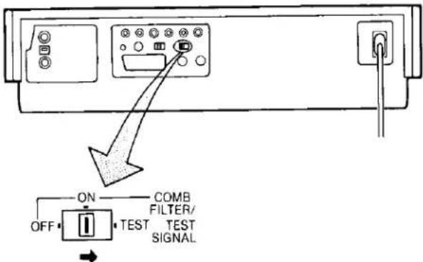
This VTR is equipped with a Comb Filter.
- To achieve higher resolution, the Comb Filter/Test Signal Switch can be set to the "On" position for recording.
Note: When recording via the S-VIDEO Input Socket, this switch does not function.
SETTING THE TUNER IN THE VTR
The tuner in the VTR makes it possible to receive TV broadcasts and to record these programmes without having to turn on the TV set. The frequency band of this model extends from UHF channel 21 to 69.
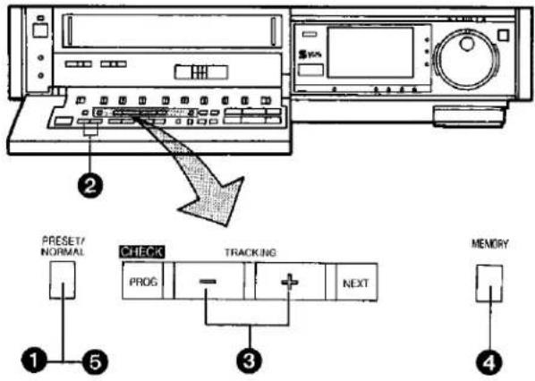
Preparation
●Turn the TV set on and select the programme position (channel) which you have tuned to the video playback channel.
- Press the VTR On/Off Switch to turn the VTR on.
- Set the Input Signal Selector to "Tuner".
① Press the Preset/Normal Button.
The indication on the Multi-Function Display changes from the clock indication to the position indication.
2 Press the Channel Up or Down Button to select a programme position (channel) which you want to tune to a TV station.
Display of the programme positions 1–99


Selection of the programme position
The tuner in the VTR can be preset with up to 99 stations.
③ Press the "+" or "-" Button.

During the station search (The position indication flashes on and off.)
Tuned condition
- When the tuning of the station is completed, the indication stops flashing and the tuned station is automatically memorized.
- At every push of the "+" or "-" Button, the station will be tuned automatically.
4 Press the Memory Button.
(Programme position display flashes once.)
Repeat steps ②—④ for each channel you want to tune to a station.
5 Press the Preset/Normal Button again.
The indication on the Multi-Function Display changes back to the previous indication.
How to Select the Programme Position (Channel) on the Remote Controller
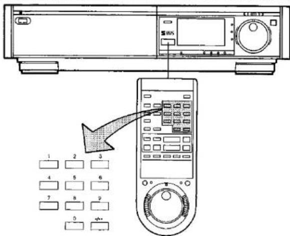

If more than 5 seconds pass between the first, second and third push, the channel will not be changed normally.
Channel Selection with the Remote Controller
The same channel selection as with the Channel Up or Down Buttons on the VTR can also be performed with the Jog Dial on the Remote Controller.

1 Press the Channel Mode Button so that the adjoining Channel Indicator lights up.
② Turn the Jog Dial to select the desired TV station.
●After the desired TV station is selected, press the Channel Mode Button to turn off the Channel Indicator.
SETTING THE CLOCK TO THE PRESENT TIME
The built-in digital clock employs the 24-hour system.

For Example: Set the clock for Sunday, October 10, 1999, 9:10
- Connect the VTR to the mains outlet.
- Press the VTR On/Off Switch to turn the VTR On.
When connecting this VTR to the mains or after a long power failure, the time indications flash.

natural_image
Simple diagram with two rectangular blocks and a dot pattern inside, no text or symbols present.② Press the Clock Button to start the date and time setting.
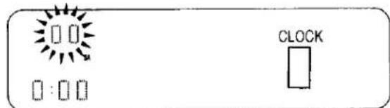
③ Press the "+" or "-" Button to set the year.

4 Press the Next Button.
⑤ Press the "+" or "-" Button to set the month.

6 Press the Next Button.
7 Press the "+" or "-" Button to set the date.

8 Press the Next Button.
9 Press the "+" or "-" Button to set the hour.

10 Press the Next Button.
11 Press the "+" or "-" Button to set the minute.

12 Press the Clock Button when the present time becomes exactly 9:10'00".

At every push of the Next Button, the flashing indication changes in the following order.
YEAR→MONTH→DATE→HOUR→MINUTE
●In case of a power failure, the timer back-up system
maintains the clock operation and timer content for at least 30 seconds. However, depending on the charging time and the memory content, the back-up time may be considerably longer. However, it takes more than 60 minutes for the back-up circuit to become operational, after the VTR is connected to the mains.
- The Timer Record Function should be set to "Off", otherwise the VTR cannot be operated normally. In this case, the Timer Record Indicator "[☐]" will flash to warn you.
- During date setting, the corresponding day is simultaneously set.
●The clock/timer of the VTR is programmed with the calendar up to the end of the year 2087.
The indications 88-99 are for the years 1988-1999.
The indications 00-87 are for the years 2000-2087.
SETTING THE CLOCK TO THE PRESENT TIME (CONT'D)
Setting the Clock to the Present Time Using the Bar Codes

flowchart
graph TD
    A["Start Menu"] --> B["Data Link"]
    B --> C["Security Block"]
    C --> D["Control Panel"]
    D --> E["1"]
    D --> F["2"]
    D --> G["3"]
Preparation
- Set the Digital Scanner On/Off Switch to "ON".
1 Trace the bar code "SETTING OF THE CLOCK".

② Trace the bar code for the year (YEAR).

3 Trace the bar code for the month (MONTH).

4 Trace the bar code for the day of the month (DATE).
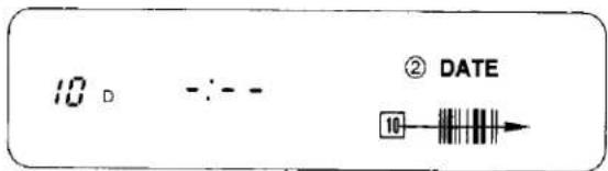
5 Trace the bar code for the hour (START TIME).

6 Trace the bar code for the minute (MIN).

7 Press the Transmit Button on the Digital Scanner and then confirm that the time is displayed in the Multi-Function Display of the VTR.

8 Set the Digital Scanner On/Off Switch to "OFF".
- If the transmission was not received correctly, the "Beep-Beep, Beep-Beep" sound from the VTR will warn you. In this case, perform transmission again.
- If the Digital Scanner is left with no operation performed for more than 4 minutes, it will automatically switch over to the power-saving standby condition and the lamp in the reading tip goes out. (In this case, bar codes that have already been read but not yet transmitted to the VTR) will be cancelled.
●The bar codes "SETTING OF THE CLOCK", "YEAR" and "MONTH" are located on page 3 of the Programming Sheet.
THE VIDEO CASSETTE
Inserting a Video Cassette (Auto Operation)
① Press the Control Panel Open Button.

② Insert the video cassette as shown. The VTR will be turned on automatically and the cassette will be automatically drawn into the VTR.


③ When a video cassette is inserted, the "oo" mark will appear.
Notes:
- When a video cassette with broken out erasure prevention tab (for example a pre-recorded tape) is inserted, playback will start immediately.
- Use VHS and SVHS video cassette tapes only.
Removing a Video Cassette
4 Press the Eject Button (▲).

Simply press the Eject Button; the VTR turns itself on, ejects the cassette and turns itself off again.

To prevent accidental erasure

To record again

Auto Operation
Auto VTR On
When a cassette is inserted, the VTR turns itself on automatically.
Auto Play
If the tab of the inserted cassette is broken out, playback will start automatically without having to press any button.
Auto Rewind
When the tape reaches its end during recording (except OTR and timer recording) or playback, it will automatically be rewound to the beginning.
Auto Eject
When trying to record on a cassette whose tab is broken out, the cassette will automatically be ejected to warn that the recording cannot be made.
VTR-Off Eject
When the VTR is off, the inserted cassette can be ejected simply by pressing the Eject Button, and the VTR will automatically turn itself off again.
Rewind Auto Shut Off
When the VTR On/OFF Button is pressed during rewinding, the cassette will be ejected as soon as the beginning of the tape is reached, and the VTR will turn itself off.
Auto Timer Recording Standby
When the Timer Record Button is pressed during redding, the VTR will switch over to the timer recording standby mode after the beginning of the tape is reached.
PLAYBACK
Preparation
● Make sure that the Timer Record Function is set to "Off".
- insert a recorded video cassette.
When a video cassette is already inside the VTR, press the VTR On/Off Switch to turn it on.
● Turn the TV set on and select the video playback channel.
- Set the Noise Filter/Edit Selector to "Off".
- Set the Digital Tracking Switch to "On".
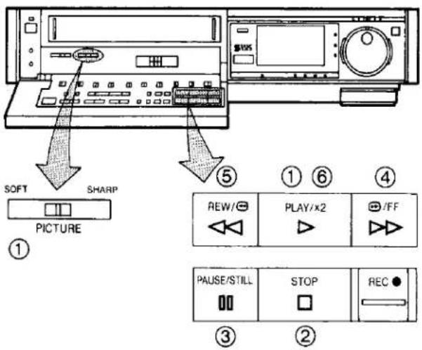
1 Normal Playback
Press the Play/×2 Button (▶).

●Control the picture as you like with the Picture Sharpness Control (sharp or soft contours).
The format that was used for recording of the tape (VHS or S-VHS) is automatically detected and selected for playback.
② To Finish Playback
Press the Stop Button (■) to stop the playback.
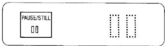
③ Super Still Playback
When the VTR is in the playback mode, press the Pause/Still Button (■) to view a still-picture. To continue the normal playback, press this button again.
4 Cue Playback
When the Fast Forward ▶▶/Cue ▶▶ Button is kept pressed while the VTR is in the playback mode, the tape will be played back at high speed in forward direction.

5 Review Playback
When the Rewind ◀◀/Review ◀◀ Button is kept pressed while the VTR is in the playback mode, the tape will be played back at high speed in reverse direction.

To make possible Cue or Review playback without having to keep the respective button pressed, first press the Memory/Repeat/Search Button on the Remote Controller so that the Search Indicator "S" appears in the Multi-Function Display, and then press the Fast Forward ▶▶/Cue ▶▶Button or the Rewind ◀◀/Review ▶◀Button. To switch the VTR back to normal playback, press the Play/×2 Button (▶).
- When Cue or Review playback continues for more than 10 minutes, the VTR will automatically switch back to the normal playback mode.
6 Double Speed Playback
When the VTR is in the playback mode, press the Play/×2 Button (▶) to view the action at twice the normal playback speed. To change back to normal playback, press the Play/×2 Button (▶) again.

Using the Remote Controller


Super Still Advance Playback
Press the Still Advance Button (Ⅱ) while the VTR is in the still playback mode. Each time you press this button, the still-picture will advance one single field.


●The sound will be played back only during normal playback.
- If you leave the VTR in the still and slow playback mode for more than 5 minutes, the VTR will automatically switch over to the Stop mode to protect the tape and the video heads.
- Noise which takes the form of horizontal bars appears on the TV in the Cue and Review playback modes. This is not an indication of a malfunction.
●The top of the picture may become distorted in the Cue, Review or Super Still (LP) mode. This is not an indication of a malfunction.
- When the picture rolls vertically in the Cue or Review mode, adjust the vertical hold control on the TV set.
- Immediately after starting Cue or Review playback, the picture may be distorted. Also, when these modes are cancelled, some momentary picture distortion may occur. However, this is not due to any malfunction.
- In "LP" mode only:
-
During any playback mode other than normal playback, the picture may have some noise bars, the colour may be unstable, or a black and white picture may appear.
-
When playing back a tape which was recorded on another VTR, it may be necessary to adjust the Tracking Control. In some cases the picture quality may still be inferior. This is due to limitation of format.
PLAYBACK (CONT'D)
Using the Shuttle Ring
With the handy Shuttle Ring, the playback speed can be adjusted step by step in both forward and reverse directions.

When the VTR is in the stop or playback mode, press the Jog/Shuttle Button (the playback will start at the speed that corresponds with the setting of the Shuttle Ring).
② Turn the Shuttle Ring to select the desired playback speed and direction.
Shuttle Ring Setting and Corresponding Playback Speed and Direction

flowchart
graph TD
    A["1"] --> B["2"]
    B --> C["3"]
    C --> D["4"]
    D --> E["5"]
    E --> F["6"]
    F --> G["7"]
    G --> H["8"]
    H --> I["9"]
    I --> J["REV"]
    I --> K["FWD"]
    style A fill:#f9f,stroke:#333
    style B fill:#f9f,stroke:#333
    style C fill:#f9f,stroke:#333
    style D fill:#f9f,stroke:#333
    style E fill:#f9f,stroke:#333
    style F fill:#f9f,stroke:#333
    style G fill:#f9f,stroke:#333
    style H fill:#f9f,stroke:#333
    style I fill:#f9f,stroke:#333
    style J fill:#f9f,stroke:#333
    subgraph Directional Path
        direction LR
        L1["Reverse Direction"] --> L2["Forward Direction"]
    end
| Playback Mode | Indication |
| 1 Review Playback | |
| 2 Double Speed Reverse Playback | |
| 3 Reverse Playback | |
| 4 Reverse Slow Motion Playback | |
| 5 Still Playback | |
| 6 Slow Motion Playback | |
| 7 Normal Playback | |
| 8 Double Speed Playback | |
| 9 Cue Playback |
Note:
By tuning the shuttle ring, a desired Playback mode can be selected while observing the Playback mode indicator on the Multi-Function display.
●The Figures on the Shuttle Ring Scale Indicate Multiples and Fractions of the Normal Playback Speed.
The Cue and Review playback speed will be different for recordings made in the SP and LP mode. The figures in parenthesis ( ) indicate the speed for recordings made in the LP mode.
- If Cue or Review playback continues for more than 10 minutes, the VTR will automatically switch over to the normal playback mode. If the Still and Slow playback continues for more than 5 minutes, the VTR will automatically switch over to the stop mode.
- To return to normal playback, press the Play/×2 Button (▶) or the Jog/Shuttle Button.
The following may happen except during Slow and Normal playback in forward direction.

● Horizontal noise bars may appear in the picture, as shown above, or the top of the picture may become distorted.
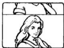
- When the picture rolls vertically, adjust the vertical hold control on the TV set.
Still and Slow Playback
- Depending on the TV set used, it may not be possible to obtain a proper picture during Still and Slow playback.
- If the TV set is equipped with an automatic vertical hold control, the picture may shake vertically. In this case, set the TV set's vertical hold (AUTO/MANUAL) selector to the "MANUAL" position, and adjust its vertical hold control.
- When changing over from Review Search to Still play-back, the picture will reverse by a few frams approx. 2 seconds later.
Using the Jog Dial
The convenient Jog Dial makes it easy to locate any desired frame with utmost precision.

① Press the Jog/Shuttle Button while the VTR is in the stop mode or in the playback mode.
② Return the Shuttle Ring to the center "click" position (Still playback mode).
3 Turn the Jog Dial clockwise or counterclockwise.
●The field advance speed changes according to the speed with which the dial is turned.
- To return to normal playback, press the Play/×2 Button (▶) or the Jog/Shuttle Button.
Turning the Jog Dial
- Every turn of approx. 30° will advance or reverse the tape by one field.
● A turning speed of the Jog Dial of more than 3 rotations per second corresponds to the normal playback speed.
Slow Tracking Control
- When noise bars appear during Super Still, Super Still Advance or Super Fine Slow playback, switch over to Slow playback and adjust with the Tracking (+) or (−) Button to reduce the noise bars.
- It may not be possible to eliminate the noise bars completely.
Operating the Shuttle Function with the Shuttle Ring on the Remote Controller

- The operation is the same as steps ① and ② described on page 20.
With the Shuttle Ring, the following playback functions can be selected: Normal playback in forward and reverse direction, Still playback, Cue & Review playback at 5 times (5) and 9 times (19) normal speed as well Slow motion playback in forward and reverse direction at 1/3th of normal speed.
(The figures in parentheses indicate the speed for recordings in the LP mode.)
Operating the Jog Function with the Jog Dial on the Remote Controller

The operation is the same as the operation steps ① to ③ on this page.
- To return to normal playback, press the Play/×2 Button.
- To be able to use the Jog or Shuttle function when the Jog/Shuttle Indicator is not lit, simply press the Jog Shuttle Button again.
● After finishing with the Jog or Shuttle function, press the Jog/Shuttle Button to turn off the Jog/Shuttle Indicator. - Although the Jog/Shuttle Indicator on the VTR may light up during operation with the Remote Controller, all operations should be made via the Remote Controller.
PLAYBACK (CONT'D)
Repeat Playback

Repeat Playback between the Beginning of the Tape and the End of the Recorded Part
To play back the tape repeatedly between the beginning of the tape and a place where the video signal is interrupted for at least 5 seconds (see diagram below).
① Press the Memory/Repeat/Search Button so that the Repeat Indicator "R" lights up.

② Press the Play/×2 Button (▶).
- The playback will continue until the VTR detects the end of the video recording (no control signal for more than 5 seconds). At this point, the tape will be re-wound to the beginning and the playback will be repeated.

Control signal Interruption (at least 5 sec.)
- If the interruption of the control signal is less than 5 seconds, the playback will continue (no rewind from this point and repeat).
3 To stop the Repeat playback, press either the Stop Button or the Memory/Repeat/Search Button (the Repeat Indicator "R" will go out).
Note:
- If a short tape portion is played back many times, the tape may become damaged at that part.
Rewind and Fast Forward
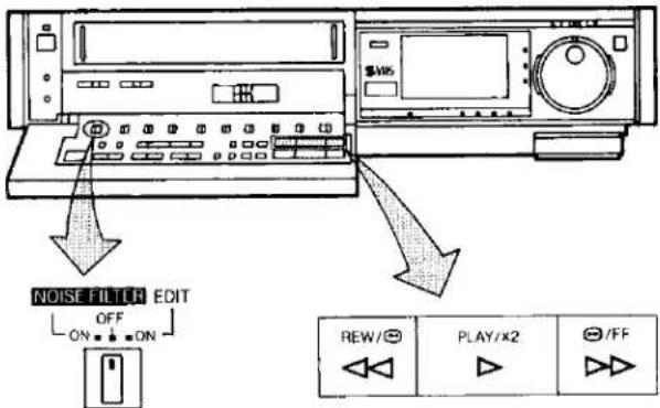
Press the Rewind ◀◀/Review 📋 Button to rewind the tape.

Press the Fast Forward ▶▶/Cue ▶▶ Button to wind the tape forward rapidly.

Lap Time Counter
It shows the elapsed recording or playback time.
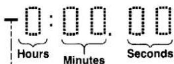
The “-” indication will appear when the tape is rewound further than the tape counter position "0:00.00".
- If the figures on the Tape Counter do not change during Fast Forward, Rewind or any of the Playback functions, this means that nothing is recorded on that tape section.
●The Tape Counter is automatically reset to "0:00.00" when the video cassette is inserted.
Auto Cue and Play
When inserting a video cassette which has the erasure prevention tab removed playback will start automatically. If nothing is recorded on the part of the tape where playback is started, the VTR will automatically be in the Cue playback mode until the recorded part is reached, then it changes back to normal playback mode.
This applies only to previously unused tapes. Tapes which have been erased or re-recorded will not exhibit this feature.
Noise Filter/Edit Selector
EDIT ON: For editing operations such as dubbing.
OFF: For ordinary use of the VTR.
NOISE FILTER ON: For playback of tapes with inferior picture quality caused, for example, by repeated dubbing.
- When the Noise Filter/Edit Selector is set to "EDIT ON", the picture sharpness cannot be adjusted with the Picture Sharpness Control.
- When playing back S-VHS recordings, the "NOISE FILTER ON" position will have no effect.
PLAYBACK (CONT'D)

Counter/Remaining Tape Time Selector Button
When the VTR is turned on, this button can be pressed to change the display mode of the Multi-Function Display between "COUNT" (Tape Counter) and "REMAIN" (Remaining Tape Time).
Indication of the Remaining Tape Time
When the Counter/Remaining Tape Time Selector Button on the VTR (or the Tape Remain Button on the Remote Controller) is pressed, the approximate remaining tape time will be displayed in hours and minutes.
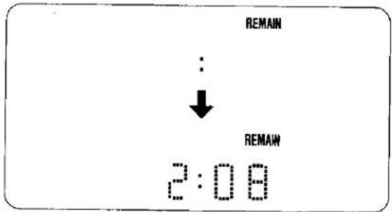
●The Remaining Tape Time Indication will remain displayed even after the tape is ejected. However, when next inserting a cassette, this indication will be cancelled.
● This functions lets you know the remaining tape time even during Rewind and Fast Forward Operations.
- If this button is pressed while the VTR is in the stop mode, playback will start automatically and continue until the remaining tape time has been calculated and is displayed, and the VTR will then switch over to the stop mode again.
- When using a VHS-C videocassette in this VTR, the remaining tape time indication may not be correct or this indication may not appear at all.
Tape Select Switch
To obtain a correct Remaining Tape Time indication when using an NV-E240 video cassette tape, this switch must be set to the "E240" position.
When using NV-E30, 60, 90, 120, 180 or 195 video cassette tapes, set this switch to the “\~E180” position.
If cassettes with other tape lengths than the above are used, the Remaining Tape Time indication will not be precise.
Digital Tracking Selector
Digital Tracking
ON: Select this position for digital tracking.
When playback is started after inserting a cassette, and the VTR is turned on, the Digital Tracking function will be activated automatically, the Digital Tracking Indicator will flash for several seconds, and the tracking will be adjusted automatically (after the adjustment, the Digital Tracking Indicator will remain lit).
- When the Digital Tracking Indicator is lit and the tape speed (SP/LP) is changed, the Digital Tracking function will be activated. However, when operating any function other than playback, insert editing and audio dubbing, this function will not work.
●During playback, the Digital Tracking function will be activated whenever the playback changes over from an unrecorded part to a recorded part, provided the recorded part is longer than 4 seconds.
- When the picture is distorted by noise bars, press the Tracking (+) or (−) Button to select manual tracking and adjust with these two buttons. The Digital Tracking Indicator goes out.
To change back to Digital Tracking, press the Tracking (+) and (−) Buttons simultaneously.
●The Digital Tracking function works only in the normal playback mode.
Manual Tracking
OFF: Select this position for manual tracking.
- When the playback picture is distorted by noise bars, adjust by pressing the Tracking (+) or (−) Button.
- To return the Tracking Control to the former setting, press the Tracking (+) and (−) Buttons simultaneously.
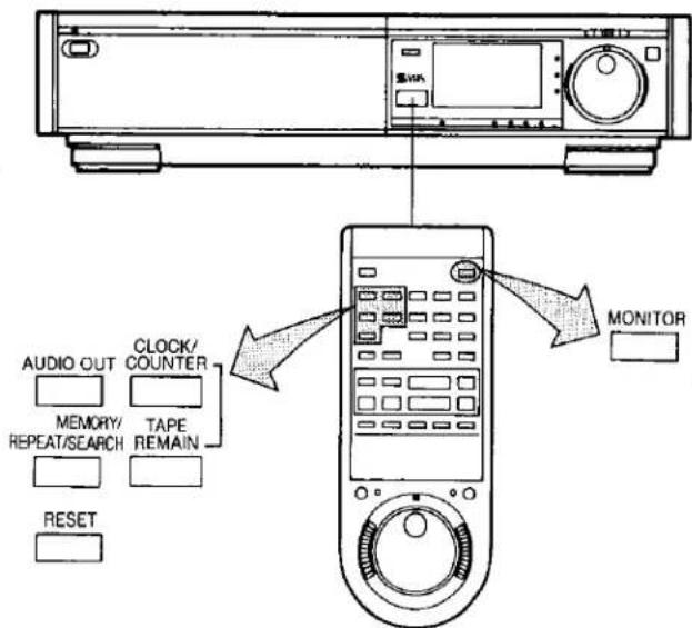
Memory/Repeat/Search Button
Repeatedly pressing this button will change the indication in the following order: "M" (Memory)→"R" (Repeat)→"S" (Search)→"RS" (INDEX Repeat)→ all indications are off→"M"...
Clock/Counter Selector
By pressing this button when the VTR On/ Off Switch is set to "On", it is possible to change over the display mode of the Clock/Counter Display in the Multi-Function Display from "Clock" to "Counter" Display and vice versa.
- Even if the selector button is set for "Counter" the display will automatically changes over to "Clock" Display in all the following cases; When you set the VTR On/Off Switch to "Off", adjust the clock to present time, programme a timer recording, check a timer recording programme or programme and perform an OTR.
- When the Clock/Counter Display shows the time, the counter cannot be reset and the Memory and Search Function cannot be activated ("M", "R" and "S" indication does not light up).
Memory Function
The Memory function makes it simple and fast to find a certain position on the tape later again, simply by pressing the Reset Button at that position to set the tape counter to "0:00.00" and by pressing the Memory/Repeat/Search Button. During Rewind or Fast Forward, the tape will then stop at approximately the desired position.
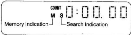
- Even if the Clock/Counter Display is switched over to "Clock" Display after pressing the Memory/Repeat/Search Button, the Memory function will stop the tape at the desired position.
Search Lock Indication
Press the Memory/Repeat/Search Button repeatedly until "S" (Search) lights up. With the VTR in the playback mode, it is now possible to perform fast picture search for about 10 minutes in forward or reverse direction. The corresponding button (Cue or Review) does not need to be kept pressed in this function.
Monitoring Function
When the Monitor Button is kept pressed during Playback or Still playback, the broadcast picture of the selected programme position (channel) or input signal through Audio/Video input socket will be displayed. When this button is released, the picture will change back to the playback picture of the tape.
- When the VTR is connected to the TV set via AV Cable, this function does not work.
RECORDING FROM A TV BROADCAST SIGNAL

| REW/∅ | PLAY/x2 | ∅/FF |

Preparation
● Make sure that the Timer Record Function is set to "Off".
- Reset the Tape Counter to "0:00.00".
- Insert a video cassette with the erasure prevention tab intact.
When a video cassette is already inside the VTR, press the VTR On/Off Switch to turn it on.
- Set the Input Signal Selector to "Tuner".
- Set the Tape Speed Selector to "SP" or "LP".
- Set the Audio Rec Level Control Selector to "AGC".
1 Select on the VTR, the programme position (channel) to be recorded. In order to confirm proper reception, turn on the TV set and select the video playback channel.
② Set the S-VHS Selector to "ON".
ON: S-VHS cassette tape are automatically recorded in the S-VHS format and VHS cassette tapes are automatically recorded in the VHS format.
OFF: To make a recording in the VHS format on an S-VHS cassette tape.
③ Press the Record Button (●).
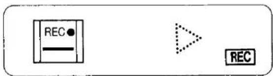
When a video cassette with broken out tab is inserted, it will be ejected automatically.
● During recording, the programme position (channel) on the VTR cannot be changed.
- To start a recording with the Remote Controller, press the two Record Buttons on the Remote Controller simultaneously.
To Finish the Recording
4 Press the Stop Button (■).
If You Wish to Avoid Recording Unwanted Material
5 Press the Pause/Still Button (11) to stop the tape temporarily.
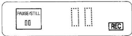
- Press the Pause/Still Button (Ⅱ) again to continue the recording.
- If you leave the VTR in the pause mode for more than 5 minutes, the VTR will automatically switch over to the stop mode to protect the tape and the video heads.
Recording One TV Programme While Watching Another
- Record (following steps ① to ③).
- Select the desired programme position (channel) on your TV set.

Tape Speed Selector (SP/LP)
For recording, either of two tape speeds can be selected. During playback, the VTR will automatically select the correct speed.
- SP Mode: For better picture quality.
●LP Mode: For longer recording time.
It is not recommended to change from the SP to the LP mode or vice versa in the middle of recording. Even if the switching is done while the VTR is in the pause mode, picture distortion will occur at the switching point during playback.
Note:
The picture quality in the LP mode is not as good as that in the SP mode.
Manual Adjustment of the Audio Recording Level
Manual adjustment of the Audio recording level may be desirable when using the VTR as a hi-fi audio recorder or when producing your own video tapes.
- Set the Audio Rec Level Control Selector to "Manual" and adjust the recording volume with the Hi-Fi Rec Level Controls while observing the Audio Level Meters. The recording level for the right and left channel can be adjusted individually.
(It is recommended to adjust so that peaks in the audio level reach about 5 dB.)
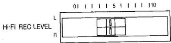
- For all Timer Recordings and also for normal recordings of TV programmes, the Audio Rec Level Control Selector is usually set to "AGC" for automatic adjustment of the audio recording level.
- Manual adjustment of the audio recording level is only possible for the sound which is to be recorded on the hi-fi audio tracks. The sound to be recorded on the "Normal" audio track will be adjusted automatically.
NICAM SYSTEM
The NICAM system is a ground-based TV service for digital stereo sound. To receive NICAM broadcasts, the NV-FS100 incorporates a NICAM decoder.
When a stereo, dual-soundtrack or monaural NICAM programme is being received, the indicators light up to inform you of the type of broadcasts. The NICAM programmes are always accompanied by standard broadcasts and you can select the desired soundtrack for recording with a single switch. NICAM soundtracks can only be recorded on the hi-fi audio track.

Preparation
- Set the Input Signal Selector to "Tuner".
Recording of a NICAM stereo programme
STEREO

The STEREO Indicator is lit while a NICAM stereo programme is being received. To record such a programme, set the Nicam/Mono Switch to "NICAM".
NICAM stereo sound will be recorded on the hi-fi track and the regular (standard) sound will be recorded on the normal audio track.
Recording of a NICAM dual-sound track programme
STEREO

Both the M1 and M2 Indicators are lit while a NICAM dual-soundtrack programme is being received. To record such a programme, set the Nicam/Mono Switch to "NICAM".
The M1 and M2 sounds will be recorded on the hi-fi track: M1 on the left channel and M2 on the right channel.
Recording of a NICAM monaural programme
STEREO

Only the M1 Indicator is lit while a NICAM monaural programme is being received. To record such a programme, set the Nicam/Mono Switch to "NICAM". The same monaural sound will be recorded on both channels of the hi-fi track.
Recording options according to the type of broadcasts and the setting of the Nicam/Mono Switch
| Type of broadcast\Nicam/Mono switch position\Audio track | Normal audio track (mono) | Hi-fi audio track | ||
| L | R | |||
| Regular broadcast (standard audio) | Either position | Standard audio | Standard audio | Standard audio |
| Regular+NICAM stereo (L, R) | NICAM | Standard audio | Stereo L | Stereo R |
| MONO | Standard audio | Standard audio | Standard audio | |
| Regular+NICAM dual mono (M1, M2) | NICAM | Standard audio | M1 | M2 |
| MONO | Standard audio | Standard audio | Standard audio | |
| Regular+NICAM mono | NICAM | Standard audio | M1 | M1 |
| MONO | Standard audio | Standard audio | Standard audio | |
Note: NICAM audio programmes cannot be recorded on the normal audio track.
NICAM SYSTEM (CONT'D)
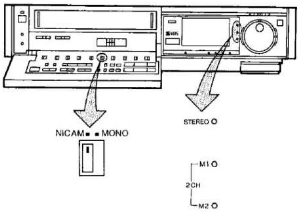
Nicam/Mono Switch
- When a NICAM programme is being received, this switch can be used to select the desired type of sound to be recorded on the hi-fi audio track. This switch functions only when the Input Signal Selector is set to "TUNER". To record a NICAM programme, this switch must be set to "NICAM".
Note:
If NICAM broadcast signals are weak, the sound quality deteriorates remarkably. When the signals are extremely weak, the Audio Recording Mode Indicator ( ^M1 ^M2 STEREO) goes off and the FM sound is recorded on the hi-fi track irrespective of the setting of this switch.
- If the Nicam/Mono Switch is intentionally set to "MONO" even through a NICAM programme is being received, the indicator(s) remain lit.
- To record the regular sound (ordinary normal sound) on the FM audio tracks when a NICAM programme is received, set the Nicam/Mono Switch to "MONO".
- When a NICAM programme is received and the sound is distorted due to inferior reception conditions, set the Nicam/Mono Switch to "MONO".
HI-FI AUDIO SYSTEM

Recording of Simulcast Sound
Preparation
- Connect your VTR to the Stereo Amplifier and FM Stereo Tuner as described on page 30.
● Tune the FM Stereo Tuner to the desired station. - Set the Input Signal Selector to "Tuner".
① Set the Simulcast Switch to "On" position.
- The operation procedure is the same as for normal recording; see "Recording from a TV broadcast signal" on page 26.
While this switch is in the "On" position, the sound portion of the TV broadcast signal will be recorded only on the "normal" sound track. And the stereo sound signal received via the FM tuner will be recorded on the hi-fi sound tracks.
Playback (or Monitoring during Recording)
Press the Audio Output Mode Selector on the Remote Controller to select the desired sound mode.
At the every push of this button, the audio output mode changes as follows:

and the Left and Right Indicators show which sound mode is selected in the following way.
Stereo: Both the Left and Right Indicators are lit.
Left: The Left Indicator is lit.
Right: The Right Indicator is lit.
Normal: Both the Left and Right Indicators are not lit.
●The Audio Rec Level Control Selector must be set to "AGC", if no manual adjustment is to be carried out.
- If a video cassette recorded on this VTR with stereo or bilingual sound is played back on a conventional VHS video recorder, the sound will be reproduced from the normal audio track (in mono).
SUPER OTR FUNCTION (ONE-TOUCH TIMER RECORDING)
This convenient function makes it possible to easily programme the VTR for recording of TV programmes with immediate start or with start within 24 hours by precisely setting the starting time and ending time to the desired minute, and the VTR will automatically turn itself off when the recording ends.

Preparation
●Make sure that the clock shows the present time correctly.
- Insert a video cassette with the erasure prevention tab intact.
When a video cassette is already inside the VTR, press the VTR On/Off Switch to turn it on.
- Set the Input Signal Selector to "Tuner".
- Set the Tape Speed Selector to "SP" or "LP"
- Set the Audio Rec Level Control Selector to "AGC".
It is possible to programme an OTR recording for a TV programme which will start immediately or within the next 24 hours.
(For example, OTR recording of a TV programme broadcast from 10:30 to 11:00.)
1 Select the programme position (channel) to be recorded.
2 Press the OTR On (+) or (−) Button to set the OTR starting time to 10:30.
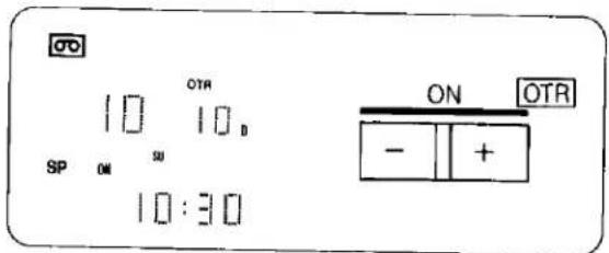
●The "OTR" indicator will be displayed.
When a video cassette with broken out tab is inserted, it will be ejected automatically.
3 Press the OTR Off (+) or (−) Button to set the OTR ending time to 11:00.

- When quickly and repeatedly pressing the OTR On (+) or (−) Button or the OTR Off (+) or (−) Button, the corresponding time indication changes in 1-minute steps. When it is kept pressed, the indication changes in 10-minute steps.
- After setting the OTR starting time in step 2, the OTR Off (+) or (−) Button must be pressed within 8 seconds to select the OTR ending time, otherwise the selected starting time will be cancelled.
After 4 seconds, the display will automatically change back to the starting time indication.

To confirm the OTR ending time, press the Check/Programme Button once. When this button is pressed twice, the display will change to the clock indication mode.

- The VTR will automatically switch off, when the OTR is completed. To turn the VTR on again, press the VTR On/Off Switch.
SUPER OTR FUNCTION (ONE-TOUCH TIMER RECORDING) (CONT'D)

OTR Function with Immediate Start
1 Select the programme position (channel) to be recorded.
2 Press the OTR Off (+) or (−) Button to set the OTR ending time to 11:00.

- When the tab of the inserted video cassette is broken out, it will be ejected automatically.
●The "OTR" indicator will be displayed.
- The VTR will automatically switch off, when the OTR is completed. To turn the VTR on again, press the VTR On/Off Switch.
When the Check/Programme Button is pressed once, the present time will be displayed.
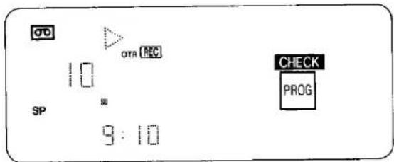
When the Clock/Counter Selector Button on the Remote Controller is pressed during OTR recording, the display will change over to the counter mode.

- When the tape reaches its end during an OTR the VTR will turn itself off.
- Make sure that the OTR Function (One-Touch Timer Recording) does not overlap a programmed timer recording. An OTR always takes precedence over a timer recording.
- It is possible to change the OTR starting time or the ending time before the recording starts.
- It is possible to perform any VTR operation (except timer recording) until the recording starts.
- It is possible to change the OTR ending time even during the recording.
● To interrupt an OTR, press the VTR On/Off Switch to turn the VTR off.
TIMER RECORDING
The programming of timer recordings is possible both on the VTR itself and via the Digital Scanner. Programming of as many as 8 timer recording is possible up to one month in advance.

Preparation
●Make sure that the clock shows the present time correctly.
- Make sure that the Timer Record Function is set to "Off".
- Set the Input Signal Selector to "Tuner"
- Insert a video cassette with the erasure prevention tab intact.
When a video cassette is already inside the VTR, press the VTR On/Off Switch to turn it on.
- Set the Audio Rec Level Control Selector to "AGC".
- Set the Tape Speed Selector to "SP" or "LP".
For Example:
Programming a timer recording for a TV programme that will be broadcast on Wednesday, October 27, from 10:30 to 11:45, on programme position (channel) 12, on timer programme number 2. (Present date=October 10, 1999)
1 Press the Check/Programme Button to select the next unoccupied timer programme number.

2 Press the (+) or (−) Button to select the programme position (channel) on which the TV programme will be broadcast.

③ Press the Next Button.
4 Press the (+) or (−) Button to set the date.
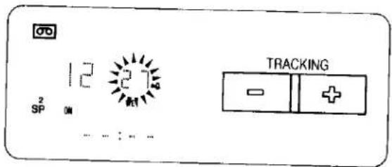
5 Press the Next Button.
6 Press the (+) or (−) Button to select the hour of the starting time of the TV programme.
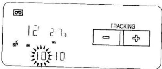
7 Press the Next Button.
8 Press the (+) or (−) Button to select the minute of the starting time of the TV programme.

9 Press the Next Button.
TIMER RECORDING (CONT'D)
10 Press the (+) or (−) Button to select the hour of the end time of the TV programme.

⑪ Press the Next Button.
12 Press the (+) or (−) Button to select the minute of the end time of the TV programme.
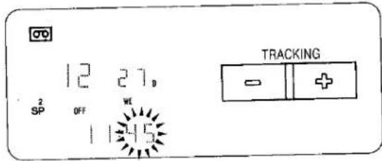
13 Press the Timer Record Button.

For Everyweek Recording
For Example:
Programming a timer recording for a TV programme that is broadcast every week on Sunday, from 10:30 to 11:45 on timer programme number 7.
Programming for everyweek recording can be made on any of the timer programme numbers 1–8.
Execute the operation steps ① to ③.
4 Press the (−) Button repeatedly until the "SU" Indicator (= Sunday) is lit.
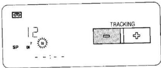
Perform the operation steps 5 to 13.
For Everyday Recording
For Everyday Recording, you have the choice between 3 different modes: Monday through Friday, Monday through Saturday, and Sunday through Saturday.
MO TU WE TH FR ①
MO TU WE TH FR SA ——②
SU MO TU WE TH FR SA—③
For example:
Programme time for timer recording every day from 10:30 to 11:45 on timer programme number 8.
Programming for everyday recording can be made on any of the timer programme numbers 1–8.
Execute the operation steps ① to ③.
4 Press the (−) Button until the desired type of Everyday Recording (①, ②, ③) is displayed.
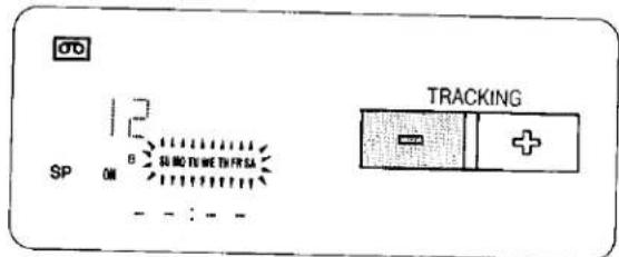
Perform the operation steps 5 to 13.
To Confirm the Programme of a Timer Recording
Make sure that the VTR is turned on.
Make sure that the Timer Record Function is set to "On". Select the programme number to be checked, by repeatedly pressing the Check/Programme Button.
The preset channel and start and ending times of the timer recording will be indicated for about 12 seconds.
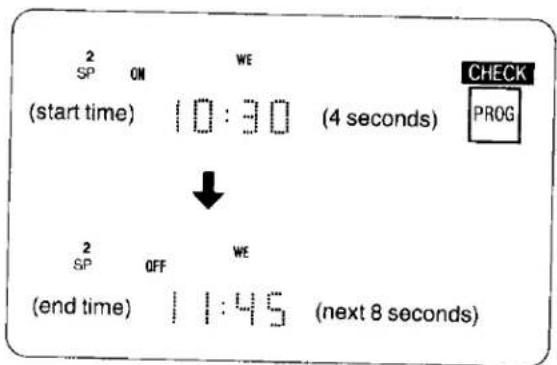
To Cancel a Timer Recording
Make sure that:
the VTR is turned on,
the Timer Record Function is set to "Off".
1 Press the Check/Programme Button repeatedly, until the number of the timer programme that you want to cancel is displayed.
② Press the (+) and (−) Buttons simultaneously for more than 3 seconds.
- After the programmed timer recording has been made, set the Timer Record Function to "Off", otherwise the VTR cannot be operated normally.
● During recording, the programme position (channel) on the VTR cannot be changed. - When you want to watch TV after setting a timer recording, select the desired channel on the TV set.
- To cancel a timer recording during recording, set the Timer Record Function to "Off".
- It is impossible to confirm programmes of timer recordings while an OTR is being performed.
- To turn the VTR on and use it for playback or recording before the timer recording is performed, set the Timer Record Function to "Off".
- When the Timer Record Function is set to "On" but no video cassette is inserted or no timer recording has been programmed, the Timer Recording Indicator will flash to inform that the timer recording cannot be performed.
- If no cassette is inserted in the VTR, the "CO" Mark will flash.
- modified keyboard available if function does not display channel
TIMER RECORDING (CONT'D)

flowchart
graph TD
    A["1 PROGRAMME"] --> B["2 DATE"]
    B --> C["3 START TIME"]
    C --> D["4 END TIME"]
    D --> E["MIN"]
    E --> F["6 50"]
TIMER RECORDING BY USING THE DIGITAL SCANNER
Tracing the Bar Codes
Example: When programming a timer recording for a programme that will be broadcast on channel position 4 on the 3rd of the month, from 7:02 to 7:30, trace the bar codes in the order of the numbered arrows shown below.
- Set the Digital Scanner On/Off Switch to "ON".
① Trace the bar code for "PROGRAMME".

② Trace the bar code for "DATE".
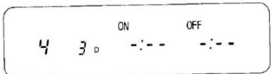
③ Trace the bar code for "START TIME".

4 Trace the bar code for "MIN".

⑤ Trace the bar code for "END TIME".

⑥ Trace the bar code for "MIN".

- The "Bee Bee Bee Bee Beeeeep" sound signals that the scanner is now ready for data transmission.
- When no sound is heard, read the bar codes once again.
- If more than one bar code is read in the same group, only the last code will be effective.
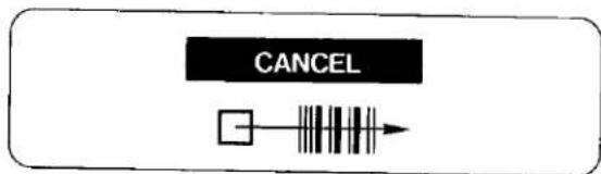
- If the "CANCEL" bar code is read, all bar codes that have been read so far will be cancelled.
Transmit the Programming Data
Keep pressing the Transmit Button and confirm that the programmed data on the Multi-Function Display of the VTR are as desired.
After releasing the button, the data will continue to be displayed for about 12 seconds.

- If the transmission was not received correctly, the "Beep-Beep, Beep-Beep" sound from the VTR will warn you. In this case, perform transmission again.
- The transmission is possible when the VTR is turned on but is not in any of the recording or playback operation modes. It is also possible when the VTR is in the timer recording standby mode (☐ indication is lit).
- The programming will be done on the next lower unoccupied timer programme number (8–1).
- If all programme numbers are occupied, the "Beep-Beep, Beep-Beep" sound from the VTR will warn you that the programming cannot be made.
- When the Transmit Button is pressed, the VTR will automatically be put into the timer recording standby condition and the VTR will be turned off.
- To operate the VTR before the timer recording will be performed, press the Timer Rec. Button to suspend the timer recording standby condition. After using the VTR, be sure to press the Timer Rec. Button again, otherwise the timer recording will not be made.
TIMER ON/OFF
After programming a timer recording, the VTR is in the timer recording standby mode and cannot be used for any other operation, such as playback. If some other operation is desired, first trace the "TIMER ON/OFF" bar code and transmit it to the VTR with the Transmit Button.
To later reset the VTR to the timer recording standby mode, trace the "TIMER ON/OFF" bar code again and transmit it with the Transmit Button.

For Programming More Than One Timer Recording in Succession
Repeat the following operation steps ①-③.
1 Trace the "CANCEL" bar code on the Programming Sheet.
② Trace the bar codes for "PROGRAMME", "DATE", "START TIME" and "END TIME".
3 Confirm that the present time is displayed on the Multi-Function Display of the VTR, and transmit the data.
- If the next timer programming data are transmitted while the previous timer programming data are still being displayed, the displayed timer recording data will be cancelled.
TIMER RECORDING (CONT'D)
For Everyday Recording
When programming an everyday recording using the bar codes, you have the choice between 3 different modes: Sunday through Saturday, Monday through Friday, and Monday through Saturday.

① Turn on the Digital Scanner and trace the "PROGRAMME" bar code.
② Trace the desired "EVERYDAY" bar code (1, 2, 3).
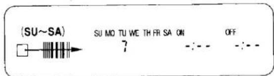
③ Trace the "START TIME" and then the "END TIME" bar codes, and transmit the data to the VTR.
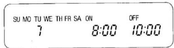
● Everyday recording will be performed from that day on.
- If a "DATE" bar code is traced after tracing the "EVERYDAY" bar code, everyday recording will not be performed.
For Everyweek Recording
① Turn on the Digital Scanner and trace the "PROGRAMME" bar code.
② Trace the bar code for the desired day of the week among the "EVERYWEEK" bar codes.

③ Trace the "START TIME" and then the "END TIME" bar codes, and transmit the data to the VTR.

- Everyweek recording will be performed from that week on. - If a "DATE" bar code is traced after tracing the "EVERY-WEEK" bar code, everyweek recording will not be performed.
To Confirm the Programme of a Timer Recording
To perform this operation, the VTR must be turned on or it must be in the timer recording standby mode (☐ indication is lit).
① Trace the "CHECK" bar code.

② Perform transmission.
●After releasing the Transmit Button, the programmed data will be displayed for about 12 seconds on the Multi Function Display.
- At every push of the Transmit Button, the timer programme number advances to the next higher number.
To Cancel a Programmed Timer Recording
To perform this operation, the VTR must be turned on but not be in any of the recording or playback operation modes, or it must be in the timer recording standby mode (☐ indication is lit). To cancel a programmed timer recording, its data must be displayed on the Multi-Function Display. If they are no longer displayed, first, trace the "CHECK" bar code and perform transmission (several times, if necessary, until the programme you want to cancel is displayed). Then, within 12 seconds:
① Trace the "CANCEL" bar code.
② Perform transmission.
- To programme a new timer recording, perform the programming from the beginning.
VHS INDEX SEARCH SYSTEM
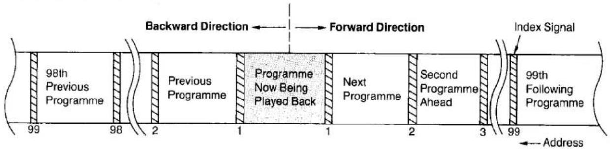
How to Count the Addresses
flowchart
graph LR
    A["98th Previous Programme"] --> B["Previous Programme"]
    B --> C["Programme Now Being Played Back"]
    C --> D["Next Programme"]
    D --> E["Second Programme Ahead"]
    E --> F["99th Following Programme"]
    F --> G["Index Signal"]
    style A fill:#f9f,stroke:#333
    style B fill:#f9f,stroke:#333
    style C fill:#ccf,stroke:#333
    style D fill:#ccf,stroke:#333
    style E fill:#ccf,stroke:#333
    style F fill:#f9f,stroke:#333
    style G fill:#f9f,stroke:#333
With the VHS Index Search function, up to 99 addresses (places where index signals are recorded) can be skipped to directly locate the beginning of the desired programme in both forward and reverse direction in the Fast Forward or Rewind mode.
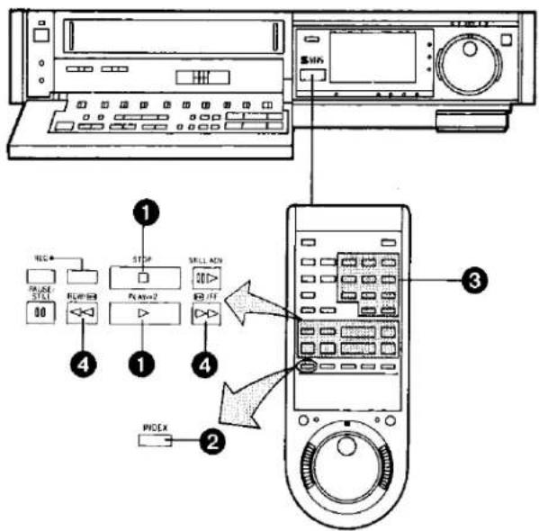
4 Press the Rewind ◀◀/Review ◀◀ or Fast Forward ▶▶/Cue ▶◀ Button to start the VHS Index Search function (the VTR will switch to the rewind or fast-forward mode).
- Every time an index signal (address) is skipped the number in the Address Indication decreases by one.
- When the preset address is reached, the Tape Counter Indication will appear in place of the Address Indication, and the normal playback will start.
-
To abort the Index Search function midway, press the Play/×2 or the Stop Button.
-
When activating the VHS Index Search function from the Still playback mode, the Playback will start when the selected programme is reached.
- If the VHS Index Search function is started extremely close to the beginning of the next programme (place where an address signal is recorded) or from the beginning of the tape, the first address may not be counted.
- If there are unrecorded parts on the tape, or if recordings have repeatedly been made on the same tape portion, the VHS Index Search function may not work correctly.
① Press the Play/×2 Button (▶) or Stop Button (■).
② Press the Index Button.
s

③ Input the number of programmes that you want to skip by pressing the number buttons.
s

- If you made a mistake, press the Index Button twice and input the correct number.
VHS INDEX SEARCH SYSTEM (CONT'D)
Recording of Index Signals
Index signals can be recorded during recording or on an already recorded tape.
Index signals will be recorded automatically in the following cases:
- At the tape position at which the Record Button is pressed to start recording.
- At the tape position at which a Timer Recording is started.
- At the tape position at which an OTR recording is started.

Recording Additional Index Signals During Recording
① Press the Index Button.
SP
s


2 Press the Write Button at a position that you want to mark with an index signal for easy, quick locating during playback.
SP
s
WRITE


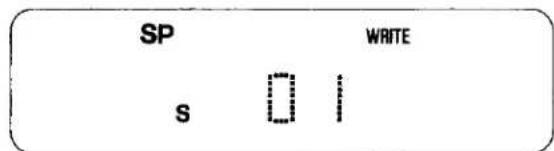
●The Write Indicator will be lit for a few seconds.
- If the Write Button is pressed while the VTR is in the recording pause mode, the pause mode is release and the recording starts.
● To change the Multi-Function Display from the Index indication mode to the Counter indication mode, press the Index Button.
Recording Index Signals on Already Recorded Tapes
① During playback, press the Pause/Still Button at the tape position that you want to mark with an index signal.
② Press the Index Button.
SP
s


③ Press the Write Button.
SP
s
WRITE


- When the Write Button is pressed, the tape will be rewound a little, and Playback will start and the index signal will be recorded.
●The Write Indicator will be lit for a few seconds. - When the recording of the index signal is completed, the Multi-Function Display changes over from the index indication to the counter indication mode, and the playback will automatically restart.
● Recording of index signals is not possible on cassettes with broken out tab.
- When recording index signals, take care that the interval between two index signals is at least 2 minutes (SP mode) and 5 minutes (LP mode).
- While the Write Indicator is lit, no other VTR functions can be operated.
Erasing Unnecessary Index Signals
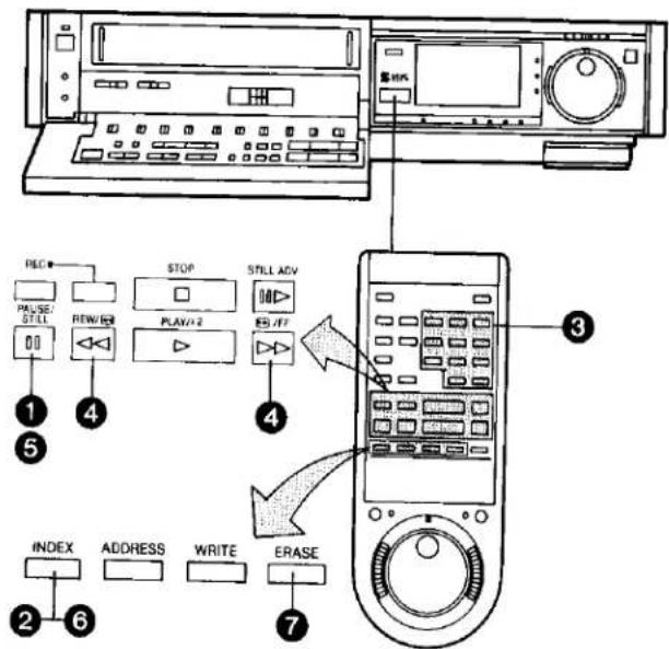
1 Press the Pause/Still Button while the VTR is in the playback mode.
② Press the Index Button.
③ Input with the Number Buttons the number of the index signal that you want to erase.
4 Press the Fast Forward or the Rewind Button. When the designated index signal is reached, the VTR changes over to playback.
5 Press the Pause/Still Button to put the VTR in the Still Playback mode.
6 Press the Index Button.
7 Press the Erase Button.
- When the Erase Button is pressed, the tape will be rewound a little before playback starts. When the index signal is reached, the Erase Indicator will light up for about 10 seconds to indicate that the index signal is being erased. When the erasing is completed, the playback will continue.
Index Repeat Playback
Selecting the Address for Index Repeat Playback

① Press the Play/×2 Button (▶) or the Stop Button (■).
② Press the Index Button.
③ Input with the Number Buttons the number of index signals that you want to skip in order to locate the index signal from which the Index Repeat Playback is to start.
- For example, press "3" to quickly advance to the fourth index signal from the present tape position.
4 Press the Rewind ◀◀/Review ◀◀ or Fast Forward ▶▶/Cue ▶◀ Button to start the VHS Index Search function (the VTR will switch to the rewind or fast forward mode).
Performing Index Repeat Playback

5 When the VTR is in the playback mode, press the Memory/Repeat/Search Button so that the "RS" Indicator lights up.

- When the next index signal is found, the tape will be rewound. When the index signal, where the playback is to start, is found, the playback will restart. In this way, automatically repeated playback can be performed for a tape portion as defined by the number of index signals that are skipped.
6 To stop the Index Repeat playback, press the Stop Button or press the Memory/Repeat/Search Button so that the "RS" Indicator goes out.
If Index Repeat playback is performed on a tape for long periods of time, the picture quality may become inferior.
VHS ADDRESS SEARCH SYSTEM

A desired tape position can quickly be accessed by inputting the number of the corresponding Address Signal.

Inputting the Number of the Address Signal
Example: Inputting the Address Signal "0123"
1 Press the Stop Button or the Play/×2 Button.
② Press the Address Button.
The Address Indicator on the VTR lights up.
③ Input the number of the Address Signal of the desired tape position with the Programme Position Selector Buttons.
4 Press the Fast Forward ▶▶/Cue ▶▶ Button to start the search for the desired tape position.
- To stop the interrupt the Address Signal Search function, press the Play/×2 Button or the Stop Button.
- To search for an Address Signal in reverse direction, press the Rewind ◀◀/Review ▶◀ Button.
During the VHS Address Signal Search
- Whenever an Address Signal is passed, its number will be indicated.
- When the selected Address Signal is reached, playback will start automatically.
●The fast forwarding or rewinding speed will be slightly slower than normal.
When starting the VHS Address Signal Search from the Still Playback Mode
When the selected Address Signal is reached, the VTR changes over to normal playback, and the Multi-Function Display changes back to the tape counter indication.
When the selected Address Signal Cannot Be Found
- When the tape reaches its end during the VHS Address Signal Search in forward direction, the Multi-Function Display changes back to the tape counter indication and the tape will be rewound automatically.
- When the tape reaches its end during the VHS Address Signal Search in reverse direction, the Address Indication will remain displayed and the tape will be stopped.
Finding out the Address Signal Number of a Certain Scene
Press the Address Button during fast-forwarding or re-winding of the tape.
- Whenever an Address Signal is passed, its number will be indicated in the Multi-Function Display.
● To change back to the tape counter indication, press the Address Button once more. - When the Address Number "0000" is written on the tape, playback will start at the position.
Writing Address Signals
Address Signals can be written both during recording and playback.

Writing Address Signals during Recording
Example: Writing Address Signal "0012".
① Press the Address Button. The Address Indicator on the VTR will lights up.
② Input the desired number with the Programme Position Selector Buttons.
③ Press the Write Button at the tape position which you want to mark with the set number.
SP
WRITE
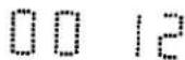
- To change back to the tape counter indication, press the Address Button once more.
- When writing an Address Signal while the VTR is in the recording pause mode, the pause mode will be cancelled, the recording will start and an Address Signal will be written.
●While an Address Signal is being written, the Write Indicator will be lit for several seconds.
Writing Address Signals during Playback
① Press the Pause/Still Button at the tape position, which you want to mark with an Address Signal. The VTR is in the Still Playback mode.
② Press the Address Button.
The Address Indicator on the VTR will lights up.
③ Input the desired number with the Programme Position Selector Buttons.
④ Press the Write Button.
SP
WRITE
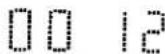
●While an Address Signal is being written, the Write Indicator lights up for several seconds.
●After the writing of the Address Signal is finished, the Multi-Function Display will change back to the tape counter indication.
● While the Write Indicator is lights up, no other functions are operable, and the sound on the normal sound track will be blanked for this duration.
- If the erasure prevention tab of the cassette is broken out, it is not possible to write Address Signals.
- Address Signals must be spaced at least 2 minutes (SP mode) and 5 minutes (LP mode).
VHS ADDRESS SEARCH SYSTEM (CONT'D)
Erasing Unnecessary Address Signals
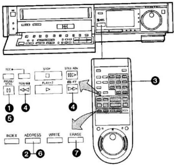
① Press the Pause/Still Button while the VTR is in the playback mode.
② Press the Address Button.
③ Input with the Number Buttons the number of the Address signal that you want to erase.
4 Press the Fast Forward or the Rewind Button. When the designated Address signal is reached, the VTR changes over to playback.
5 Press the Pause/Still Button to put the VTR in the Still Playback mode.
6 Press the Address Button.
7 Press the Erase Button.
•The Erase Indicator lights up.
- When the erasing is completed, the playback will continue.
Renumbering the Address Signals
It is possible to automatically and continuously renumber all Index and Address Signals on a tape starting with any desired number.
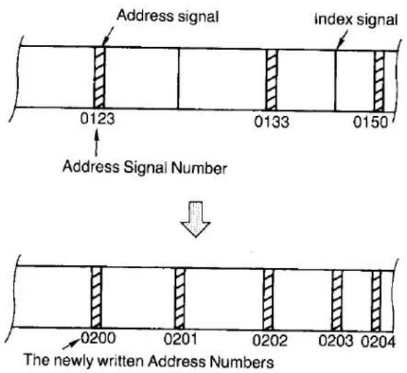
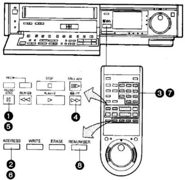
Example:
Changing all recorded Address Signals starting with the number "0123" (and all Index Signals) to new Address Signals starting with "0200".
① Press the Pause/Still Button during playback to change the VTR over to the Still Playback Mode.
② Press the Address Button.
③ Use the Programme Position Selector Buttons to select the Address Number to be located ("0123").
4 Press the Fast Forward ▶▶/Cue 🏠 Button to start the search.
5 Press the Pause/Still Button.
6 Press the Address Button.
⑦ Input the new Address Number "0200" with the Programme Position Selector Buttons.
8 Press the Renumber Button.
After Renumbering the Address Signals
- Such operations as fast-forward and rewinding should always be continued to the end of the tape.
- When the tape reaches its end, the tape will be rewound automatically.
- To interrupt the renumbering operation, press the Play/ ×2 Button or the Stop Button.
●During the renumbering operation, the Write Indicator lit and no other functions are operable. Also, the sound on the normal sound track will be blanked the time the Write Indicator is lit.
- If the erasure prevention tab of the cassette is broken out, the renumbering is not possible.
INTRO SCAN FUNCTION
How the Intro Scan Function Works...

flowchart
graph LR
    A["Programme"] --> B["Tape is fast-forwarded"]
    B --> C["Programme"]
    C --> D["Programme"]
    D --> E["Programme"]
    E --> F["Operation is repeated until tape reaches its end."]
    style A fill:#f9f,stroke:#333
    style B fill:#ccf,stroke:#333
    style C fill:#cfc,stroke:#333
    style D fill:#fcc,stroke:#333
    style E fill:#cff,stroke:#333
    style F fill:#ffc,stroke:#333
The Intro Scan function plays back the first 10 seconds of each programme (recorded with index signal) on a tape one after another. This is convenient for quick checking what programmes are on a tape, or to find the desired instalment of a TV series you have recorded on a tape.
Intro Scan Operation

● The Intro Scan function may not be activated for the first programme recorded close to the beginning of the tape.
●The Intro Scan function may not be activated, if the interval between programme starts is less than 5 minutes in the LP mode, or less than 2 minutes in the SP mode.
① Insert a video cassette.
(Put the VTR in the stop mode.)
② Press the Memory/Repeat/Search Button repeatedly until the "S" mark appears.
③ Press the Fast Forward ▶▶/Cue 📋 Button. (The Intro Scan starts.)
4 When the desired scene is reached, press the Play/×2 Button (▶).
TIME SEARCH
The Time Search function makes it possible to quickly advance the tape from any position by inputting the exact desired amount of playback time of the part that you want to skip.
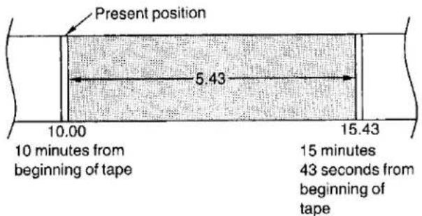
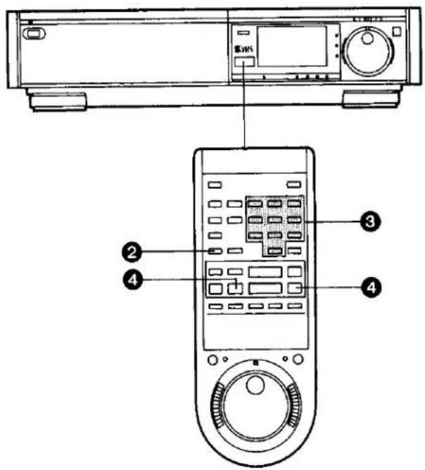
Time Search from the Stop Mode
1 Put the VTR in "STOP" mode.
2 Press the Time Search Button.
The indication in the Multi-Function Display changes as shown below.

③ Input the time of the desired scene.
● The time is input by pressing the number buttons in the order: hour, minute, second.
●The “-” indication will be counted as "0".
COUNT 0:05.43
4 Press the Fast Forward ▶▶/Cue 📄 Button or the Rewind ◀◀/Review 📋 Button.
The playback starts after rewinding or fast forwarding to the tape position of the designated time.
Time Search from the Play Mode
The operation is the same as that for the stop mode but in operation step 4, the Cue or Review (playback) is performed to the tape position of the designated time and the playback will then start.
If the time search function is activated during playback, a time of up to 9 minutes 59 seconds can be input.
●The numbers in the Tape Counter do not change during parts of the tape on which there is no recording.
- When the tape is inserted, the Tape Counter will automatically be reset to "0:00.00".
- When no time is input for the time search, a 2-minute tape segment is skipped and the playback will then resume.
If the time search function is activated during playback, but no time is input, a 30-second tape segment will be skipped and the playback will then resume.
CAMERA RECORDING

Preparation
- Connect the Video Camera via the Camera AC Adaptor to the VTR as shown in the illustration above.
- Set the Input Signal Selector to "Line/Audio".
- Insert a video cassette with the erasure prevention tab intact.
When a video cassette is already inside the VTR, press the VTR On/Off Switch to turn it on.
- Set the Tape Speed Selector to "SP" or "LP".
- Set the Audio Rec Level Control Selector to "AGC".
1 Turn the Camera AC Adaptor on and make the necessary adjustments on the camera.
Refer to the operating instructions of the camera you are using.
② Press the Record Button (●) on the VTR to start recording.
Avoid recording unwanted material:
Press the Pause/Still Button (■) on the VTR, and the recording will stop temporarily. To restart recording, press the Pause/Still Button (■), again.
3 Press the Stop Button (■) on the VTR to stop the recording.
- For playback of a tape that was recorded via a camera, select the audio track on which the sound from the camera microphone was recorded by pressing the corresponding Audio Output mode Selector Button on the Remote Controller.
- If you leave the VTR in the pause mode for more than 5 minutes, the VTR will stop automatically to protect the tape and the video heads.
- Even if the video camera is equipped with video recorder remote control functions, this VTR can not be remote-controlled from the camera.
Interval Recording Function
This recording function automatically repeats recording for approx. 2 seconds and pausing for approx. 4 seconds alternately. With this function, it is possible to make recordings, for example the opening of a rose, shortened into approx. 1/3th actual time. This makes it possible to record a 24-hour event on a single NV-E240 video cassette (in the LP mode).
● This function can be used not only for camera recording, but also for recording from TV programmes.
Try using this function for various kinds of creative recording.
① Press the Pause/Still Button (Ⅲ) during recording. (The VTR will be in the recording pause mode.)
② Press the Jog/Shuttle Button. (The Interval Recording will start.)
③ To stop the Interval Recording, press the Jog/Shuttle Button or the Pause/Still Button.
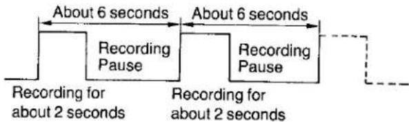



DUBBING (COPYING)
Dubbing (copying) from one video cassette to another.
If the VTR to Be Connected is Equipped with S-Video Socket
Perform the connection with the supplied S-Video Cable. This connection makes possible editing with better picture quality.
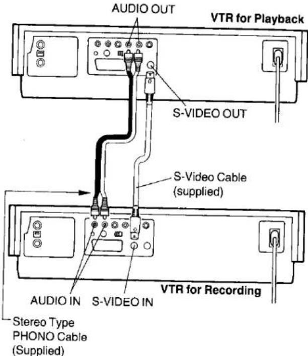
Preparation
● Make the necessary connections as shown in the connection diagram.
- Press the VTR On/Off Switches to turn both VTRs on.
- Set the Input Signal Selector to "S-VIDEO" (Recording VTR).
- Set the Audio Rec Level Control Selector to "AGC". (Recording VTR)
- Make sure that the Noise Filter/Edit Selector of both the recording and playback VTRs (if equipped) are in the "EDIT ON" position. Set these switches to "OFF" for ordinary use of the VTRs.
(The Noise Filter/Edit Selector is on the front panel.)
1 Place the recorded cassette in the playback VTR and a blank video cassette with the erasure prevention tab intact in the recording VTR.
② Press the Record Button (●) on the recording VTR.
3 Press the Play/x2 Button (▶) on the playback VTR.
4 Press the Stop Button (■) on both VTRs to stop the dubbing.
If both VTRs are equipped with a AV Connector

Preparation
● Make the necessary connections as shown in the connection diagram.
- Press the VTR On/Off Switches to turn both VTRs on.
- Set the Input Signal Selector to "AV".
- Make sure that the Noise Filter/Edit Selector of both the recording and playback VTRs (if equipped) are in the "EDIT ON" position. Set these switches to "OFF" for ordinary use of the VTRs.
(The Noise Filter/Edit Selector is on the front panel.)
The operations are the same as shown on the left.
The NV-FS100 is equipped with an Editing Control Socket. By connecting an optional Editing Controller (VW-EC300E) to this socket, such editing functions as Assemble Editing, Insert Editing and Audio Dubbing can be performed more quickly and efficiently between two VTRs. Regarding the availability of this Editing Controller, consult with your Panasonic video dealer.
DUBBING (COPYING) (CONT'D)
Connecting the VTR to another VTR which is not equipped with a AV socket
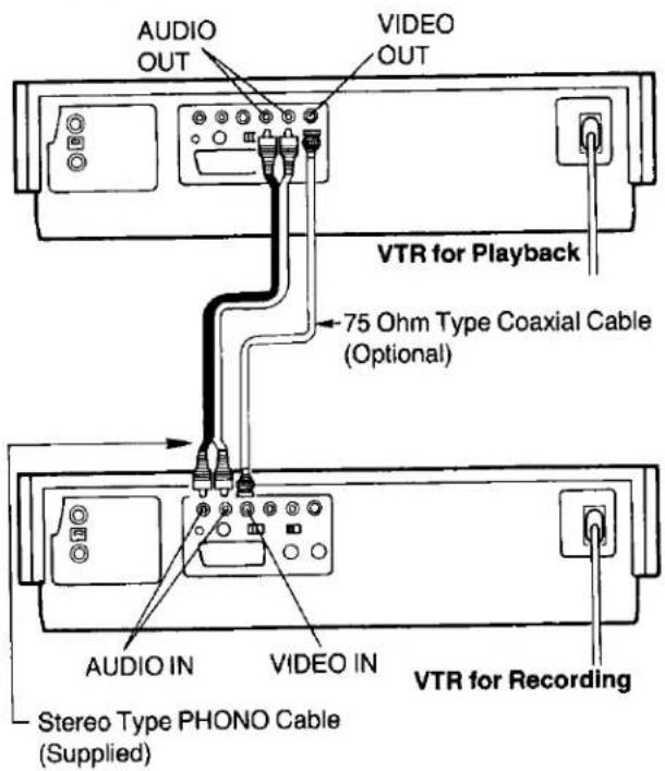
Preparation
● Make the necessary connections as shown in the connection diagram.
- Press the VTR On/Off Switches to turn both VTRs on.
- Set the Input Signal Selector to "Line/Audio". (Recording VTR)
- Set the Audio Rec Level Control Selector to "AGC". (Recording VTR)
- Make sure that the Noise Filter/Edit Selector of both the recording and playback VTRs (if equipped) are in the "EDIT ON" position. Set these switches to "OFF" for ordinary use of the VTRs.
(The Noise Filter/Edit Selector is on the front panel.)
1 Place the recorded cassette in the playback VTR and a blank video cassette with the erasure prevention tab intact in the recording VTR.
② Press the Record Button (●) on the recording VTR.
③ Press the Play/×2 Button (▶) on the playback VTR.
4 Press the Stop Button (■) on both VTRs to stop the dubbing.
-
To assure smooth, noiseless cuts when interrupting the recording, always use the Pause/Still Button (11).
● To obtain smooth cuts when starting the recording from the stop mode: -
Play back the last part of the previously recorded material to confirm its ending point, and then press the Pause/Still Button (■).
- Press the Record Button (●).
(The VTR is still in the pause mode.) - To start recording, press the Pause/Still Button (11) again.
●The picture quality of a re-recorded tape is not as good as that of the original.
Blank Search Function
The Blank Search function is convenient to quickly locate the end of the recorded part on the tape, for example, when you want to add another recording on the same tape.

① Press the Stop Button to put the VTR in the Stop mode.
② Press the Blank Search Button on the Remote Controller.
●The tape will be fast-forwarded to the blank (non-recorded) part, and the VTR will automatically change over to Still Playback at the end of the recorded part.
- When a non-recorded part is shorter than 5 seconds of fast-forwarding time, it cannot be detected, and the Blank Search function will continue to the end of the next recording.

natural_image
Completely black image with no visible content or text.
Connecting to a VHS/VHS-C Movie Equipped with Synchro Edit Function
It is possible to synchronize the playback start and stop of the VHS/VHS-C Movie with the recording start and stop of this VTR.
Preparation
●Make the necessary connections as shown in the connection diagram.
- Set the Edit Switch (Noise Filter/Edit Selector) on both the VHS/VHS-C Movie and on this VTR to "ON" (or "EDIT ON").
1 Put the VTR in the recording pause mode.
② Put the VHS/VHS-C Movie in the still playback mode.
- Put the Movie at the point where you want to start editing into the still playback mode.
③ Press the Pause/Still Button on the VTR.
● The VHS/VHS-C Movie changes over to the playback mode and the dubbing will start automatically.
To Leave Out Unwanted Scenes
① Press the Pause/Still Button on the VTR.
- The VTR changes over to the recording pause mode and the VHS/VHS-C Movie changes over to the still playback mode.
② Operate the VHS/VHS-C Movie to skip the unwanted scenes and then put it in the still playback mode again.
③ Press the Pause/Still Button on the VTR.
●The dubbing will restart.
To stop the dubbing, press the Stop Button on the VTR and then put the VHS/VHS-C Movie in the stop mode.
Control Dubbing

When an NV-FS100 is used as both recording and playback VTR, the connection shown above makes possible dubbing of index signals and address signals, too. The operation is the same as for ordinary dubbing.
INSERT EDITING
When this type of editing is done, the picture and the sound are recorded on the tape as shown below. However, if no new sound is input, the original sound remains only on the "normal" audio track of the tape because the original Hi-Fi sound will always be erased during insert editing.
Video and Audio Track Recording Pattern


Preparation
- Insert a video cassette with the erasure prevention tab intact.
- When performing insert editing from another VTR, set the Noise Filter/Edit Selector to "EDIT ON".
- Set the Input Signal Selector according to the type of insert editing to be performed.
"LINE/AUDIO": When inserting picture and sound from equipment connected to the Video Input Socket and the Audio Input Sockets on the rear of this VTR.
"TUNER": When inserting scenes from a TV programme.
"S-VIDEO": When inserting picture and sound from equipment connected to the S-Video Input Socket and the Audio Input Sockets on the rear of this VTR.
① Press the Jog/Shuttle Button.
② Set the S-VHS Selector according to the S-VHS Indicator.
When the S-VHS indicator is
lit Set to "ON".
not lit. Set to "OFF".
3 Use the Shuttle Ring and the Jog Dial to search for the point where you want the editing to end (end point), and put the VTR into the still playback mode.
4 Press the Reset Button on the Remote Controller to reset the Tape Counter to "0:00.00".
5 Use the Shuttle Ring and the Jog Dial to search for the point where you want the editing to start (start point), and put the VTR into the still playback mode.
6 Press the Insert Editing Button. (The Insert Editing Indicator lights up.)
7 After the picture to be inserted is prepared, press the Pause/Still Button (Ⅱ). (The insert editing will start.)
8 Press the Stop Button as soon as the Tape Counter shows "0:00.00".
- It is not necessary to operate the Tape Speed Selector.
●The picture quality of an inserted part is always somewhat inferior to that of the original.
●Avoid performing insert editing repeatedly on the same part of the tape because the picture quality of that part becomes inferior.
●The inserted picture may contain slight colour noise or the colours may be unstable.
Playback of a Tape on Which Insert Editing Was Performed
The sound inserted during insert editing is recorded on the Hi-Fi sound tracks (STEREO, LEFT, RIGHT). If the normal sound track is selected, the original sound before the insert editing will be heard. Select the desired sound with the Audio Output Mode Selector on the Remote Controller.
Hi-Fi/Normal Mix Switch
Set this switch to "On", if you want both the "Hi-Fi" sound and the "normal" sound to be played back mixed together.
● The mixed sound may not be very clear.
Always set this switch to "Off", except when playing back a tape on which the insert editing or audio dubbing was performed.
AUDIO DUBBING
Note that the original sound on the "normal" (mono) sound track will be completely erased during audio dubbing.

Preparation
- Set the Input Signal Selector to "Line/Audio".
- Insert a video cassette with the erasure prevention tab intact.
When a video cassette is already inside the VTR, press the VTR On/Off Switch to turn it on.
●Turn the TV set on and select the video playback channel.
- Select the "normal" (mono) sound track by repeatedly pressing the Audio Output Mode Selector on the Remote Controller until the Audio Output Mode Indicators "Left" and "Right" are no longer lit.
1 Press the Play/×2 Button (▶) to locate the point where you want to start the audio dubbing.
② Press the Pause/Still Button (Ⅲ) at the exact point where you want to start the audio dubbing.
③ Press the Audio Dubbing Button (the indicator will light up).
AUDIO DUB
AUDIO DUB

O
4 Press the Pause/Still Button (I) once again to release the tape from pause, and at the same time start the operation of the audio source. The audio dubbing will start.
5 Press the Stop Button (■) to stop the audio dubbing.
- When a microphone is used for dubbing, do not place it near the speaker of your TV to prevent howling noise (acoustic feedback).
- If the erasure prevention tab of the cassette is missing, no audio dubbing can be made.
Playback of a Tape on Which Audio Dubbing Was Performed
The sound inserted during audio dubbing is recorded on the normal sound track. If the Hi-Fi sound tracks (STEREO, LEFT, RIGHT) are selected, the original sound (before the audio dubbing) will be heard.
Hi-Fi/Normal Mix Switch
Set this switch to "On", if you want both the "Hi-Fi" sound and "normal" sound to be played back mixed together.
●The mixed sound may not be very clear.
Always set this switch to "Off", except when playing back a tape on which the insert editing or audio dubbing was performed.
BEFORE REQUESTING SERVICE
Before requesting service, check the following points once again.
| SYMPTOM | CAUSE | REMEDY |
| Power doesn't turn on. | Mains lead is not connected. | Connect mains lead to mains outlet. |
| The Timer Record Function is set to "On". | Set the Timer Record Function to "Off". | |
| Power is on but unit doesn't operate. | Safety devices are operating. | Turn off the VTR On/Off Switch, disconnect mains cord from outlet, then reconnect mains cord to mains outlet and turn on the VTR On/Off Switch again. |
| TV programmes cannot be recorded. | Connection of aerial lead is not correct. | Connect aerial lead correctly. |
| Reception channel is not properly tuned. | Tune reception channel. | |
| The Input Signal Selector is not set correctly. | Set the Input Signal Selector to "Tuner". | |
| OTR Function (One-Touch Timer Recording) cannot be performed. | Clock is flashing "0:00". | Set clock to present time. |
| Unattended timer recording cannot be performed. | Recording start or recording stop time setting is incorrect. | Set recording start and recording stop time correctly. |
| The Timer Record Function is set to "Off". | Set the Timer Record Function to "On". | |
| Clock shows incorrect time. | Adjust clock to present time. | |
| Clock is flashing "0:00". | Set clock time and perform timer setting. | |
| The Input Signal Selector is not set to "Tuner". | Set the Input Signal Selector to "Tuner". | |
| If you attempt to carry out Recording, Timer Recording, or OTR, the cassette will be automatically ejected. | Accidental erasure prevention tab on the cassette is broken out. | Cover tab hole with adhesive tape. |
| Recording via external input terminals cannot be performed. | The Input Signal Selector is not set correctly. | Set the Input Signal Selector to "Line/Audio". |
| Recorded programmes with two-channel sound (stereo, oilingual or Simulcast) can not be played back. | Setting of the Audio Output Mode Selector Button on the Remote Controller is not correct. | Press the Audio Output Mode Selector Button on the Remote Controller to select the desired audio output mode. (See page 29.) |
| Playback picture is not in colour.Playback picture has large amounts of "snow". | Reception channel was not adjusted correctly during recording. | Readjust reception channel correctly. |
| TV set is not properly tuned to the video playback channel of the VTR. | Properly tune the TV set to the video playback channel of the VTR. | |
| The video heads are clogged with dirt. | Consult qualified service personnel. | |
| The video heads are abraded. | Consult qualified service personnel. | |
| Tape is old and/or defective. | Use new tape. | |
| In case of signal input via AV Connector, the picture is not in colour. | The Normal/Y/C Selector is not set correctly. | Set the Normal/Y/C Connector to the correct position. |
| Remote Controller (Digital Scanner) does not work. | Remote Controller (Digital Scanner) is not being pointed at Infra-red Receiver Window on the VTR. | Point the Remote Controller (Digital Scanner) at Infra-redReceiver Window on the VTR. |
| Distance is too far. | Use the Remote Controller within 7 m from the VTR. | |
| An obstacle is between Remote Controller (Digital Scanner) and VTR. | Remove obstacle. | |
| Batteries are exhausted. | Replace batteries. | |
| Battery polarities (+,-) are reversed. | Insert batteries correctly. | |
| Bar code reading with Digital Scanner is impossible. | The Scanner is in the power-saving standby condition. | Set the Digital Scanner On/Off Switch to "OFF" and then to "ON" again . |
| The bar code has been traced too slowly. | Trace the bar code quickly. | |
| The bar code was not traced all the way from the Small Box past the last bar. | Trace the bar code correctly. | |
| The bar code was not traced straight. | Trace the bar code straight from left to right. | |
| Transmission from the Digital Scanner to the VTR cannot be performed. | The VTR is turned off. | Turn the VTR on. |
| The VTR is in an operation mode. | Put the VTR into the stop mode. | |
| There is no unoccupied timer programme number left. | A maximum of 8 timer recordings can be programmed at the same time. | |
| Reading a bar code was not followed by a"beep" sound from the Digital Scanner. | Perform the bar code reading again. | |
| The transmission was not followed by a repeated "beep" sound from the VTR. | Keep pressing the Transmit Button until the confirmation sound is heard. |
SPECIFICATIONS
NV-FS100B... (U.K. model)
Power Source:
Power Consumption:
240 V AC 50-60 Hz
Approx. 40 watts
is the safety information
Video Recording System:
Video Heads:
Tape Speed:
Tape Format:
Record/Playback Time:
FF/REW Time:
VIDEO
Television System:
Modulation System:
Input Level:
Output Level:
2 rotary heads, helical scanning system
4 heads
SP, 23.39 mm/sec.
LP: 11.7 mm/sec
SYHS VHS tape
SP: 240 min, with NV-E240 VHS
LP: 480 min. with NV-E240 WIS
Less than 2.5 min, with NV-E180
SP: 180 min. with NV-SE180 SYHS
LP: 360 min. with NV-SE180 SIVHS
CCIR, 625 lines, 50 fields, PAL colour signal
Luminance, FM azimuth recording
Colour signal, converted subcarrier phase shift recording
VIDEO IN (BNC): 1.0 Vp-p.
AV: 1.0 Vp-p
S-VIDEO IN: Y 1.0 Vp-p
C 0.3 Vp-p
VIDEO OUT (BNC): 1.0 Vp-n
AV. 1.0 Vp-p
S-VIDEO OUT, Y: 1.0 Vp-p.
C 0.3 Vp-p
HF Modulated; UHF channel 36 (±4)
75 ohm. unbalanced
75 ohm, unbalanced
75 ohm, unbalanced
75 ohm, unbalanced
75 ohm, unbalanced
75 ohm, unbalanced
75 ohm, unbalanced
75 ohm, unbalacned
75 ohm, unbalanced
AUDIO
Input Level:
Output Level:
Audio Track:
Video Horizontal Resolution:
Dynamic Range:
Audio Frequency Response:
Wow and Flutter
Operating Temperature:
Operating Humidity:
Weight:
Dimensions:
Standard Accessories:
AUDIO IN (PHOND):
AV
MICROPHONE: -70 dB
AUDIO OUT (PHONO);
AV-6 dB
HEADPHONES: 30 dB
1-track (Normal-mono only), 2 channels (Hi-Fi sound-stereo)
Colour: more than 240-lines (VHS/SP)
more than 400 lines (S-VHS/S-Video Socket)
Audio: more than 90 dB (Hi-Fi) audio track
20 Hz-20 kHz (Hi-Fi audio track)
0.005% Wrms/Hi-Fi
5°C-40°C
35%-80%
8.5kg
460 (W)×109 (H)×404 (D) mm
1pc. DIN-DIN Coaxial Cable
1pc. Remote Controller
3pcs. "R6" size batteries
2pcs Stereo type Phono Cables
pc, Digital Scanner (with Programming Sheet)
4pos. "ROS" size batteries (for Digital Scanner)
pc. AC Mains Lead
pc. S-Video Cable
more than 50 kohm, unbalanced
more than 10 kohm, unbalanced
less than 1 kohm unbalanced
less than 1 kohm, unbalanced
8ohm

Printed in Japan
VQT3382
F0489M1079-2000⑧
Weight and dimensions shown are approximate.
Specifications are subject to change without notice.
Matsushita Electric Industrial Co., Ltd.
Central P.O. Box 288, Osaka 530-91, Japan
- Panasonic
- CONTENTS
- Page
- Back
- IMPORTANT
- WARNING
- FOR YOUR SAFETY
- ■ DO NOT REMOVE OUTER COVER.
- ■ AC MAINS LEAD CONNECTION
- HQ (High Quality) Picture System
- CAUTIONS
- Cassette Compartment Door
- Avoid Sudden Changes in Temperature
- Humidity and Dust
- Do Not Obstruct the Ventilation Holes
- Keep away from High Temperature
- Keep Magnets away
- No Fingers or Other Objects Inside
- Keep Water away
- Cleaning the VTR
- Stacking
- Video Head Clogging
- Lightning
- Condensation may forms in the VTR If:
- Note:
- CONTROLS AND COMPONENTS
- CONTROLS AND COMPONENTS (CONT'D)
- INFRA-RED REMOTE CONTROLLER AND DIGITAL SCANNER
- How to Operate the Digital Scanner
- Tracing the Bar Codes
- INFRA-RED REMOTE CONTROLLER AND DIGITAL SCANNER (CONT'D)
- Power Source for the Remote Controller (Digital Scanner)
- CAUTION FOR BATTERY REPLACEMENT
- Load the batteries as follows:
- Recommendation
- S-VHS FORMAT
- S-VHS Selector
- Using VHS Cassettes
- Playback of S-VHS and VHS Cassettes
- S (SEPARATE)-VIDEO SOCKET, INSTALLATION
- INSTALLATION
- TUNING THE TV SET TO THE VIDEO PLAYBACK CHANNEL
- RF Signal Level Switch:
- Comb Filter/Test Signal Switch
- SETTING THE TUNER IN THE VTR
- Preparation
- Channel Selection with the Remote Controller
- SETTING THE CLOCK TO THE PRESENT TIME
- For Example: Set the clock for Sunday, October 10, 1999, 9:10
- SETTING THE CLOCK TO THE PRESENT TIME (CONT'D)
- THE VIDEO CASSETTE
- Inserting a Video Cassette (Auto Operation)
- Notes:
- Removing a Video Cassette
- Auto Operation
- Auto VTR On
- Auto Play
- Auto Rewind
- Auto Eject
- VTR-Off Eject
- Rewind Auto Shut Off
- Auto Timer Recording Standby
- PLAYBACK
- Normal Playback
- ② To Finish Playback
- ③ Super Still Playback
- Cue Playback
- Review Playback
- Double Speed Playback
- Super Still Advance Playback
- PLAYBACK (CONT'D)
- Using the Shuttle Ring
- Still and Slow Playback
- Using the Jog Dial
- Turning the Jog Dial
- Slow Tracking Control
- Repeat Playback between the Beginning of the Tape and the End of the Recorded Part
- Rewind and Fast Forward
- Lap Time Counter
- Auto Cue and Play
- Noise Filter/Edit Selector
- Indication of the Remaining Tape Time
- Tape Select Switch
- Digital Tracking Selector
- Digital Tracking
- Manual Tracking
- Memory/Repeat/Search Button
- Clock/Counter Selector
- Memory Function
- Search Lock Indication
- Monitoring Function
- RECORDING FROM A TV BROADCAST SIGNAL
- To Finish the Recording
- If You Wish to Avoid Recording Unwanted Material
- Recording One TV Programme While Watching Another
- Tape Speed Selector (SP/LP)
- Manual Adjustment of the Audio Recording Level
- NICAM SYSTEM
- Recording of a NICAM stereo programme
- Recording of a NICAM dual-sound track programme
- Recording of a NICAM monaural programme
- NICAM SYSTEM (CONT'D)
- Nicam/Mono Switch
- HI-FI AUDIO SYSTEM
- Recording of Simulcast Sound
- Playback (or Monitoring during Recording)
- SUPER OTR FUNCTION (ONE-TOUCH TIMER RECORDING)
- SUPER OTR FUNCTION (ONE-TOUCH TIMER RECORDING) (CONT'D)
- OTR Function with Immediate Start
- TIMER RECORDING
- For Example:
- TIMER RECORDING (CONT'D)
- For Everyweek Recording
- For Everyday Recording
- To Confirm the Programme of a Timer Recording
- To Cancel a Timer Recording
- TIMER RECORDING BY USING THE DIGITAL SCANNER
- Transmit the Programming Data
- TIMER ON/OFF
- For Programming More Than One Timer Recording in Succession
- To Cancel a Programmed Timer Recording
- VHS INDEX SEARCH SYSTEM
- VHS INDEX SEARCH SYSTEM (CONT'D)
- Recording of Index Signals
- Recording Additional Index Signals During Recording
- Recording Index Signals on Already Recorded Tapes
- VHS ADDRESS SEARCH SYSTEM
- Inputting the Number of the Address Signal
- During the VHS Address Signal Search
- When starting the VHS Address Signal Search from the Still Playback Mode
- When the selected Address Signal Cannot Be Found
- Finding out the Address Signal Number of a Certain Scene
- Writing Address Signals
- Writing Address Signals during Recording
- Writing Address Signals during Playback
- VHS ADDRESS SEARCH SYSTEM (CONT'D)
- Renumbering the Address Signals
- Example:
- After Renumbering the Address Signals
- INTRO SCAN FUNCTION
- TIME SEARCH
- Time Search from the Stop Mode
- Time Search from the Play Mode
- CAMERA RECORDING
- Interval Recording Function
- DUBBING (COPYING)
- If the VTR to Be Connected is Equipped with S-Video Socket
- DUBBING (COPYING) (CONT'D)
- Blank Search Function
- Connecting to a VHS/VHS-C Movie Equipped with Synchro Edit Function
- To Leave Out Unwanted Scenes
- INSERT EDITING
- Playback of a Tape on Which Insert Editing Was Performed
- Hi-Fi/Normal Mix Switch
- AUDIO DUBBING
- Playback of a Tape on Which Audio Dubbing Was Performed
- BEFORE REQUESTING SERVICE
- SPECIFICATIONS
- is the safety information
Marque : PANASONIC
Modèle : NV-FS100B
Catégorie : Magnétoscope