
NV-FS200B - Magnétoscope PANASONIC - Notice d'utilisation et mode d'emploi gratuit
Retrouvez gratuitement la notice de l'appareil NV-FS200B PANASONIC au format PDF.


| Type de produit | Magnétoscope VHS |
| Marque | Panasonic |
| Modèle | NV-FS200B |
| Dimensions (L x P x H) | 430 x 250 x 90 mm |
| Poids | 3,8 kg |
| Alimentation | 220-240 V, 50 Hz |
| Consommation électrique | 20 W (en fonctionnement) |
| Fonctions principales | Lecture, enregistrement, avance rapide, rembobinage, pause, arrêt sur image, recherche de scène, enregistrement programmé |
| Enregistrement programmé | Jusqu'à 8 programmes par mois, avec sélection de date, heure et chaîne |
| Vitesses de bande | SP (2h), LP (4h), EP (6h) en mode PAL |
| Connectiques | Entrée antenne coaxial, prise péritel (SCART) pour audio/vidéo, sorties audio RCA |
| Entretien et nettoyage | Nettoyage régulier des têtes avec une cassette de nettoyage; éviter la poussière et l'humidité |
| Sécurité | Protection enfant (verrouillage des touches), arrêt automatique en fin de bande, ventilation pour éviter surchauffe |
| Pièces détachées et réparabilité | Têtes de lecture, courroies, cartes électroniques; réparation possible auprès de centres agréés Panasonic |
| Informations générales | Magnétoscope VHS standard compatible PAL/SECAM, avec enregistrement Hi-Fi stéréo |
FOIRE AUX QUESTIONS - NV-FS200B PANASONIC
Questions des utilisateurs sur NV-FS200B PANASONIC
0 question sur cet appareil. Repondez a celles que vous connaissez ou posez la votre.
Poser une nouvelle question sur cet appareil
Téléchargez la notice de votre Magnétoscope au format PDF gratuitement ! Retrouvez votre notice NV-FS200B - PANASONIC et reprennez votre appareil électronique en main. Sur cette page sont publiés tous les documents nécessaires à l'utilisation de votre appareil NV-FS200B de la marque PANASONIC.
MODE D'EMPLOI NV-FS200B PANASONIC

SVHS
VHS PAL
Before attempting to connect, operate
or adjust this product, please read
these instructions completely
114619-1
- 2017年,公司与上海浦东发展银行股份有限公司签订了《关于使用部分闲置募集资金进行现金管理的协议》。
Dear Customer
May we take this opportunity to thank you for purchasing this Panasonic Video Cassette Recorder.
We would particularly advise that you carefully study the Operating Instructions before attempting to operate the unit and that you note the listed precautions.

natural_image
Line drawing of a person sitting on a couch watching TV in a living room with a potted plant (no text or symbols)Information for Your Safety
IMPORTANT
Your attention is drawn to the fact that recording of pre-recorded tapes or discs or other published or broadcast material may infringe copyright laws.
WARNING
TO REDUCE THE RISK OF FIRE OR SHOCK HAZARD, DO NOT EXPOSE THIS EQUIPMENT TO RAIN OR MOISTURE.
This apparatus was produced to BS 800.
FOR YOUR SAFETY
■ DO NOT REMOVE OUTER COVER.
To prevent electric shock, do not remove cover. No user serviceable parts inside. Refer servicing to qualified service personnel.
■ AC MAINS LEAD CONNECTION
The wires in the mains lead of this apparatus are coloured in accordance with the following code.
Important

BLUE ..... NEUTRAL BROWN ..... LIVE
Mains Lead
As the colours of the wires in the mains lead may not correspond with the coloured markings identifying the terminals in your plug proceed as follows: The wire which is coloured BLUE must be connected to the terminal which is marked with the letter N or coloured BLACK. The wire which is coloured BROWN must be connected to the terminal which is marked with the letter L or coloured RED.
Under no circumstances must either of the above wires be connected to the earth terminal of a three pin plug.
HD (High Quality) Picture System
Video recorders carrying the HQ symbol mark feature the new VHS High Quality Picture System. This system assures complete compatibility with VTRs that use the conventional VHS system.
Contents
Setting up
Connections 8
Tuning the TV into your VTR 11
Storing TV Broadcasts into your VTR 12
Setting the Clock of the VTR 13
Controls, Indicators and Connection Sockets .... 14
The Video Cassette 23
Basic Operations
Playback 26
On-the-spot Recording 28
One-Touch Timer Recording (OTR) 30
Advanced Operations
Timer Recording 34
Search Function 36
•VHS Index Search System 36
•Time Search 37
Editing 38
●Copy Editing 38
●Assembly Editing 40
●Synchronized Editing 41
- Insert Editing 42
•Audio Dubbing 43
Other Functions 44
●The NICAM Broadcast System 44
●Automatic Features 45
•NTSC Playback 46
Bar Code Operation 47
- Scanner Preparation 47
- Setting the Clock 48
●Timer Recording 50
Helpful Hints
Before Requesting Service 54
Precautions 58
Specifications 59
Quick Reference 60
Unpacking
Check and identify the supplied accessories, and then set up this VTR after reading Setting Up.

natural_image
Line drawing of a vintage computer monitor with control panel and buttons (no text or symbols)
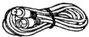
RF coaxial cable for connecting between this VTR and a TV (1 pc.) VJA0376-1 or VJA0376-B

AC mains lead (1 pc.) VJA0688 or VJA0714

natural_image
Illustration of a coiled cable with two connectors (no text or symbols)
Audio Cable (1 pc.)


S-Video Cable (1 pc.)


Remote controller (1 pc.) VEQ1391

natural_image
Line drawing of a remote control device with buttons and dials (no text or symbols)
Digital scanner (1 pc.) VEQ1326


Batteries for the remote controller (3 pcs.) UM3 or R6 type


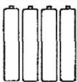
Batteries for the digital scanner (4 pcs.) UM4 or R03 type

Programming sheet (1 pc.) VQC1860

How to use these operating instructions
The illustrations are mainly of the VTR, but any button on the remote controller with the same name has the same function as that on the VTR.
The numbers in the illustrations and in the descriptive sentences on each page indicate the sequence of operating steps.
In this way, you can relate a particular control to an action and, where appropriate, to a visual display by the same number.

Setting Up
Connections
This tells you how to connect with an aerial, TV, etc.
Tuning the TV into your VTR
The VTR supplies signal to the TV set via the RF coaxial cable on channel 36 of the UK broadcasting system. Your TV must be tuned into this channel in order to view the VTR playback picture.
If connection to the TV includes the 21 pin scart cable or S-Video/Audio cable, the playback picture can be viewed by selecting AV on your TV.
The RF coaxia: cable must still be connected as shown on page 9, but the TV need not be tuned to channel 36.
Storing TV Broadcasts into your VTR
The VTR is fitted with its own TV tuner (just like a normal TV set) and can be tuned to receive up to 99 TV broadcast stations.
Setting the Clock of the VTR
The built-in clock is used to activate the timer for automatic recording and must be set to the correct time.
Controls, Indicators and Connection Sockets
This gives a detailed explanation of the function of each button, switch, indicator and connection socket.
The Video Cassette
Connections
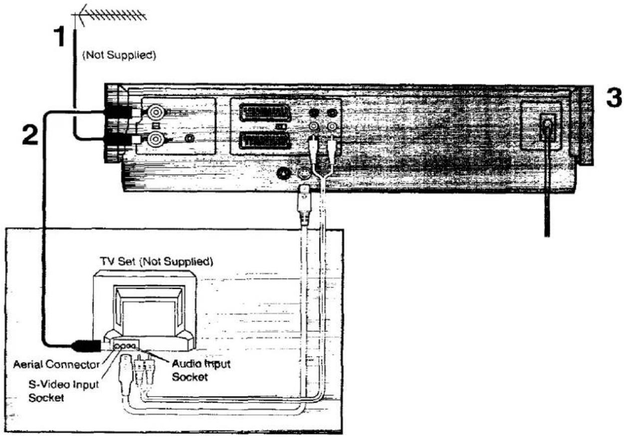
Basic Connections

The following connections are required to record and play back the VTR through a TV set:
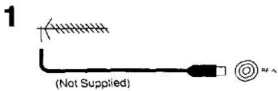
Connect an external aerial to RF IN.

Connect RF OUT to the TV aerial connector ( ).

Connect the AC mains lead to the AC mains socket.
Additional Connections
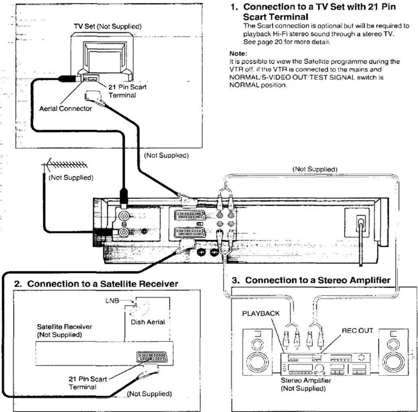
1. Connection to a TV Set with 21 Pin Scart Terminal
The Scarl connection is optional but will be required to playback Hi-Fi stereo sound through a stereo TV. See page 20 for more details.
Note: It is possible to view the Satellite programme during the VTR off, if the VTR is connected to the mains and NORMAL'S-VIDEO OUT:TEST SIGNAL switch is NORMAL position.
4. Connection to a TV Set with S-Video Socket
This VTR uses the S-VHS format which makes it possible to obtain high resolution and high picture quality by using the high-performance S-VHS video cassette tapes.
The conventional video sockets of VTRs outputs/inputs a combination of the luminance signal (Y) the monochrome part of the picture and colour signal (C) which are recorded on the video tape. The new S (Separate)-Video Socket allows separate transmission of these two signals to a TV set in order to obtain clearer pictures.
The connection with the S-Video Cable can also be used for playback of a tape that was recorded in the conventional VHS system. The "S" in the "S-Video Socket" stands for "SEPARATED Y/C" not for "S-VHS".
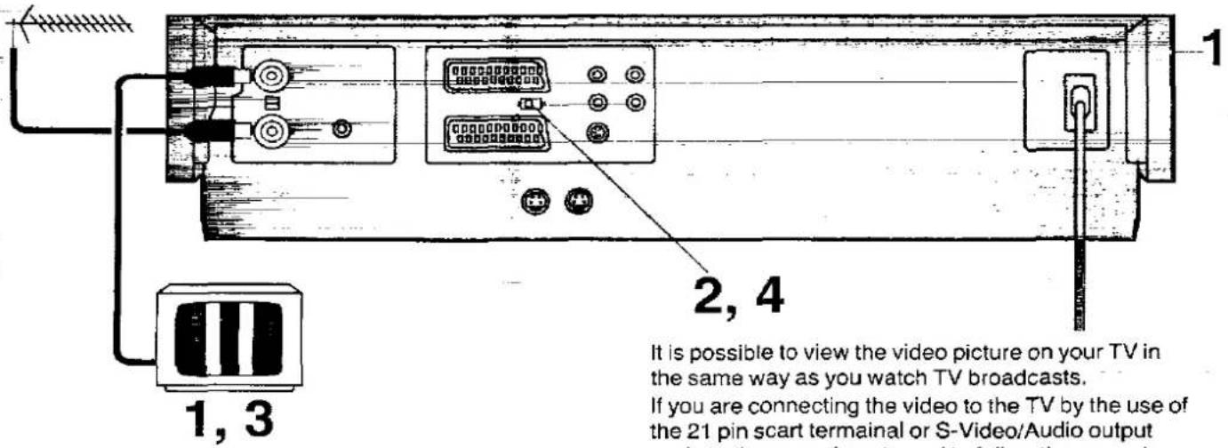
Operations
1

Turn the TV on. The VTR should also be turned on by pressing VTR on the front panel of the video.
2

To generate a test pattern, set NORMAL/S-VIDEO OUT/TEST SIGNAL located on the rear of the video to TEST SIGNAL.
3

Set the TV to an unused position which you wish to use for your video playback E.G. position 5. Follow the tuning procedure for your TV until you can view the TEST BARS.
4

After tuning the test bars into the TV, set NORMAL/S-VIDEO OUT/TEST SIGNAL to NORMAL. Position 5 is now your video channel.
Note:
The TEST signal is transmitted on channel 36 of the UK broadcasting channels. If you are encountering interference from another broadcast on the video channel, you may readjust to a free channel by using the CH ADJ. screw which is located on the rear of the VTR.
Please note that if the CH ADJ. screw is used then you will have to return your TV to the TEST signal as in item 2 to 4 above.
Storing TV Broadcasts into your VTR

Introduction
The VTR is fitted with its own tuner (just like a normal TV set) and can be pre-set to receive up to 99 TV broadcast stations.
Preparation
Confirm the TV is on and the VTR viewing channel is selected.
| Operations | Display Symbols | ||
| 1 | PRESETNORMAL | First, press PRESET/NORMAL. | |
| 2 |  |  | Select station position 1 for tuning using . |
| 3 |  | 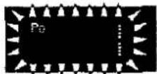 | To search for the TV station press TRACKING/V-LOCK + or -; at this point the VTR will start to search for a broadcast TV station. If the required TV broadcast is not displayed, again press + or -. |
| 4 |  |  | To memorize the broadcast station, press STORE.•To memorize the other stations repeat steps 2 to 4. |
| 5 | PRESETNORMAL | Once all the broadcast stations are memorized into their appropriate station positions, press PRESET/NORMAL once again to set the VTR to normal operative mode. | |
Note:
While tuning, your video may lock onto several weak stations from distant transmitters. Should this occur press TRACKING/V-LOCK + or - again until a strong station is received.
Setting the Clock of the VTR
Storing TV Broadcasts into your VTR
Setting the Clock of the VTR

natural_image
Line drawing of a computer setup with front panel, rear panel, and control panel (no text or symbols visible)1,7 2\~6
In addition to setting the VTR clock from the digital scanner, it can also be set directly from the VTR. The built-in digital clock employs the 24-hour system.
Preparation
Turn ON the VTR.
For Example:
Set the clock for Sunday, October 10, 1999, 20:15.
| Operations | Display Symbols | |||
| 1 | CLOCK |  | Press CLOCK. | |
| 2 | - TRACKING/V-LOCK + | → NEXT | Set the year by pressing TRACKING/V-LOCK + or -, and then press NEXT. | |
| 3 | - TRACKING/V-LOCK + | → NEXT | Set the month by pressing TRACKING/V-LOCK + or -, and then press NEXT. | |
| 4 | - TRACKING/V-LOCK + | → NEXT | Set the date by pressing TRACKING/V-LOCK + or -, and then press NEXT. | |
| 5 | - TRACKING/V-LOCK + | → NEXT | Set the hour by pressing TRACKING/V-LOCK + or -, and then press NEXT. | |
| 6 | - TRACKING/V-LOCK + | Set the minute by pressing TRACKING/V-LOCK + or -. | ||
| 7 | CLOCK | To start the clock from this setting, press CLOCK. | ||
Note:
The clock operates for at least 60 minutes, by its back up system in the event of power failure.
Controls, Indicators and Connection Sockets
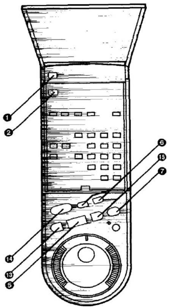
Basic Controls
① VTR (Video Cassette Recorder On/Off)
The VTR is turned on and off by pressing this button. The indicator above the button is lit when the VTR is on.
- The VTR is also automatically turned on if a cassette tape is inserted. However, it is not automatically turned off by ejecting the cassette tape.
- The VTR is also temporarily turned on if EJECT is pressed to eject a cassette tape. In this case, it is automatically turned off afterwards.
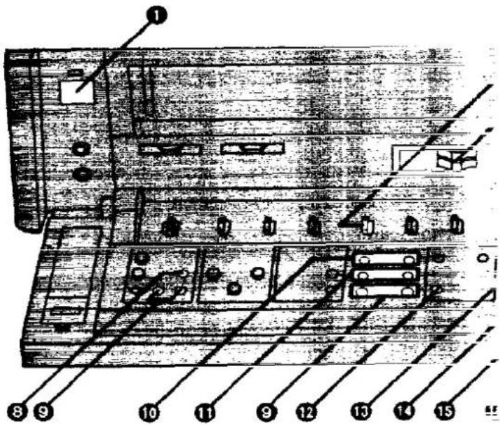
2 REMOTE MODE (VTR 1/2)
VTR 1: Set at this position on both the VTR and remote controller for normal use with one VTR.
VTR 2: Set at this position when using two Panasonic VTRs.
This allows the remote controller to be set for operating VTR 1 or VTR 2.
③ HI-FI REC LEVEL
Use this control for adjusting the recording level to peak at +4 dB on the recording level indicator.
4 S-VHS
When making a recording on an S-VHS cassette tape, select the desired recording format with this switch.
ON: The recording will be made in the S-VHS format.
The S-VHS Indicator lights up.
OFF: The recording will be made in the VHS format. The S-VHS indicator does not light up (It is possible to make a recording on an S-VHS cassette tape in the VHS format, for example, in order to play back the tape on another VHS VTR.)
- When using VHS cassettes. The recording is made in the VHS format irrespective of the position to which this switch is set.
- During playback, It is not necessary to operate this switch.
- When a tape which was recorded in the S-VHS format is played back on a conventional VHS VTR, it is not possible to obtain a playback picture.
5 PLAY
Press this button to start playback. " > " is lit.
6 REC
Press this button on the VTR to start a recording. The two recording buttons on the remote controller have to be pressed together for the same function "I>REC" is lit.

7 PAUSE/STILL
Press this button to stop the tape temporarily during playback and recording. Pressing the button again releases the pause.
If pressed during playback, a still picture is shown and "☐" is lit.
- If the pause is not released within 5 minutes, the VTR will automatically switch to stop mode to protect the tape and the video heads.
8 RECORDING SP/LP
Press this button to select the tape speed required for recording.
SP gives the best picture quality.
LP gives the longest recording time.
This needs only to be set for recording since the VTR automatically selects the correct speed for playback.
9
Press these buttons to select the required TV station. The VTR can handle up to 99 stations.
10 OTR OFF (ONE-TOUCH TIMER RECORDING)
Press ÷ or - to set the OTR ending time, "OTR" and "OFF" are lit. A single push changes the time in 1-minute steps, and holding down either button changes the time in 10-minute steps. The OTR OFF buttons must be first pressed within 8 seconds after the OTR starting time has been set, otherwise the starting time will be cancelled.
⑪ OTR ON (ONE-TOUCH TIMER RECORDING)
Press + or - to set the OTR starting time. "OTR" and "ON" are lit. A single push changes the time in 1-minute steps, and holding down either button changes the time in 10-minute steps.
12 AUDIO OUT
Press this button to select the desired sound tracks. Each press of this button changes the selected sound tracks as follows:
Hi-Fi stereo (L and R)—Hi-Fi mono left (L)—Hi-Fi mono right (R)—Normal (Hi-Fi off)...Hi-Fi Stereo...
13 REW (REWIND)
Press this button once when the tape is stopped to rapidly rewind it. For short Review playback (during normal playback), keep the button pressed for as long you want the tape to be played back at high speed in reverse direction. For longer Review playback (during normal playback), quickly press the button to start the Review playback.
“<<” is lit.
Hold down the button while the tape is rapidly rewinding to monitor the picture at high speed in the reverse direction.
14 STOP
Press this button to stop any playback or recording.
15 FF (FAST FORWARD)
Press this button once when the tape is stopped to rapidly wind it forward. For short Cue playback (during normal playback), keep the button pressed for as long you want the tape to be played back at high speed in forward direction. For longer Cue playback (during normal playback), quickly press the button to start the Cue playback.
“▷▷” is lit.
Hold down the button while the tape is winding forward to monitor the picture at high speed in the forward direction.
16 EJECT
Press this button to eject the cassette tape.
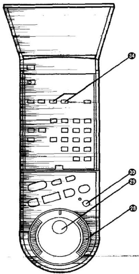
Additional Controls
17 MIC
Connect a microphone to this socket for recording. This socket has priority.
18 PHONES
For connecting stereo headphones.
19 PHONES LEVEL
For adjusting the volume level of connected stereo headphones.

20 PICTURE
For adjusting the sharpness of the picture. Sliding this control to the right makes the picture appear sharper, sliding it to the left makes it appear softer.
21 NOISE FILTER/EDIT
OFF: Set at this position for normal use of the VTR.
EDIT: Set at this position for editing operations (or dubbing the tape). The picture sharpness cannot be adjusted in this setting.
NOISE FILTER ON:
Use this setting when playing back tapes with inferior picture quality that could be caused, for example, by repeated dubbing.
- When playing back S-VHS recordings, the "NOISE FILTER ON" position will have no effect.
22 TBC (Time Base Corrector)
When the tape in the cassette is loose or damaged, or when the tape movement is unstable during recording or playback, the playback picture may shake from side to side and the picture may become distorted. In this case, activate the Time Base Corrector by setting the TBC Switch to ON, and the picture will become stable and the shaking will be minimized
- For normal use, set the TBC Switch to OFF.
- During playback of some pre-recorded tapes, the tape may shake vertically. In such a case, set the TBC Switch to OFF.
- This function only works during normal playback in the PAL format.

23 SEARCH SOUND
OFF: The sound is played back only during normal playback.
ON: The sound is also produced in all the special playback functions except still playback.
- There may be cases in which no audio is audible in the LP mode if connections between the VTR and TV are made with a DIN-DIN coaxial cable only.
24 Hi-Fi/NORMAL MIX
Sound is recorded on both the Hi-Fi and normal sound tracks.
OFF: Normally set at this position to reproduce the better sound available from the Hi-Fi track.
ON: Both sound tracks are played back mixed together. Use this setting when playing back a cassette tape which has been insert edited or audio dubbed.
25 INPUT SELECT FRONT
When Recording via the sockets on the front panel, select A4 by INPUT SELECT on the remote controller and set this switch.
S-VIDEO: Recording via S-VIDEO IN and AUDIO IN (AV4).
LINE: Recording via VIDEO IN and AUDIO IN (AV4).
26 TAPE SELECT
Set this switch according to the cassette tape being used so that the remaining tape time is indicated correctly.
\~E195: For E30, -60, -80, -120, -180 and -195 tapes.
E240: For E240 tape.
E260: For E260 tape
27 NICAM/MONO
NICAM: Normally set at this position.
MONO: Only set at this position to record the normal sound during a NICAM broadcast or if the stereo sound is distorted due to inferior reception conditions.
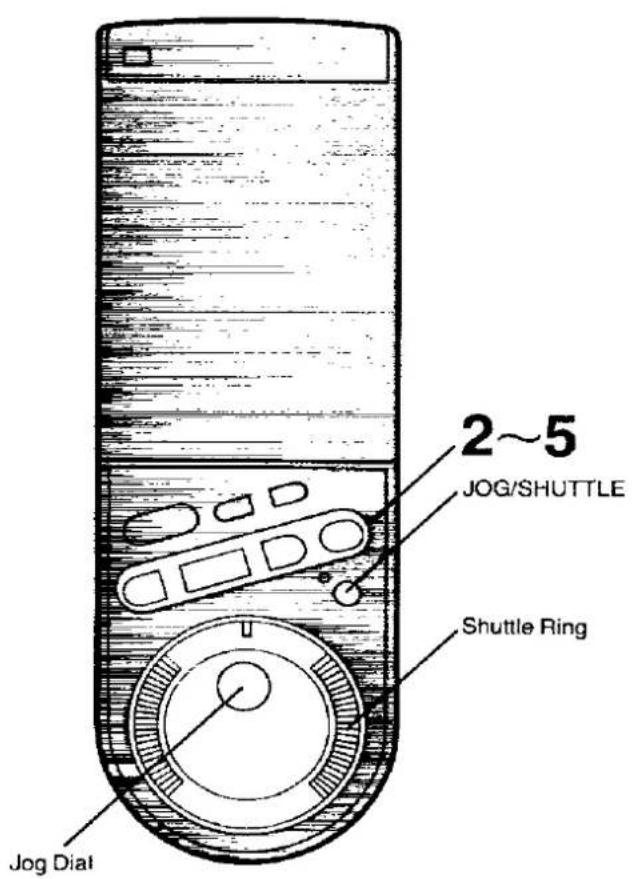
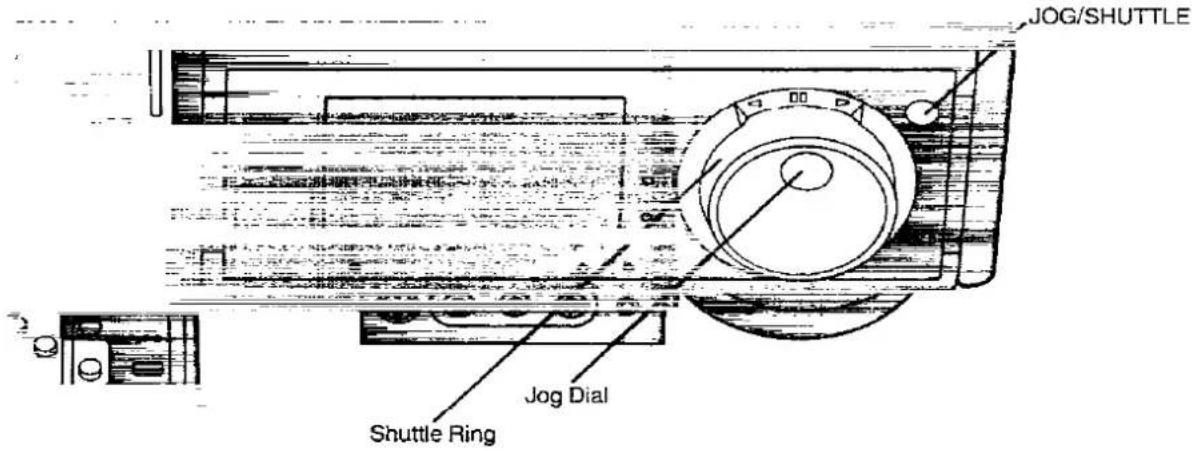
28 Shuttle Ring
With the Shuttle Ring, the playback speed can be adjusted step by step in both forward and reverse directions.
29 Jog Dial
The Jog Dial makes it easy to locate any desired frame with utmost precision.
30 Jog/Shuttle
Press this button to switch over to the jog and the shuttle operation.
31 CLOCK
Press this button to initiate date and time settings. After the time has been entered correctly, this button is pressed again to memorize the setting.
32 PROG/CHECK
This button is used to select the programme number for timer recording. Number "1, 2, 3... or 8" is lit. The button is also used to display details of a preset timer recording.
33 PRESET/NORMAL
Press this button to initiate TV station settings for the tuner.

34 TRACKING/V-LOCK
For manual tracking adjustment
The + and - buttons are used to adjust the tracking when, for example, noise bars on the picture are better removed manually than by the automatic digital tracking control. After making a manual adjustment, press both buttons together to return to automatic digital tracking control.
Manual tracking adjustment is sometimes necessary to reproduce good Hi-Fi sound and picture quality when playing back tapes that have been recorded on another VTR.
For slow tracking adjustment
When noise bars appear during Still, Still Advance or Slow playback, switch over to slow playback and adjust with the "+" or "-" Button to reduce the noise bars.
For vertical locking adjustment
Use the - and - buttons to minimize any vertical jitter during still-picture playback.
For setting the clock and timer recording (Remote controller: No function)
These buttons are also used for selecting the different time units when setting the clock to the present time, and for setting the data necessary for timer recording.
35 NEXT
Press this button to memorize preset data and to change to the next variable when setting the clock or timer. At each push, the flashing indication on the date display changes in the order YEAR, MONTH, DATE, HOUR, MINUTE.
36 TIMER REC
This button used to set the VTR for timer recording. When set for timer recording, is lit, and the VTR will turn itself on automatically to begin recording at the preset time.
The VTR can only be operated manually when the timer recording function is off. Timer recording can be set whether the function is on or off, but recording will only be performed when the function is on. If the timer recording function is on, but no video cassette is inserted or no timer recording has been programmed, the ☐ will flash to warn that timer recording cannot be performed
37 STORE
Press this button to memorize the tuner setting for a TV station.
38 AUDIO DUB
Press this button to set up the VTR for audio dubbing The Audio Dubbing Indicator lights up.
39 INSERT
Press this button to set up the VTR for insert editing. The Insert Editing Indicator lights up.
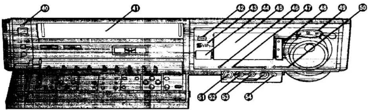
40 VTR Indicator
41 Cassette Compartment
42 PUSH-OPEN
Push this button to open the control panel.
48 S-VHS Indicator
44 Infra-red Remote Control Receiver Window Receives the signals from the remote controller.
45 Multi-Function Display

① Audio Level Meter
② Timer Programme Number
③ Channel Display
④ Cassette-in Indicator
⑤ Tape Running Display
⑥ Timer Recording Indicator
⑦ Recording Indicator
⑧ OTR Indicator
⑨ Position Indicator
⑩ Date Display
⑪ Write Indicator
⑫ Remaining Tape Time Indicator
⑬ Audio Output Mode Indicators
⑭ Tape Speed Indicator
⑮ Counter Mode Indicator
⑯ Repeat Indicator
⑰ Search Indicator
⑱ Clock/Counter Display
Clock Mode: Indicates present time.
Counter Mode: The numbers on the tape counter only change for recorded portions.
The circulating illumination is displayed in the last 2 digits during non-recorded portions.
46 TBC Indicator
47 Audio Dubbing Indicator
④3 Indicator Lamps for M1, M2 and Stereo Reception When receiving a TV programme, automatically indicates when a TV programme is broadcast with the NICAM sound system.
49 Jog/shuttle Indicator
This indicator lights up when the Jog/Shuttle Button is pressed.
50 Insert Editing Indicator
51 S-VIDEO IN (AV4)
For connecting the S-video cable of a video camera or a second video recorder.
52 VIDEO IN (AV4)
For connecting the video cable of a video camera or a second video recorder.
53 AUDIO IN (AV4)
For connecting the audio cable(s) of a video camera, a hi-fi stereo system or a second video recorder.
54 SYNC. EDIT
Connecting to a Movie Camera equipped with Synchro Edit Function.
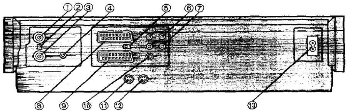
① RF OUT
Use this to connect to the aerial terminal on a TV set.
② LEVEL
Used to adjust the UHF aerial signal strength. It is normally set to the HIGH position. However, if diagonal pattern or stripes appear on picture try setting to LOW position.
③ RF IN
Use this to connect an external aerial.
④ CH ADJ.
Tape playback picture, etc. transmit with channel 36 but if it is occupied by local station. It can be adjusted ±4 ch.
⑤ NORMAL/S-VIDEO OUT/TEST SIGNAL
NORMAL: Normally set to this position.
S-VIDEO OUT: (AV1 Only)
Set to this position when connecting the VTR to a TV set equipped with 21-pin
Connector with pins for separate Y/C signal input.
TEST SIGNAL:
Set to this position when tuning the TV into the VTR.
The test signal is transmitted on channel 36.
⑥ AUDIO IN (AV3)
Use these to connect the sound to a stereo audio system.
⑦ AUDIO OUT
Use these to connect the sound to a stereo audio system.
⑧⑨ AV1/AV2
The 21 pin scart terminal carries input and output signals for both picture and sound. TV sets equipped with a similar socket can be connected here.
This is also called: Scart, Euro Connector Peritel, Euro AV

NORMAL (AV1 and AV2)
1 AUDIO OUTPUT CHANNEL 2 (R)
2 AUDIO INPUT CHANNEL 2 (R)
3 AUDIO OUTPUT CHANNEL 1 (L)
4 AUDIO GROUND
5 BLUE GROUND
6 AUDIO INPUT CHANNEL 1 (L)
7 BLUE
8 SWITCHING VOLTAGE
9 GREEN GROUND
10 No connection
11 GREEN
12 No connection
13 RED GROUND
14 BLANKING GROUND
15 RED
16 BLANKING
17 VIDEO OUTPUT GROUND
18 VIDEO INPUT GROUND
19 VIDEO OUTPUT
20 VIDEO INPUT
21 GROUND
⑩ EDIT
S-VIDEO (AV1 Only)
1 AUDIO OUTPUT CHANNEL 2 (R)
2 AUDIO INPUT CHANNEL 2 (R)
3 AUDIO OUTPUT CHANNEL 1 (L)
4 AUDIO GROUND
5 No connection
6 AUDIO INPUT CHANNEL 1 (L)
7 No connection
8 SWITCHING VOLTAGE
9 No connection
10 No connection
11 No connection
12 No connection
13 No connection
14 No connection
15 C OUT (CHROMA)
16 No connection
17 VIDEO OUTPUT GROUND
18 No connection
19 Y OUT (LUMINANCE)
20 VIDEO INPUT
21 GROUND
⑪ S-VIDEO IN (AV3)
By connecting the optional Editing Controller (VW-EC300E/VW-EC310E) to this socket, such editing functions as Assemble Editing, Insert Editing and Audio Dubbing can be performed more quickly and efficiently between two VTRs or between a VTR and a camera recorder.
For connecting to another VTR or to a signal source that has a S-Video Output Socket.
⑫ S-VIDEO OUT
For connecting to another VTR or to a TV set that has a S-Video Input Socket.
⑬ ACIN-

Infra-Red Remote Controller
1 INPUT SELECT
Press this button to select the "A1"—"A4" external recording source.
A1 provides signals that are input via the AV1 socket. A2 provides signals that are input via the AV2 socket. A3 provides signals that are input via the S-VIDEO IN and AUDIO IN sockets (AV3).
A4 provides signals that are input via the sockets on the front panel.
2 TAPE REMAIN
Press this button to have the approximate remaining tape time displayed.
"REMAIN" is lit while the remaining tape time is displayed.
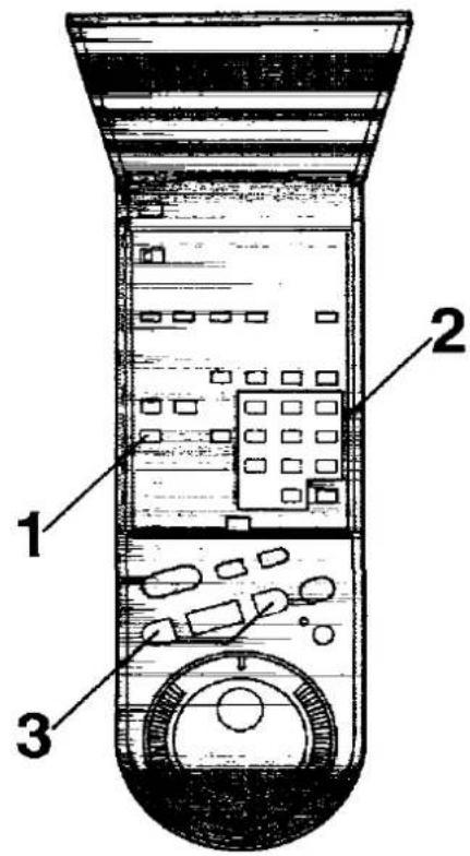
3 CLOCK/COUNTER
This button is used to switch between the display of the clock and the tape counter.
4 TIME SEARCH
For the time search function.
5 RESET
To reset the tape counter (elapsed time) to "0:00.00". ●The Tape Counter is automatically reset to "0:00.00" when the video cassette is inserted.
6 Programme Position Selector Buttons
- for selecting the programme positions
• for the Time Search function
• for programming of timer recording
7 INDEX
For the index search function.
8 REPEAT
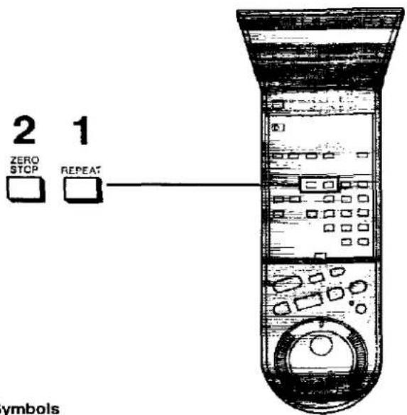
For the Repeat Playback function.
9 MONITOR
Keep this button depressed during playback to watch TV broadcast.
- When the VTR is connected to the TV set via 21 pin scart cable, this function does not work.
10 ZERO STOP
For the ZERO STOP function.
Digital Scanner

1 TRANSMIT
Press this button to transmit to the VTR data that has been set by bar codes.
2 Bar Code Reading Section
After the Bar Code Reader is turned on, the tip lights in red.
3 Digital Scanner On/Off Switch
To turn the Bar Code Reader on and off.
4 Bar Code Reader Display
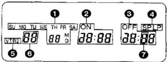
① Date Display
⑤ Remote Controi Mode Indicator
② Start Time Display
6 Channel Display
3 End Time Display
⑦ Check Indicator
4 Tape Speed Indicator
5 Infra-red Transmitter
The programming data are transmitted from here to the VTR.
Power source for the remote controller (digital scanner)
The Remote Controller is powered by 3 "UM3" or "R6" (Digital Scanner: 4 "UM4" or "R03") size batteries. The life of the batteries is about one year, although this depends on the frequency of use.
Precautions for battery replacement
- Load the new batteries with their polarity (+ and -) aligned correctly.
- Do not apply heat to the batteries, or an internal short-circuit may occur.
- If you do not intend to use the remote controller for a long period of time, remove the batteries and store them in a cool and dry place.
- Remove spent batteries immediately and dispose of them.
- Do not use an old and a new battery together, and never use an alkaline battery with a manganese battery
Loading the batteries
1 Remove the battery compartment lid.

natural_image
Line drawings of two electronic devices with buttons and connectors (no text or symbols)2 Place the batteries in the battery compartment according to the polarity indicated inside the battery compartment.

natural_image
Technical line drawing of a remote control device and its internal components (no text or symbols)3 Replace the lid.

natural_image
Line drawing of two electronic devices with no visible text or symbols
Operations
Display Symbols
1


Inserting a Video Cassette (Auto Operation)
Insert the video cassette as shown.
The VTR will be turned on automatically and the cassette will be automatically drawn into the VTR.
2

Removing a Video Cassette Press EJECT.
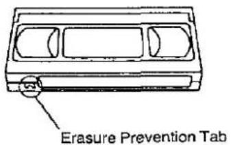
To prevent accidental erasure

Break off the tab with a screwdriver.
To record again

Cover the hole with adhesive tape.
Notes:
- When a video cassette with broken out erasure prevention tab (for example a pre-recorded tape) is inserted. playback will start immediately.
- Use VHS and S-VHS video cassette tapes only.
Basic Operations
Playback
The playback controls allow you to view at normal speed, to search for a specific scene with the tape moving faster than normal, to freeze into a still picture, to advance this still picture frame by frame, and to view in slow-motion.
On-the-spot Recording
You can record a TV programme without turning on the TV, and you can record one TV programme while viewing another.
One-Touch Timer Recording (OTR)
OTR allows you to quickly set up the VTR to record a single programme starting within the next 24 hours.
Playback


flowchart
graph TD
    A["Operations"] --> B["1"]
    B --> C["PLAY"]
    C --> D["3"]
    D --> E["4"]
    E --> F["5"]
    F --> G["PAUSE/ STILL"]
    style A fill:#f9f,stroke:#333
    style B fill:#ccf,stroke:#333
    style C fill:#cfc,stroke:#333
    style D fill:#fcc,stroke:#333
    style E fill:#cff,stroke:#333
    style F fill:#ffc,stroke:#333
    style G fill:#fcf,stroke:#333
Insert a recorded cassette tape.
- If it has already been inserted, press VTR to turn the unit on. Turn on the TV and select 21 pin scart terminal input or station number which has been tuned to channel 36 for VTR playback.
Start viewing the picture by pressing PLAY.
- When a tape is inserted with erasure prevention tab removed playback will start automatically.
To search for a specific scene while viewing the picture, press and hold down FF to search ahead.
For longer Cue playback, quickly press the button to start the Cue playback. To change back to normal playback, press PLAY.
To search for a specific scene while viewing the picture, press and hold down REW to search back.
For longer Review playback, quickly press the button to start the Review playback. To change back to normal playback, press PLAY.
To interrupt playback for a still picture, press PAUSE/STILL.
To continue the normal playback, press PLAY or this button again.
Jog/Shuttle
1 Press JOG/SHUTTLE, and the VTR switches to still mode.
2 Using the Shuttle Ring, select the desired playback speed in both the forward and reverse directions.
3 Using the Jog Dial, locate the desired picture precisely.
Notes:
- If Cue or Review playback continues for more than 10 minutes, the VTR will automatically switch over to the normal playback mode. If the Still and Slow playback continues for more than 5 minutes, the VTR will automatically switch over to the stop mode.
- In Cue and Review playback, noise bars and distortions can occur on the screen. However, this is not a malfunction.
- Audio reproduction of linear (conventionally recorded) tapes will be monaural when played back on the FM Hi-Fi video recorders.
- In "LP" mode only:
- During any playback mode other than normal playback, the picture may have some noise bars, the colour may be unstable, or a black and white picture may appear.
- When playing back a tape which was recorded on another VTR, it may be necessary to adjust the Tracking Control. In some cases the picture quality may still be inferior. This is due to limitation of format.
On-the-spot Recording


Operations
Display Symbols
1


2


3
RECORDING
SPLP


4

5
PAUSE/
STILL


6

HI-FI REC LEVEL

Insert a cassette tape with an intact erasure prevention tab.
- If it has already been inserted, press VTR to turn the unit on.
Select the required TV station on the VTR by pressing √ ∧.
Select the tape speed SP or L.P.
Start recording by pressing REC.
- When a video cassette with broken out tab is inserted, the "box" indication will flash, and an alarm sound will be produced to indicate that recording is not possible.
To interrupt recording, press PAUSE/ STILL, and press again to continue recording.
- If you leave the VTR in the pause mode for more than 5 minutes, the VTR will automatically switch over to the stop mode to protect the tape and the video heads.
To stop recording, press STOP.
Recording one TV programme while viewing another
- Use the on-the-spot recording operations.
- Select the TV programme on your TV set you wish to view at the present time.
Note:
When the connections are made as shown on page 9, it is not possible to watch programmes received via Satellite Receiver (connected to AV2) while recording a TV programme from the VTR's built-in tuner (or signals input via AV1, AV3, AV4).
Adjustment of the Hi-Fi Audio Recording Level
Setting the HI-FI REC LEVEL to the centre "5" position (click stop) assures satisfactory audio recording results in most cases. When using the VTR as a Hi-Fi audio recorder or when producing your own video tapes, it may be desirable to adjust the HI-FI REC LEVEL to some other position. (It is recommended to adjust so that peaks in the audio level reach about -4 dB.)
- The sound to be recorded on the "normal" audio track will be adjusted automatically.
One-Touch Timer Recording (OTR)
For example: OTR recording of a TV Station 1 from 20:02 to 20:30.

1


2


3

4

5

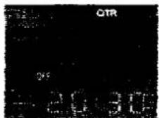

Insert a cassette tape with an intact erasure prevention tab.
- If it has already been inserted, press VTR to turn the unit on.
Select the required TV station on the VTR by pressing ▼ ▲.
Select the tape speed SP or LP.
Set the starting time by pressing OTR ON.
- When a video cassette with broken out tab is inserted, the "..." indication will flash, and an alarm sound will be produced to indicate that recording is not possible.
- If you want the recording to start immediately, omit this step.
Set the ending time by pressing OTR OFF.
After 4 seconds, the display will automatically change back to the starting time indication.
- The VTR will automatically switch off, when the OTR is completed. To turn the VTR on again, press VTR.
Notes:
• To cancel an OTR setting, press VTR.
- It is possible to change the OTR starting time or the ending time before the recording starts.
- It is possible to change the OTR ending time during recording.
- Make sure that the OTR Function (One-Touch Timer Recording) does not overlap a programmed timer recording. An OTR always takes precedence over a timer recording.
To confirm the OTR ending time before the recording starts
Press PROG/CHECK once.
When this button is pressed twice, the display will change to the clock indication mode.
To confirm the present time during recording Press PROG/CHECK.
Advanced Operations
Timer Recording
Up to 8 programmes can be recorded up to one month in advance by setting the timer.
This can also handle recording of daily and weekly programmes.
The daily recording can be set according to 3 patterns:
Monday to Friday
Monday to Saturday
Sunday to Saturday
Timer recording can be performed with Digital Scanner using the Bar Code Programming Sheet (see page 50).
Search Function
VHS Index Search System
It is very easy to find the beginning of each recording, because a special index signal is recorded at the start of each recorded segment on the tape.
Up to 20 index signals can be searched for in both directions.
Time Search
This makes it possible to advance or reverse the tape by a certain period of playback time.
Editing
Copy Editing
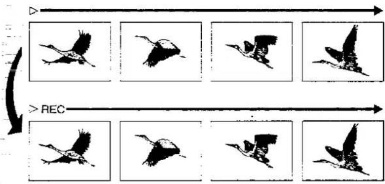
One recorded tape can be copied on to another blank tape.
Assembly Editing
This enables you to record a new segment immediately after a previously recorded segment without any noise between.
Synchronized Editing
It is possible to synchronize the playback start and stop of the Movie Camera with the recording start and stop of this VTR.
Insert Editing
This editing method allows a new recorded segment to be inserted into an existing recording to replace an existing segment of the same length.
Audio Dubbing
This enables you to record new sound on a previously recorded tape
Other Functions
NICAM
The NICAM system is a ground-based TV transmission system for digital stereo sound. This VTR is equipped with a NICAM decoder to receive NICAM broadcasts.
Automatic features
The VTR incorporates a number of automatic features for easy operation.
NTSC Playback
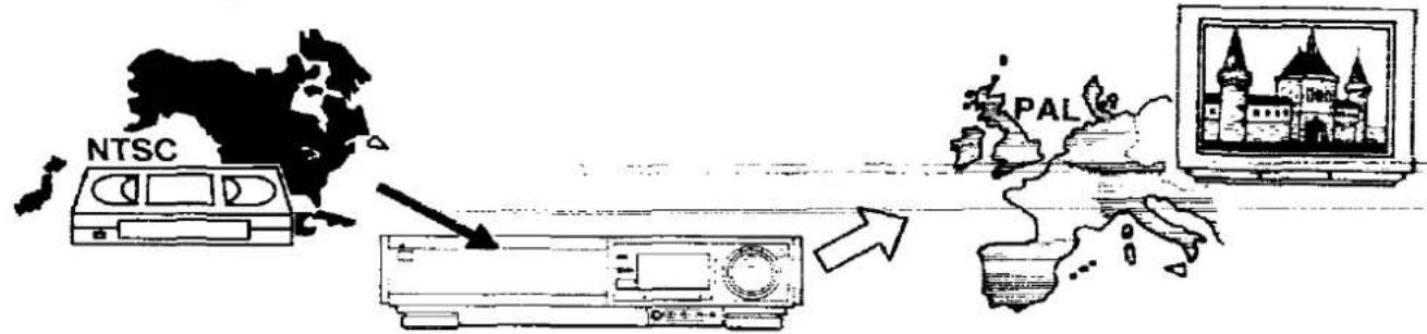
Cassette tapes recorded with the NTSC system can be played back on this VTR through a PAL system TV, allowing you to enjoy movies direct from the USA, Japan or other countries using the NTSC system.
Bar Code Operation
A bar code digital scanner enables you to set the programme recording timer simply by reading appropriate bar codes.
Timer Recording
For Example:
Programming a timer recording for a TV programme that will be broadcast on Wednesday, October 27, from 20:02 to 21:30, on programme position (channel) 1, on timer programme number 1. (Present date=October 10, 1999)

| Operations | Display Symbols | |||
| 1 |  |  | Insert a cassette tape with an intact erasure prevention tab.●If it has already inserted, press VTR to turn the unit on. | |
| 2 |  |  | Select the programme number by pressing PROG/CHECK. | |
 |  | Select the recording speed by pressing RECORDING SP/LP. | ||
| 4 |  |  | →NEXT | Select the TV station by pressing TRACKING/V-LOCK + or - and memorize by pressing NEXT. |
| 5 |  |  | →NEXT | Set the date by pressing TRACKING/V-LOCK + or - and memorize by pressing NEXT.●For daily recording, select one of the three different daily patterns by pressing TRACKING/V-LOCK + or -.●For weekly recording, select the day by pressing TRACKING/V-LOCK + or -. |
| 6 |  |  | NEXT | Set the starting time hour by pressing TRACKING/V-LOCK + or - and memorize by pressing NEXT. |

Operations
Display Symbols
7


8

9

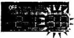
10

Set the starting time minute by pressing TRACKING/V-LOCK + or - and memorize by pressing NEXT.
Set the ending time hour by pressing TRACKING/V-LOCK + or - and memorize by pressing NEXT.
Set the ending time minute by pressing TRACKING/V-LOCK + or -.
• There is no need to press NEXT.
- Repeat steps 2 to 9 for the other programmes.
Activate timer recording by pressing TIMER REC.
- is displayed and the VTR is set in the standby mode so that it cannot be operated manually.
- If you want to operate the VTR manually, press TIMER REC.
To reactivate the timer press this button again.
Confirming the timer settings
Select the programme number to be checked by pressing PROG/CHECK.
The preset channel and start and ending times of the timer recording will be indicated for about 12 seconds.
Canceling the timer settings
- Release from the standby mode by pressing TIMER REC.
- Select the programme number to be canceled by pressing PROG/CHECK.
- Press TRACKING/V-LOCK + and - simultaneously for more than 3 seconds.
Note:
If a timer recording is not performed to the end (not enough tape or cancelled by the user), the programmed timer recording data will be cancelled from the memory at 4 a.m. two days later.
However, if the Timer Record Function is activated or an OTR is programmed or performed at that time, the programmed timer recording data will be cancelled at 4 a.m. the next day.
Search Function
Recording of Index Signals
While recording an index signal, the indication "WRITE" lights up for a few seconds. Index signals will be recorded automatically at the start of recording. It is also possible to record an index signal by pressing REC during recording, to mark your own reference point.
VHS Index Search System
Preparation
Set the VTR in the normal playback or stop mode.
For example:
Searching for the 2nd recorded segment in forward direction.

flowchart
graph LR
    A["Historical Image 2"] --> B["Historical Image 1"]
    B --> C["Historical Image 1"]
    C --> D["Historical Image 2"]

Operations

Display Symbols

Select the 2nd recorded segment by pressing INDEX ▶▶ twice.
- For the reverse direction, press INDEX ◀◀.
●After finding the specific recorded segment, playback starts.
Notes:
- The Search function can only count the addresses correctly, if the index signals are spaced at least 3 minutes in the SP mode and 5 minutes in the LP mode.
- If there are unrecorded parts on the tape, or if recordings have repeatedly been made on the same tape portion, the Search function may not work correctly
Time Search
It is easy to search forwards or backwards along the tape by a specific amount of playback time to locate a scene or skip part of programme.
Preparation
Insert a recorded cassette tape.
Set VTR to the stop mode.
For example:
Searching for the recording 5 min. and 43 sec. from this point.
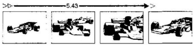
Operations
Display Symbols



Enter the 5 min. and 43 sec. by pressing the number buttons.


Start searching by pressing FF or REW.
The playback starts after rewinding or fast forwarding to the tape position of the designated time.
Copy Editing
This function is used to make duplicate.
Preparation
Connect a Movie Camera or another VTR to this VTR as shown.
Set NOISE FILTER/EDIT to EDIT.
Insert the recorded tape in the already connected video source, and a blank tape into this VTR and select A1\~A4 by pressing INPUT SELECT.
A1: Recording via AV1 Socket.
A2: Recording via AV2 Socket.
A3: Recording via S-VIDEO IN and AUDIO IN Sockets (AV3).
A4: Recording via Sockets on front panel.
Set INPUT SELECT FRONT on the VTR.
S-VIDEO: Recording via S-VIDEO IN and AUDIO IN Sockets (AV4).
LINE: Recording via VIDEO IN and AUDIO IN Sockets (AV4).

Operations
Display Symbols
1
PLAY


Play back the recorded tape on the Video source.
2
REC


Copy the tape by pressing REC on this VTR.
Note:
- Set NOISE FILTER/EDIT to OFF for ordinary use of the VTR.
Assembly Editing
It can be used to make up an Edited tape from several other recordings or video sources.
A new scene can be added to the end of a previous one, providing a clean edit without noise.
Preparation
Insert a recorded cassette tape with an intact erasure prevention tab, and select the video source required by pressing INPUT SELECT to set A1\~A4.
Set NOISE FILTER/EDIT to EDIT.

flowchart
graph TD
    A["1"] --> B["2"]
    B --> C["3"]
    C --> D["4"]
    D --> E["5"]
    E --> F["6"]
    F --> G["7"]
    G --> H["8"]
    H --> I["9"]
    I --> J["10"]
    J --> K["11"]
    K --> L["12"]
    L --> M["13"]
    M --> N["14"]
    N --> O["15"]
    O --> P["16"]
    P --> Q["17"]
    Q --> R["18"]
    R --> S["19"]
    S --> T["20"]
    T --> U["21"]
    U --> V["22"]
    V --> W["23"]
    W --> X["24"]
    X --> Y["25"]
    Y --> Z["26"]
    Z --> AA["27"]
    AA --> AB["28"]
    AB --> AC["29"]
    AC --> AD["30"]
Operations 4 Display Symbols

natural_image
Black curved arrow pointing upward and right (no text or symbols)


Note:
The new sound will be recorded on both the normal and Hi-Fi sound tracks. only monaural sound recording is possible on the normal sound tracks.
Synchronized Editing
It is possible to synchronize the playback start and stop of the Movie Camera with the recording start and stop of this VTR.

Preparation
Connect a Movie Camera to this VTR with Synchro Connection Cord (optional).
Insert a recorded cassette tape with an intact erasure prevention tab, and select the video source required by pressing INPUT SELECT to set A1\~A4. Set NOISE FILTER/EDIT to EDIT.
| Operations | Display Symbols | ||
| 1 | REC | PAUSE/ STILL | |
| 2 | Put the Movie Camera in the still playback mode at the point where you want to start editing. |
| 3 | PAUSE/ STILL | Press PAUSE/ STILL on the VTR.●The Movie Camera changes over to the playback mode and the dubbing will start automatically. | |
| II |
Synchronized Editing between the VTRs
When editing from another VTR equipped with Synchro Edit Socket, synchronized start and stop of both VTRs can be activated from this VTR.
The operation is the same as described for synchronized editing from a Movie Camera.
Note:
Synchronized editing may only function correctly when used with another Panasonic VTR or Movie Camera.
Insert Editing

flowchart
graph TD
    A["1: Insert"] --> B["2: Edit 0:00.00"]
    B --> C["3: Insert"]
    C --> D["4: > INSERT"]
Operations
| 1 | JOG/SHUTTLE | Press JOG/SHUTTLE. | |
| 2 | RESET | Use the Shuttle Ring and the Jog Dial to search for the point where you want the editing to end (out point), and set the counter to 0:00.00 by pressing RESET. | |
| 3 | INSERT | Use the Shuttle Ring and the Jog Dial to search for the point where you want the editing to start (in point), and press INSERT. (The insert Editing Indicator lights up.) If you want to replace the sound on the "normal" audio track, too, press AUDIO DUB. (The Audio Dubbing indicator lights up.) | |
| 4 | PAUSE/ STILL | Start insert editing by pressing PAUSE/ STILL, and the inserted new recording will stop in the still playback mode when the counter reaches 0:00.00. |
Note:
The new sound will be recorded on the Hi-Fi sound track. If AUDIO DUB selected, the new sound will also be recorded on the normal sound track.
Only monaural sound recording is possible on the normal sound tracks.
Audio Dubbing
It is used to add the back ground music etc.
Preparation
Insert a recorded cassette with an intact erasure prevention tab, and select the audio source required by pressing INPUT SELECT to set A1\~A4.

flowchart
graph TD
    A["1"] --> B["2"]
    B --> C["3: A. DUB"]
    C --> D["4 > A. DUB"]
    D --> E["Downward arrow"]
    E --> F["Final 1: DUBs with bird silhouettes"]
    F --> G["Next Step"]
| Operations | Display Symbols | ||
| 1 |  |  | Search for the starting point at which you want to record new sound by pressing PLAY. |
| 2 | [E/  |  | At the beginning of the point press PAUSE/ STILL. |
| 3 | [XUB] |  | Set for audio dubbing by pressing AUDIO DUB.(The Audio Dubbing indicator lights up.) |
| 4 | [E/  |  | Start recording the new sound by pressing PAUSE/ STILL.Stop recording by pressing STOP. |
Note:
The new sound will be recorded on the normal sound track of the tape, and the original sound will remain on the HiFi sound track. Only monaural sound recording is possible on the normal sound track.
To hear the new sound, select the normal sound track by pressing AUDIO OUT.
To hear the new sound and original sound mixed together, set HI-FI/NORMAL MIX to ON.
The NICAM Broadcast System

NICAM is a 2 Channel sound broadcast system to provide either a high quality stereo sound track or 2 independent MONO sound tracks, M1 and M2.
NICAM programmes are always accompanied by standard sound broadcasts and you can select the desired sound with NICAM/MONO (when recording) or with AUDIO OUT (when playback).
The NICAM digital stereo sound can only be recorded on the Hi-Fi audio track.
When a stereo, dual-soundtrack or mono NICAM programme is being received, the indicators are lit to inform you of the type of broadcast.
Reception of a NICAM Stereo Broadcast
When the STEREO indicator is lit, set NICAM/MONO to NICAM to be able to record on the Hi-Fi sound track in stereo.
The scart lead must also be connected to a stereo TV in order to hear the NICAM sound in stereo.
Reception of a NICAM Dual-Sound Broadcast
When the M1 and M2 indicators are lit, set NICAM/MONO to NICAM if you want to record both channels on the Hi-Fi sound track. M1 is the left-hand channel and M2 is the right-hand channel.
Reception of a NICAM Monaural Broadcast
When a NICAM monaural broadcast is being received, only the M1 indicator is lit. To hear such a signal on both channels and to record it on both channels of the Hi-Fi track, set NICAM/MONO to NICAM.
- To record the regular sound (ordinary normal sound) on the FM audio tracks when a NICAM programme is received, set NICAM/MONO to MONO.
Important Note for the NICAM System
When this VTR tuner is switched on, it will automatically switch to a NICAM broadcast. if NICAM is being transmitted. During test transmissions, it is possible that the sound received doesn't correspond to the picture being viewed. In order to receive a synchronized sound and picture, select monaural sound with either AUDIO OUT or with NICAM/MONO. This will only apply until NICAM transmissions are fully operational.
At this time the NICAM signal is transmitted on stereo channels only, since the M1 and M2 formats are not yet available. Even if the soundtrack is in MONO the stereo indicator will remain illuminated.
Automatic Features
Automatic playback control
Display Symbols
Operations
| 1 | R | To repeat playback from the beginning of tape to the end of the recorded segment, press REPEAT. | |
| 2 | ZERO STOP | To stop at the counter position 0:00.00 after rewinding or fast-forwarding, press ZERO STOP during stop mode. |
Automatic switching on
When a cassette is inserted, the VTR turns itself on automatically.
Automatic playback
When a cassette without an erasure prevention tab is inserted, the VTR starts playback automatically.
Automatic rewinding
When the tape reaches its end during recording (except for OTR and timer recording) or playback, it will automatically be rewound to the beginning.
Automatic switching off and ejection
When the VTR is switched off, an inserted cassette can be ejected simply by pressing EJECT. The VTR will eject the cassette and automatically turn itself off again.
Automatic head cleaning
This VTR automatically removes tape particles and dust from the video heads to ensure continuously superior picture quality. While the head cleaner is working, some mechanical noise can be heard from the VTR. This is not a malfunction.
NTSC Playback
flowchart
graph TD
    A["NTSC"] --> B["Regional Map"]
    B --> C["Digital Interface"]
    C --> D["PAL Island"]
    style A fill:#f9f,stroke:#333
    style B fill:#ccf,stroke:#333
    style C fill:#cfc,stroke:#333
    style D fill:#fcc,stroke:#333
Operations

Insert the NTSC cassette tape and play back by pressing PLAY.
Note:
- NTSC is the TV broadcasting system used in U.S.A., Japan, and some other countries. PAL is another TV broadcasting system used in U.K., Germany and many other parts of the world. This VTR will not replay or Record tapes on the SECAM broadcasting system.
NTSC 4.43 is a modified version of the PAL broadcasting system to allow most UK TV's to reproduce a colour picture when an NTSC tape is replayed on this VTR. However due to the system change, the picture may shrink, roll or not reproduce colour on some Televisions. - During playback of NTSC recordings, the Tape Counter does not function correctly.
Scanner Preparation
Set the Digital Scanner ON/OFF Switch to ON.
If no operation is performed for more than 25 seconds (4 minutes during setting of the clock time), the scanner will automatically switch over to the power-saving standby condition and the lamp will go off. (In this case, if bar codes have already been read but not yet transmitted to the VTR, the data will be cancelled.)
When the Digital Scanner On/Off Switch is set to ON but the lamp is not lit, set the switch to OFF and then ON again.

Reading the bar codes
1 Fit the digital scanner to the scanning adaptor.
2 Trace the bar code quickly in the direction of the arrow, ensuring that you trace it completely past the last bar. The "Beep" sound indicates that the bar code has been read completely.
When the Bar Codes Cannot be Read
Although the lamp in the tip of the Bar Code Reading Section lights up:
●No figures appear in the Display
- No beep sounds is heard:
The tip of the Bar Code Reading Section is probably clogged with dirt.

Cleaning
1 Remove the cap of the Bar Code Reading Section.
- Remove dirt and dust from the hole of the cap.
2 Gently wipe the tip of the lamp with a soft cloth.
●Reattach the cap and lock it.
Remote Control Modes
Adjust the remote control mode of the Digital Scanner to the same remote control mode (VTR 1 or VTR 2) as selected on the VTR itself.
When Remote Control Mode "VTR 2" is selected on the VTR
Trace the "VTR 2" bar code on the Programming Sheet. - "VTR 2" will appear in the Bar Code Reader Display. When the "VTR 1" bar code is traced, the "VTR 2" indication will disappear and the remote control mode is changed back to "VTR 1".
REMOTE MODE


Note: There is no indication on the display for "VTR 1".
Setting the Clock
Read in the following data successively by tracing bar codes 2 to 7 on the programming sheet.
For Example: Set the clock for Sunday, October 10, 1999, 20:15.
Preparation
Turn on the VTR.

flowchart
graph TD
    A["5 DATE"] --> B["6 START TIME"]
    B --> C["7 END TIME"]
    C --> D["2 OUTPUT"]
    D --> E["3 OUTPUT"]
    D --> F["4 OUTPUT"]
Display Symbols
Operations
1


To turn on the digital scanner, set the Digital Scanner On/Off Switch to ON.
2
SETTING OF THE CLOCK

Trace the bar code SETTING OF THE CLOCK.
3
YEAR

99
Trace the bar code for the year (YEAR).
| Operations | Display Symbols | ||
| 4 |  |  | Trace the bar code for the month (MONTH). |
| 5 | 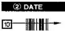 |  | Trace the bar code for the day of the month (DATE). |
| 6 | 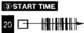 |  | Trace the bar code for the hour (START TIME).The repeated beep sound indicates correct bar code reading and readiness for transmitting the data to the VTR. |
| 7 | [MIN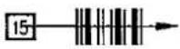 |  | Trace the bar code for the minute (MIN).The beep sound will be heard again. |
| 8 |  | To transmit the data to the VTR, point the digital scanner at the reception window on the VTR and press TRANSMIT.The transmitted data appears on the display, and a beep sound confirms proper reception. | |
| 9 |  | To turn off the digital scanner, set the Digital Scanner On/Off Switch to OFF again.If the digital scanner is left with no operation performed for more than 4 minutes, it will automatically switch over to the power-saving standby condition and the lamp in the reading tip goes out. In this case, bar codes that have already been read (but not yet transmitted to the VTR) will be cancelled. | |
Timer Recording
Setting Timer Recordings from Bar Codes
Successively scan the data for the programme channel, day, starting time and ending time by tracing bar codes 2 to 8 on the programming chart.
Preparation
Turn on the VTR.
For Example:
When programming a timer recording for a programme that will be broadcast on programme position 4 on the 3rd of the month, from 20:02 to 21:30.

flowchart
graph TD
    A["1 PROGRAMME"] --> B["2 DATE"]
    B --> C["3 START TIME"]
    C --> D["4 END TIME"]
    D --> E["5-7"]

    subgraph Program Start
        F1["□"] --> F2["□"] --> F3["□"] --> F4["□"] --> F5["□"] --> F6["□"] --> F7["□"] --> F8["□"] --> F9["□"] --> F10["□"] --> F11["□"] --> F12["□"] --> F13["□"] --> F14["□"] --> F15["□"] --> F16["□"] --> F17["□"] --> F18["□"] --> F19["□"] --> F20["□"] --> F21["□"] --> F22["□"] --> F23["□"] --> F24["□"] --> F25["□"] --> F26["□"] --> F27["□"] --> F28["□"] --> F29["□"] --> F30["□"] --> F31["□"] --> F32["□"] --> F33["□"] --> F34["□"] --> F35["□"] --> F36["□"] --> F37["□"] --> F38["□"] --> F39["□"] --> F40["□"] --> F41["□"] --> F42["□"] --> F43["□"] --> F44["□"] --> F45["□"] --> F46["□"] --> F47["□"] --> F48["□"] --> F49["□"] --> F50["□"] --> F51["□"] --> F52["□"] --> F53["□"] --> F54["□"] --> F55["□"] --> F56["□"] --> F57["□"] --> F58["□"] --> F59["□"] --> F60["□"] --> F61["□"] --> F62["□"] --> F63["□"] --> F64["□"] --> F65["□"] --> F66["□"] --> F67["□"] --> F68["□"] --> F69["□"] --> F70["□"] --> F71["□"] --> F72["□"] --> F73["□"] --> F74["□"] --> F75["□"] --> F76["□"] --> F77["□"] --> F78["□"] --> F79["□"] --> F80["□"] --> F81["□"] --> F82["□"] --> F83["□"] --> F84["□"] --> F85["□"] --> F86["□"] --> F87["□"] --> F88["□"] --> F89["□"] --> F90["□"] --> F91["□"] --> F92["□"] --> F93["□"] --> F94["□"] --> F95["□"] --> F96["□"] --> F97["□"] --> F98["□"] --> F99["□"] --> F100["□"]

    subgraph Program End
        G1["□"] --> G2["□"] --> G3["□"] --> G4["□"] --> G5["□"] --> G6["□"] --> G7["□"] --> G8["□"] --> G9["□"] --> G10["□"] --> G11["□"] --> G12["□"] --> G13["□"] --> G14["□"] --> G15["□"] --> G16["□"] --> G17["□"] --> G18["□"] --> G19["□"] --> G20["□"]
    end

    subgraph Program Start
        H1["□"] --> H2["□"] --> H3["□"] --> H4["□"] --> H5["□"] --> H6["□"] --> H7["□"] --> H8["□"] --> H9["□"] --> H10["□"] --> H11["□"] --> H12["□"] --> H13["□"] --> H14["□"] --> H15["□"] --> H16["□"] --> H17["□"] --> H18["□"] --> H19["□"]
    end

    subgraph Program End
        I1["○ □ □ □ □ □ □ □ □ □ □ □ □ □ □ □ □ □ □ □ □ □ □ □ □ □ □ □ □ □ □ □ □ □ □ □ □ □ □ □ □ □ □ □ □ □ □ □ □ □ □ ▢"]
        J1["○ □ □ □ □ □ □ □ □ □ □ □ □ □ □ □ □ □ □ □ □ □ □ □ □ □ □ □ □ □ □ □ □ □ □ □ □ □ □ □ □ □ □ □ □ □ □ □ □ □ "]
    end

    subgraph Program Start
        K1["○ □ □ □ □ □ □ □ □ □ □ □ □ □ □ □ □ □ □ □ □ □ □ □ □ □ □ □ □ □ □ □ □ □ □ □ "]
        L1["○ □ □ □ □ □ □ □ □ □ □ "]
        M1["○ □ □ □ "]
        N1["○ □ "]
        O1["○ "]
        P1["○ "]
        Q1["○ "]
        R1["○ "]
        S1["○ "]
        T1["○ "]
        U1["○ "]
        V1["○ "]
        W1["○ "]
        X1["○ "]
        Y1["○ "]
        Z1["○ "]
        AA1["○ "]
        AB1["○ "]
        AC1["○ "]
        AD1["○ "]
        AE1["○ "]
        AF1["○ "]
        AG1["○ "]
        AH1["○ "]
        AI1["○ "]
        AJ1["○ "]
        AK1["○ "]
        AL1["○ "]
        AM1["○ "]
        AN1["○ "]
        AO1["○ "]
        AP1["○ "]
        AQ1["○ "]
        AR1["○ "]
        AS1["○ "]
        AT1["○ "]
        AU1["○ "]
        AV1["○ "]
        AW1["○ "]
        AX1["○ "]
        AY1["○ "]
        AZ1["○ "]
        BA1["○ "]
        BB1["○ "]
        BC1["○ "]
        BD1["○ "]
        BE1["○ "]
        BF1["○ "]
        BG1["○ "]
        BH1["○ "]
        BI1["○ "]
        BJ1["○ "]
        BK1["○ "]
        BL1["○ "]
        BM1["○ "]
        BN1["○ "]
        BO1["○ "]
        BP1["○ "]
        BQ1["○ "]
    end

    subgraph Program Start
        C
        D
        E
        F
        G
        H
        I
        J
        K
        L
        M
        N
        O
        P
        Q
        R
        S
        T
        U
        V
        W
        X
        Y
        Z
    end

    subgraph Program End
        K
        L
        M
        N
        O
        P
        Q
        R
        S
        T
        U
        V
        W
        X
    end

    subgraph Program Start
        K
        L
        M
        N
        O
        P
        Q
        S
        T
        U
        V
        W
    end

    subgraph Program End
        K
    end

    subgraph Program Start
        K
    end

    subgraph Program End
        K
    end

    subgraph Program Start
        K
    end

    subgraph Program End
        K
    end

    subgraph Program Start
        K
    end

    subgraph Program End
        K
    end

    subgraph Program Start
        K
    end

    subgraph Program End
        K
    end

    subgraph Program Start
        K
    end
Operations
Display Symbols

| Operations | Display Symbols | ||
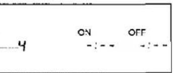
| 3 | 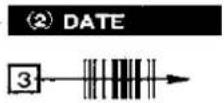 |  | Trace the bar code for DATE. |
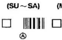 |  | Timer Recording Every Day at the Same TimeFor this timer setting, three day patterns can be selected:A Daily recording from Sunday to SaturdayB Daily recording from Monday to FridayC Daily recording from Monday to Saturday | |
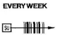 |  | Timer Recording at the Same Time on the Same Day Every WeekTrace the bar code for the day of the week in the EVERYWEEK column.For example, SU (Sunday). | |
| 4 |  |  | Trace the bar code for START TIME. |
| 5 | 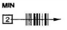 | 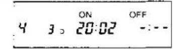 | Trace the bar code for MIN. |
| 6 | 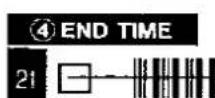 |  | Trace the bar code for END TIME.The repeated beep sound indicates readiness for data transmission to the VTR. |
| 7 |  | 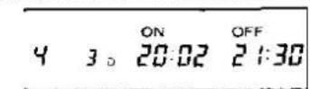 | Trace the bar code for MIN.The beep sound will be heard again. |
| 8 |  |  | Trace the bar code for RECORDING according to the desired tape speed.The beep sound will be heard again. |
| 9 |  | To transmit the data to the VTR, point at the reception window on the VTR and press TRANSMIT.The transmitted data appears on the display of the VTR and a beep sound confirms proper reception. | |
 | Programming a Series Timer RecordingsTrace the CANCEL bar code.Repeat the required steps 2 to 9 for each timer recording. | ||
| 10 |  | To turn off the digital scanner, set the Digital Scanner On/Off Switch to OFF again. | |
 |  | Turning the Timer on and offAfter programming a timer recording, the timer recording indicator "☐" lights up, and the VTR can no longer be used for normal recording and playback. To make it possible to use the VTR, trace the TIMER ON/OFF bar code and transmit to the VTR (the timer recording indicator "☐" will go out). To reactivate the timer again, trace the TIMER ON/OFF bar code again and transmit to the VTR (the "☐" indicator will light again). |
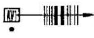 | 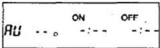 | Timer Recording from an External Signal SourceIf a timer recording is to be made from a signal source that is connected to the AV1 socket, the "AV" or "AV1" bar code in the PROGRAMME column must be traced for the programme.AV2. AV3 and AV4 cannot be selected with bar code. |
 | 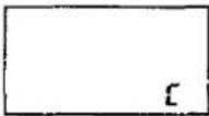 | Checking Timer Recording SettingsThe VTR must be turned on, or with the timer recording indicator "☐" lit.1. Trace the CHECK bar code.2. Transmit the data to the VTR.The programmed data will be displayed for about 12 seconds in the display panelTo check the settings for the next timer recording, press TRANSMIT. |
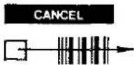 |  | Cancelling Timer Recording DataThe data for the timer recording must first be displayed on the panel.1. Trace the CHECK bar code.2. Transmit the data to the VTR.3. Trace the CANCEL bar code.4. Transmit the data to the VTR.The programmed timer recording will be cancelled and “-” dashes will appear on the display panel |
Helpful Hints
Before Requesting Service
Before requesting service, check the following points once again.
Precautions
Please read these cautions before you operate this VTR.
Specifications
Quick Reference
Before Requesting Service
Before requesting service, check the following points once again.
| VTR will not operate correctly | |||
| SYMPTOM | CAUSE | REMEDY | CHECKED |
| Multi-function display is not illuminated. | Mains lead not connected. | Reconnect mains lead to VTR and ensure switched on at mains plug. | |
| Fuse blown in plug. | Fuse cannot easily be checked. Replace fuse with known good one and check plug wiring. | ||
| Multi-function display is illuminated but VTR will not operate when VTR pressed. | VTR in timer mode. | Press TIMER REC to operate VTR manually. See page 35. | |
| Safety devices operating. | Disconnect mains lead and wait for 1 minute. Reconnect mains supply and check functions. | ||
| VTR will operate for a few seconds then power off. | Tape jammed in VTR. | If tape jammed in VTR do not attempt to remove, as this may cause damage. Consult your dealer for advice. | |
| Playback functions defective | |||
| SYMPTOM | CAUSE | REMEDY | CHECKED |
| Picture noisy or not in colour. | Not tracking correctly. | Although auto-tracking should ensure a good picture it may be necessary to manually adjust tracking on some tapes not recorded on this VTR. See page 18. | |
| TV set not tuned to VTR. | Operate test switch on VTR and check TV tuning. See page 11. | ||
| Tape recorded incorrectly. | Check aerial connected to VTR. See page 8. | ||
| Check that each programme position is tuned to the correct station. A snowy picture on one or more programmes may indicate VTR tuned to weak station or wrong transmitter.Re-tune if necessary.See page 12. | |||
| If timer record was used, confirm that a programme number had been selected that was correctly tuned. | |||
| Video heads clogged. | Condensation may have formed, or a faulty tape has been used. See Tape Care and Video Head Clogging. Do not operate VTR for 1 hour then insert a new tape (the original may be faulty) and playback for a few minutes. If fault does not clear consult your dealer for further advise. | ||
| Video head worn. | Carry out same procedure as for clogged video heads. If fault does not clear consult your dealer for advice. | ||
| Horizontal bars or lines run down picture or appear stationary. | Tape defective due to surface damage or wear. | Confirm other tape OK and replace defective tape.See separate section on tape care. | |
| Video heads may be worn or service required. | Consult your dealer for further advice. | ||
| VTR goes into auto rewind mode while playing tape. | Tape defective due to surface damage or wear causing end of tape detection to operate. | Replace defective tape. | |
| Black and white picture only (no colour) when using 21 pin connector socket. | NORMAL/S-VIDEO OUT TEST switch incorrected set. | Set to S-VIDEO OUT position when TV equipped with 21 pin connector with separate Y:C signal input. Set to normal at all other times. | |
| Record functions defective | |||
| SYMPTOM | CAUSE | REMEDY | CHECKED |
| Alarm sound is produced and "indication flashes when ever recording is attempted. | Erasure prevention tab on cassette is broken out. | Use tape with intact erasure prevention tab or cover tab hole with adhesive tape, if original recording is no longer required. | |
| Picture is recorded with noise or blank screen. | Aerial or aerial lead defective. | Check aerial connection to VTR. See page 8. Check your normal TV picture. If no picture check your aerial. | |
| VTR is not correctly tuned. | Re-tune VTR. See page 12. Ensure input selector set to TV programme. | ||
| Input selector is not correctly set. | Press INPUT SELECT to select A1~A4 for external source or select TV programme. See page 21. | ||
| OTR will not function. | Clock is flashing 0:00. | Set clock to present time. (Note this is a 24 hour clock) See page 13. | |
| Timer recording cannot be performed. (With controls on VTR) | Clock or calendar incorrectly set. | Check clock and calendar. Set to present time. (Note this is a 24 hour clock). See page 13. | |
| Clock is flashing 0:00. | Set clock to present time. | ||
| Recording start or stop time setting incorrect. | Set recording start and stop time correctly. Try a short timer recording a few minutes ahead of the present time to confirm correct operation. See page 34. | ||
| VTR not set for timer recording. | After setting up timer recording set TIMER REC to on. | ||
| AV1~AV4 external recordings cannot be made. | Input Selector is not correctly set. | Select A1~A4. See page 38. | |
| External AV connections incorrect. | Check connections for external video and audio source are correct. See page 9 and 10. | ||
| Remote control functions defective | |||
| SYMPTOM | CAUSE | REMEDY | CHECKED |
| Remote controller does not operate correctly. | Remote controller transmitter beam not reaching VTR. | Ensure remote controller is being pointed at VTR and that transmitter beam is not obstructed. | |
| Distance is too far. | Use remote controller within 7 m of VTR. If range is reduced, replace batteries. | ||
| Batteries are exhausted. | Replace batteries by type UM3 or R6 type availabel from your dealer. Note caution when replacing on page 22. | ||
| Batteries incorrectly fitted (--) Reversed. | Fit batteries correctly as shown on page 22. | ||
| Remote controll mode of the VTR and the Remote Controller do not match. | Set the same remote controll mode. Either VTR 1 or VTR 2 shown on page 14. | ||
| Bar code reading not possible. | Digital scanner in power saving condition. | Turn off power switch on the digital scanner then turn on again. | |
| Bar code not traced correctly. | Practice tracing the bar code from left to right. Each bar code should take around half a second to trace. A beep indicates bar code is read correctly. | ||
| Bar code sensor cap blocked. | Remove sensor cap and clean as shown on page 47. | ||
| Bar code data cannot be transmitted to VTR. | VTR is turned off or is in timer mode. | Turn VTR on. | |
| VTR is operating. | Stop VTR. | ||
| Timer record memory is full. | Cancel timer recording to enter a new timer event or wait until one timer event has taken place. | ||
| Bar code reading was not followed by a repeated bleep. | Read bar code again. | ||
| Remote controll mode of the VTR and the digital scanner do not match. | Set the same remote controll mode. Either VTR 1 or VTR 2 shown on page 47. | ||
Precautions
Please read these cautions before you operate this VTR.
Cassette Compartment Door
When first unpacking the unit, you may notice that the cassette compartment door is partially open. This condition is due to the operation of a safety device designed to protect the unit from vibration during shipment; it is not a malfunction. When the AC mains lead is connected to a mains outlet, the door will return to its original position.
Avoid Sudden Changes in Temperature
If the VTR is suddenly moved from a cold place to a warm place, moisture may form on the tape and inside the VTR.
Humidity and Dust
Avoid places where there is high humidity or much dust, which may cause damage to internal parts.
Do Not Obstruct the Ventilation Holes
The Ventilation holes prevent abnormal increase in temperature. Do not block or cover these holes. Especially avoid covering the holes with soft materials such as cloth or paper.
Keep away from High Temperature
Keep the VTR away from extreme direct heat such as direct sunlight, heating radiators, or closed automobiles.
Keep Magnets away
Never bring a magnet or magnetized object near the VTR because it will adversely affect the performance of the VTR.
No Fingers or Other Objects Inside
Touching internal parts of this VTR is dangerous, and may cause serious damage to the VTR. Do not attempt to disassemble the VTR. There are no user serviceable parts inside.
Keep Water away
Keep the VTR away form flower vases. tubs, sinks, etc. CAUTION: If liquids are spilled into the VTR, serious damage could occur. If you spill any liquid into the VTR, consult qualified service personnel.
Lightning
To avoid damage by lightning, disconnect the aerial plug from the VTR.
Cleaning the VTR
Wipe the VTR with a clean, dry cloth. Never use cleaning fluid, or other chemicals. And do not use compressed air to remove dust.
Stacking
Place the VTR in a horizontal position, and do not place anything heavy on it.
Video Head Clogging
The video heads place picture signals on the tape during recording and read picture signals from the tape during playback and they are, therefore, of critical importance for the picture quality. To ensure that they can always provide optimum picture quality, this VTR is equipped with an Auto Head Cleaning Function that removes tape particles and dust from the video heads. However, if the VTR is used over extremely long periods of time, these heads may still become dirty and clogged. In such a case, the signals can no longer be recorded correctly, and the playback picture will be distorted accordingly. This is the case, for example, during the playback of a tape, the sound is reproduced normally, but no picture is seen, or the picture is greatly distorted. When such a symptom occurs consult your dealer for further advice.
Condensation may form in the VTR if:
• The VTR is in a room where the heater has just been turned on.
- The VTR is in a room with steam or high humidity.
• The VTR is brought from cold surroundings into a well-heated room.
- The VTR is suddenly brought from cool surroundings, such as an air-conditioned room or car, to a place which is hot and humid.
Note:
Do not operate the VTR for at least 1 hour if any of the above conditions occur.
This VTR does not incorporate a dew sensor.
Tape Care
Some do's and don'ts on tape care.
DO:
1) Use a good quality branded tape, such as Panasonic.
2) Keep in the Box supplied with your tape, or a video case, when not in use.
3) Try to use all the tape on a cassette by making recordings not only at the tape start but also in the middle and end sections. This will avoid many repeated recordings at the beginning of the tape resulting in premature wear.
4) Take care to insert a tape correctly in to the VTR to avoid damage.
DO NOT:
1) Expose the tape to high humidity or temperature.
2) Expose to liquid.
3) Expose to dust particles by storing directly on a carpet for example.
4) Use a damaged tape or attempt to repair.
5) Dismantle the cassette housing.
6) Attempt to lift the front cassette flap or touch the tape surface.
NV-FS200B...(U.K. model)
Information for Your Safety
Power Source:
220-240 V AC 50-60 Hz
Power Consumption:
Approx. 41 watts
Video Recording System:
2 rotary heads, helical scanning system
Video Heads:
4 heads
Tape Speed:
SP; 23.39 mm/sec.
LP; 11.7 mm/sec.
VHS/S-VHS tape
Tape Format:
SP; 240 min. with NV-E240
SP; 180 min. with NV-SE180
LP: 480 min. with NV-E240
LP: 360 min. with NV-SE180
FF/REW Time:
Approx. 2.5 min. with NV-E180
VIDEO
Television System:
CCIR; 625 lines, 50 fields, PAL colour signal
Modulation System:
Luminance; FM azimuth recording
Colour signal; converted subcarrier phase shift recording
Input Level:
VIDEO IN (AV4) (PHONO);
1.0 Vp-p.
75 ohm
AV1/AV2;
1.0 Vp-p.
75 ohm
S-VIDEO IN (AV3/AV4);
Y: 1.0 Vp-p.
75 ohm
(1) 本次股东大会的决议
C: 0.3 Vp-p.
75 ohm
Output Level:
AV1/AV2;
1.0 Vp-p,
75 ohm
S-VIDEO OUT:
Y: 1.0 Vp-p,
75 ohm
(二)本次股东大会的召集和召开程序
C: 0.3 Vp-p,
75 ohm
RF Modulated;
UHF channel 36 (±4),
75 ohm, terminated
AUDIO
Input Level:
AUDIO IN (AV3:AV4) (PHONO);
more than -10 dBV,
more than 47 kohm
AV1/AV2;
more than -6 dBV,
more than 10 kohm
MICROPHONE:
-70 dBV
Output Level:
AUDIO OUT (PHONO);
-8 dBV,
less than 1 kohm
AV1/AV2;
-6 dBV,
less than 1 kohm
HEADPHONES;
-30 dBV,
8ohm
Audio Track:
1 track (Normal-mono only), 2 channels (Hi-Fi sound-stereo)
Video Horizontal Resolution:
Colour: more than 240 lines (VHS/SP)
more than 400 lines (S-VHS/S-Video Socket)
Dynamic Range:
Audio; more than 90 dB (Hi-Fi audio track)
Audio Frequency Response:
20 Hz-20 kHz (Hi-Fi audio track)
Wow and Flutter:
0.005% Wrms:Hi-Fi
Operating Temperature:
5^ C-40^ C
Operating Humidity:
35%-80%
Weight:
8.0 kg
Dimensions:
460 (W)×109 (H)×403 (D) mm
Standard Accessories:
1 pc. DIN-DIN Coaxial Cable
1 pc. Remote Controller
3 pcs. "UM3" or "R6" size batteries
1 pc. Stereo type Phono Cable
1 pc. Digital Scanner (with Programming Sheet)
4 pcs. "UM4" or "R03" size batteries (for Digital Scanner)
1 pc. AC Mains Lead
1 pc. S-Video Cable
Weight and dimensions shown are approximate.
Specifications are subject to change without notice.
Quick Reference
Turn the VTR on
Insert Cassette tape
| Functions | Operations | Page No. | ||
| Playback |  | View the picture | PLAY | 26 |
| Searching |  | 26 | ||
| Still picture |  | 26 | ||
| Jog/Shuttle | 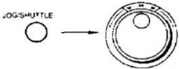 | 27 | ||
| Auto playback●Repeat |  | 45 | ||
| ●Zero Stop |  | 45 | ||
| Recording | [S7DG] | On-the-Spot | REC[SWDK] | 28 |
 | Programme Recording●One-Touch Timer Recording | [24DK] | 30 | |
| ●Timer Recording |  | 34 | ||
| Setting for TV programme, date (or day), starting time (hour, minutes), ending time (hour, minutes) | ||||
| Functions | Operations | Page No. | |
| Searching | Index Search |  | 36 |
| Time Search | 37 | ||
| Editing | Assemble | Edit Source | 40 |
| Insert |  | 42 | |
| Audio |  | 43 | |
- Dear Customer
- IMPORTANT
- WARNING
- FOR YOUR SAFETY
- ■ DO NOT REMOVE OUTER COVER.
- ■ AC MAINS LEAD CONNECTION
- HD (High Quality) Picture System
- Contents
- Setting up
- Basic Operations
- Advanced Operations
- Helpful Hints
- Unpacking
- How to use these operating instructions
- Connections
- Tuning the TV into your VTR
- Storing TV Broadcasts into your VTR
- Setting the Clock of the VTR
- Controls, Indicators and Connection Sockets
- The Video Cassette
- Additional Connections
- Connection to a TV Set with 21 Pin Scart Terminal
- Connection to a TV Set with S-Video Socket
- Note:
- Introduction
- Preparation
- 1,7 2\~6
- For Example:
- Basic Controls
- ① VTR (Video Cassette Recorder On/Off)
- REMOTE MODE (VTR 1/2)
- ③ HI-FI REC LEVEL
- S-VHS
- PLAY
- REC
- PAUSE/STILL
- RECORDING SP/LP
- 9
- OTR OFF (ONE-TOUCH TIMER RECORDING)
- ⑪ OTR ON (ONE-TOUCH TIMER RECORDING)
- AUDIO OUT
- REW (REWIND)
- STOP
- FF (FAST FORWARD)
- EJECT
- Additional Controls
- SEARCH SOUND
- Hi-Fi/NORMAL MIX
- INPUT SELECT FRONT
- TAPE SELECT
- NICAM/MONO
- Shuttle Ring
- Jog Dial
- Jog/Shuttle
- CLOCK
- PROG/CHECK
- PRESET/NORMAL
- TRACKING/V-LOCK
- NEXT
- TIMER REC
- STORE
- AUDIO DUB
- INSERT
- Infra-Red Remote Controller
- INPUT SELECT
- TAPE REMAIN
- CLOCK/COUNTER
- TIME SEARCH
- RESET
- Programme Position Selector Buttons
- INDEX
- REPEAT
- MONITOR
- ZERO STOP
- Digital Scanner
- TRANSMIT
- Bar Code Reading Section
- Digital Scanner On/Off Switch
- Bar Code Reader Display
- Infra-red Transmitter
- Power source for the remote controller (digital scanner)
- Precautions for battery replacement
- Loading the batteries
- Remove the battery compartment lid.
- Place the batteries in the battery compartment according to the polarity indicated inside the battery compartment.
- Replace the lid.
- Operations
- Display Symbols
- Inserting a Video Cassette (Auto Operation)
- Removing a Video Cassette Press EJECT.
- Notes:
- Playback
- On-the-spot Recording
- One-Touch Timer Recording (OTR)
- Insert a recorded cassette tape.
- Start viewing the picture by pressing PLAY.
- To search for a specific scene while viewing the picture, press and hold down FF to search ahead.
- To search for a specific scene while viewing the picture, press and hold down REW to search back.
- To interrupt playback for a still picture, press PAUSE/STILL.
- Jog/Shuttle
- - In "LP" mode only:
- HI-FI REC LEVEL
- Start recording by pressing REC.
- Recording one TV programme while viewing another
- Adjustment of the Hi-Fi Audio Recording Level
- Timer Recording
- Search Function
- Editing
- Other Functions
- Bar Code Operation
- Confirming the timer settings
- Recording of Index Signals
- VHS Index Search System
- Time Search
- Copy Editing
- Assembly Editing
- Synchronized Editing
- Synchronized Editing between the VTRs
- Audio Dubbing
- The NICAM Broadcast System
- Reception of a NICAM Stereo Broadcast
- Reception of a NICAM Dual-Sound Broadcast
- Reception of a NICAM Monaural Broadcast
- Important Note for the NICAM System
- Automatic Features
- Automatic switching on
- Automatic playback
- Automatic rewinding
- Automatic switching off and ejection
- Automatic head cleaning
- Scanner Preparation
- Reading the bar codes
- When the Bar Codes Cannot be Read
- Cleaning
- Remote Control Modes
- When Remote Control Mode "VTR 2" is selected on the VTR
- REMOTE MODE
- Setting the Clock
- Setting Timer Recordings from Bar Codes
- Before Requesting Service
- Precautions
- Specifications
- Quick Reference
- Cassette Compartment Door
- Avoid Sudden Changes in Temperature
- Humidity and Dust
- Do Not Obstruct the Ventilation Holes
- Keep away from High Temperature
- Keep Magnets away
- No Fingers or Other Objects Inside
- Keep Water away
- Lightning
- Cleaning the VTR
- Stacking
- Video Head Clogging
- Condensation may form in the VTR if:
- Tape Care
- DO:
- DO NOT:
Marque : PANASONIC
Modèle : NV-FS200B
Catégorie : Magnétoscope