
NV-SD220B - Magnétoscope PANASONIC - Notice d'utilisation et mode d'emploi gratuit
Retrouvez gratuitement la notice de l'appareil NV-SD220B PANASONIC au format PDF.


| Type de produit | Magnétoscope |
| Marque | Panasonic |
| Modèle | NV-SD220B |
| Format de cassette | VHS |
| Dimensions (L x H x P) | 430 x 85 x 240 mm |
| Poids | 3,5 kg |
| Alimentation | 220-240 V, 50 Hz |
| Fonctions principales | Enregistrement, lecture, avance rapide, rembobinage, programmation hebdomadaire, recherche automatique |
| Connectiques | Péritel, antenne HF entrée/sortie |
| Entretien et nettoyage | Utiliser une cassette nettoyante pour les têtes vidéo ; nettoyer le boîtier avec un chiffon doux et sec |
| Sécurité | Débrancher avant nettoyage ; ne pas ouvrir le capot : risque d'électrocution |
| Pièces détachées | Télécommande, câble péritel, câble d'alimentation, cassette nettoyante |
| Réparabilité (indice) | 6.0 / 10 |
| Consommation électrique | 20 W (approximatif) |
FOIRE AUX QUESTIONS - NV-SD220B PANASONIC
Questions des utilisateurs sur NV-SD220B PANASONIC
0 question sur cet appareil. Repondez a celles que vous connaissez ou posez la votre.
Poser une nouvelle question sur cet appareil
Téléchargez la notice de votre Magnétoscope au format PDF gratuitement ! Retrouvez votre notice NV-SD220B - PANASONIC et reprennez votre appareil électronique en main. Sur cette page sont publiés tous les documents nécessaires à l'utilisation de votre appareil NV-SD220B de la marque PANASONIC.
MODE D'EMPLOI NV-SD220B PANASONIC
Panasonic
Video Cassette Recorder
NV-SD220B
NV-SD220BL
Operating Instructions

natural_image
Illustration of a mannequin with a large envelope and scattered debris, no text or symbols presentVIDEO
VHS
PAL
SUPER DRIVE
MULTI-INTelligent CONTROL
16954
Before attempting to connect, operate or adjust this
product, please read these instructions completely
Dear Customer
May we take this opportunity to thank you for purchasing this Panasonic Video Cassette Recorder.
We would particularly advise that you carefully study the Operating Instructions before attempting to operate the unit and that you note the listed precautions.
Video Plus+ Programming System
Programming is now easier than ever: simply enter the PlusCode provided in the programme schedule column carried by newspapers and magazines.
- Video Plus+ and PlusCode are trademarks of Gemstar Development Corp. Video Plus+ system is manufactured under license from Gemstar Development Corporation.
Crystal View Control
Introducing Crystal View Control, and innovative new technology for high picture quality. This technology uses an microprocessor to intelligently control the relationship between the tape heads and circuitry, bringing out the maximum performance of each. The result is consistently optimum picture quality.
PDC (Programme Delivery Control) What is PDC?
PDC is a signal system transmitted by TV broadcasters to control the start and stop time of each programme. This signal is used by the VCR to control the start and stop time of programmed timer recordings.
PDC is particularly useful when the broadcaster changes the time for a programme from the published time, the VCR's timer recording start and stop time will be controlled by the broadcaster, e.g. when the programme is delayed or extended. Recording can also be interrupted by the broadcaster, e.g. news flash, and resumed when the programme restarts.
At present PDC transmission does not cover all areas and stations in the UK, please check with the broadcasters in your area for details.
natural_image
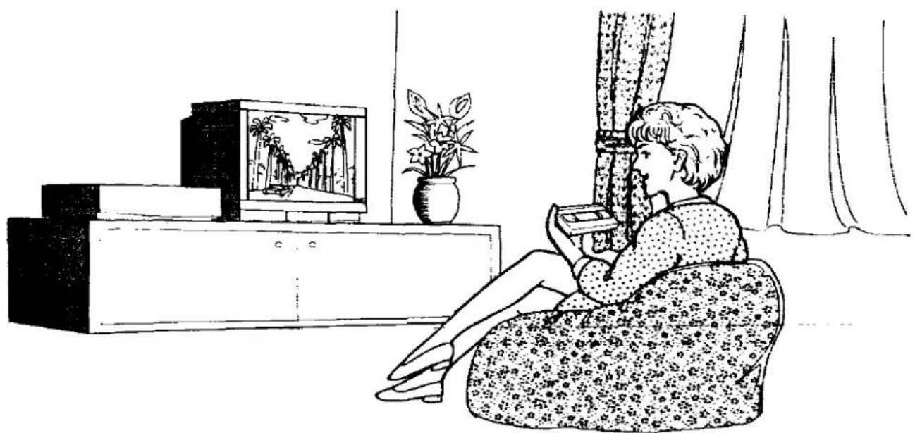
Illustration of a person sitting in a couch watching TV, with a potted plant and curtain in the background (no text or symbols)IMPORTANT
Your attention is drawn to the fact that the recording of pre-recorded tapes or discs or other published or broadcast material may infringe copyright laws.
WARNING
TO REDUCE THE RISK OF FIRE OR SHOCK HAZARD, DO NOT EXPOSE THIS EQUIPMENT TO RAIN OR MOISTURE.
As this equipment gets hot during use, operate it in well ventilated place; do not install this equipment in a confined space such as a book case or similar unit.
FOR YOUR SAFETY
■ DO NOT REMOVE OUTER COVER.
To prevent electric shock, do not remove cover. No user serviceable parts inside. Refer servicing to qualified service personnel.
Contents
Caution for AC Malns Lead 4
Unpacking 5
Infra-red Remote Controller 6
Controls and Connection Sockets 9
Setting Up
Connections 12
Tuning the TV to your VCR 14
Auto Setup 15
Basic Operations
Playback 18
Manual Recording 20
•One-Touch Recording (OTR) 22
Advanced Operations
Timer Recording 24
- Using On Screen Display 24
●Programming the Video Plus+ PlusCode 27
Editing 28
- Assembly Editing 28
Other Functions 29
Various Settings
Storing TV Broadcasts into your VCR 32
Settings Using On Screen Display 35
Setting the Clock of your VCR 37
Helpful Hins
Before Requesting Service 40
Precautions 43
Specifications Back Cover
For your safety please read the following text carefully
This appliance is supplied with a moulded three pin mains plug for your safety and convenience.
A 5 amp fuse is fitted in this plug.
Should the fuse need to be replaced please ensure that the replacement fuse has a rating of 5 amps and that it is approved by ASTA or BSI to BS 1362.
Check for the ASTA mark 📄 or the BSI mark 🌐 on the body of the fuse.
If the plug contains a removable fuse cover you must ensure that it is refitted when the fuse is replaced. If you lose the fuse cover the plug must not be used until a replacement cover is obtained.
A replacement fuse cover can be purchased from your local Panasonic Dealer.
IF THE FITTED MOULDED PLUG IS UNSUITABLE FOR THE SOCKET OUTLET IN YOUR HOME THEN THE FUSE SHOULD BE REMOVED AND THE PLUG CUT OFF AND DISPOSED OF SAFELY. THERE IS A DANGER OF SEVERE ELECTRICAL SHOCK IF THE CUT OFF PLUG IS INSERTED INTO ANY 13 AMP SOCKET.
If a new plug is to be fitted please observe the wiring code as shown below.
If in any doubt please consult a qualified electrician.
IMPORTANT
The wires in this mains lead are coloured in accordance with the following code:
Blue: Neutral
Brown: Live
As the colours of the wires in the mains lead of this appliance may not correspond with the coloured markings identifying the terminals in your plug, proceed as follows:
The wire which is coloured BLUE must be connected to the terminal in the plug which is marked with the letter N or coloured BLACK.
The wire which is coloured BROWN must be connected to the terminal in the plug which is marked with the letter L or coloured RED.
Under no circumstance should either of these wires be connected to the earth terminal of the three pin plug, marked with the letter E or the Earth Symbol ± .
How to replace the Fuse
- There are two types of the AC Mains Lead assembly: Ⓐ and Ⓑ as shown below.
1 Open the fuse compartment with a screwdriver.
2 Replace the fuse and fuse cover.


natural_image
Line drawing of a plug socket with wires inserted (no text or symbols)

natural_image
Technical line drawing of a mechanical component with two parts, no text or symbols presentCheck and identify the supplied accessories, and then set up this VCR after reading "Setting up".


natural_image
Line drawing of a front panel with buttons and dials (no text or symbols)
RF coaxial cable for connecting between this VCR and a TV (1 pc.) VJA0728-A or VJA0963-A

Batteries for the remote controller (2 pcs.) UM3 or R6 type

Remote controller (1 pc.) VEQ1959


AC mains lead (1 pc.) VJA0733 or VJA0940

natural_image
Two identical cylindrical batteries with no visible text or markings on their surfaces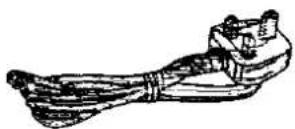

natural_image
Line drawing of a mobile phone with keypad and buttons (no text or symbols)Infra-red Remote Controller

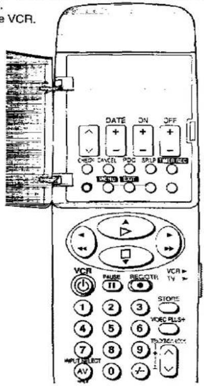
Set the VCR/TV switch to VCR to use the ∨ ∧, RESET, INPUT SELECT and the numeric buttons.
VCR OPERATION
1 Timer Recording Operation Buttons
∨ ∧, DATE, ON, OFF:
To programme a timer recording.
CHECK:
To check timer programmes.
CANCEL:
To cancel timer programmes.
PDC:
To set the PDC recording option or cancel the option.
SP/LP:
To select the tape speed desired for recording.
SP gives the best picture quality.
LP gives the longest recording time.
TIMER REC:
To turn the timer recording function on and off.
is lit or not lit.
Once operating timer recording function, the normal
VCR operation is not possible unless this button is set to off.
2 These buttons are not used to operate this VCR.
3 On Screen Display Menu Operation Buttons
The buttons with the green characters are used for the on screen display menu operation.
MENU: To make On Screen Display Main Menu appear on the TV screen.
EXIT: To exit the menu.
STORE: To confirm the selection, or to store.
▲▼◀▶: To make selections from On Screen Display.
- These buttons can also be used for the playback, stop rewind and fast forward mode.
4 VCR
Press to switch the VCR from on to standby mode or vice versa. In standby mode, the VCR is still connected to the mains.
5 PAUSE
During playback: Still picture. "00" is lit.
During recording: To interrupt recording
6 Numeric Buttons
Ensure that the VCR/TV switch is set to VCR.
• To select the programme positions (1-99) of the VCR.
19:

■To enter a PlusCode.
7 INPUT SELECT
To select the A1 or A2 external recording source:
- Ensure that the VCR/TV switch is set to VCR.
8 OSD
For the On Screen Display function.
9 DISPLAY
To change the indication on the VCR Display.
→Clock→Counter→Remaining Tape Time—
10 INDEX
For the index search function.
11 RESET
To reset the tape counter (elapsed time) to "0:00.00".
- The button performs the resetting function only when the "-" side is pressed.
- The tape counter is automatically reset to "0:00.00" when a video cassette is inserted.
- Ensure that the VCR/TV switch is set to VCR.
12 ∨ ∧
To select the required programme position (TV station) of the VCR.
For the tracking adjustment and vertical locking adjustment
- For manual tracking adjustment The √ (−) and ∧ (+) buttons are used to adjust the tracking when, for example, noise bars on the picture during normal playback are better removed manually than by automatic digital tracking control. Press both buttons down at the same time to return to automatic digital tracking control.
- For vertical locking adjustment Use the √ and ∧ buttons to minimize any vertical jitter during still picture playback.
Ensure that the VCR/TV switch is set to VCR.
13 VIDEO PLUS +
For the Video Plus÷ programming.
14 VCR/TV switch
VCR: To select the VCR operation mode.
TV: To select the TV operation mode.
15 REC/OTR
To start a recording.
For One-Touch Recording (OTR).
16 (REWIND)
In the stop mode: To rewind the tape. In the playback mode: To search backward. In the rewind mode: To obtain high speed picture. "<<" is lit.
▷ (PLAY)
To start playback. "> " is lit.
▶▶ (FAST FORWARD)
In the stop mode: To fast forward the tape.
In the playback mode: To search forward.
In the fast forward mode: To obtain high speed picture.
"▷▷" is lit.
□ (STOP)
To stop any playback or recording.
17 Infra-red Transmitter
TV OPERATION
Setting the Remote Controller for Operation of your TV Panasonic television only can be operated with provided remote controller.
1 First, confirm that the TV can be operated correctly with the remote controller.
2 If the TV does not operate correctly, press the TV button while pressing the VCR button on the remote controller. Then confirm that the TV can be operated correctly with the remote controller.
3 If the TV does not operate correctly still, press the AV button while pressing the VCR ⏻ button on the remote controller. Then confirm that the TV can be operated correctly with the remote controller.
- Some TV models cannot be operated using this remote controller.

18 Numeric Buttons
To select programme positions (1–99) of the TV.
- Ensure that the VCR/TV switch is set to TV.
19 AV
To select TV input.
- Ensure that the VCR/TV switch is set to TV.
20 TV
Press to switch the TV from on to standby mode or vice versa. In standby mode, the TV is still connected to the mains.
- With some TV models, it may only be possible to switch the TV to the standby mode using the button. In this case, use the numeric buttons, AV or ∨ ∧ to switch the TV on.
21
To adjust the volume of the TV.
- Ensure that the VCR/TV switch is set to TV
22 ∨ ∧
To select the required programme position (TV station) of the TV.
- Ensure that the VCR/TV switch is set to TV.
Power Source for the Remote Controller
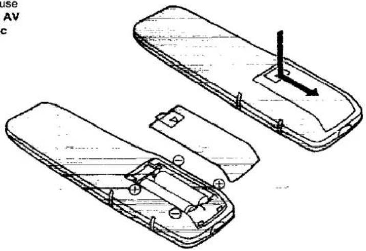
The remote controller is powered by 2 "AA", "UM3" or "R6" size batteries. The life of the batteries is about one year, although this depends on the frequency of use.
Precautions for Battery Replacement
- Load the new batteries with their polarity (⊕ and ⊖) aligned correctly.
- Do not apply heat to the batteries, or an internal short-circuit may occur.
- If you do not intend to use the remote controller for a long period of time, remove the batteries and store them in a cool and dry place.
- Remove spent batteries immediately and dispose of them.
- Do not use an old and a new battery together, and never use an alkaline battery with a manganese battery.
Installing the Batteries
Controls and Connection Sockets
This gives a detailed explanation of the function of each button and connection socket.

FRONT
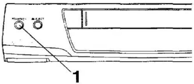
① POWER ⏻/l
Press to switch the VCR from on to standby mode or vice versa. In standby mode, the VCR is still connected to the mains.
② EJECT
To eject a video cassette.
③ Cassette Compartment
Insert a video cassette here.
4 (REWIND)
In the stop mode:
To rewind the tape.
In the playback mode:
To search backward.
In the rewind mode:
To obtain high speed picture.
"◀◀" is lit.
5 ▷ (PLAY)
To start playback. "▷" is lit.
6 ▶▶ (FAST FORWARD)
In the stop mode:
To fast forward the tape.
In the playback mode:
To search forward.
In the fast forward mode:
To obtain high speed picture.
">▷" is lit.
⑦ Infra-red Remote Control Receiver Window
⑧ CVC (Crystal View Control) Indicator
Indicates that the CVC function is active.
This indicator is always lit when the power is on.
9 Display
10 ∨ ∧
To select the required programme position (TV station).
- These buttons can also be used for the tracking adjustment and vertical locking adjustment.
13 REC/OTR
To start a recording.
For One-Touch Recording (OTR).
12 TIMER REC
To turn the timer recording function on and off.
is lit or not lit.
Once operating timer recording function, the normal
VCR operation is not possible unless this button is set
to off.
13 ■ (STOP)
To stop any playback or recording.
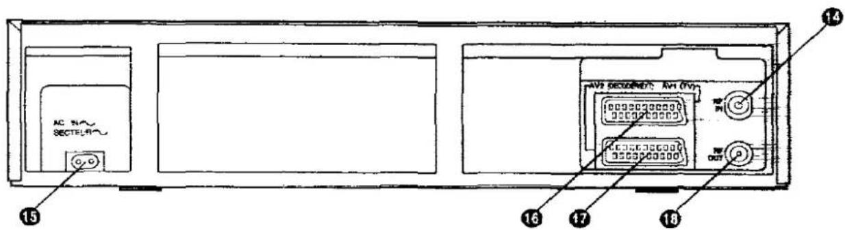
REAR
14 RF IN
To connect to the external aerial.
15 AC IN\~
To connect to the main power supply.
16 AV1 (TV)
This 21-pin scart terminal carries input and output signals for both picture and sound. TV sets equipped with a similar socket can be connected here.
This is also called Scart
Peritel
Euro Connector
Euro AV
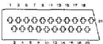
1 AUDIO OUTPUT 13 RED GROUND
2 AUDIO INPUT 14 BLANKING
3 AUDIO OUTPUT GROUND
4 AUDIO GROUND 15 RED
5 BLUE GROUND 16 BLANKING
6 AUDIO INPUT 17 VIDEO OUTPUT
7 BLUE GROUND
8 SWITCHING VOLTAGE 18 VIDEO INPUT
9 GREEN GROUND GROUND
10 No connection 19 VIDEO OUTPUT
11 GREEN 20 VIDEO INPUT
12 No connection 21 GROUND
Note:
RED, GREEN and BLUE (RGB) signals are loop-through only, not from tape playback, E.G. when connecting to a pay TV decoder.
17 AV2 (DECODER/EXT)
To connect to a decoder or another VCR.
●Only used as the input socket
18 RF OUT
To connect to the aerial terminal on a TV set.
Setting Up
Connections
This tells you how to connect with an aerial, TV, etc.
Tuning the TV to your VCR
The VCR supplies signals to the TV via an RF coaxial cable (supplied) or a 21-pin scart cable (not supplied). The RF output channel for use by the VCR to playback tapes or view TV programmes is automatically set during Auto Setup and indicated on the VCR display to aid TV tuning to the VCR channel.
Your TV must be tuned into this channel in order to view the playback picture.
If the connection to the TV includes the 21-pin scart cable, the playback picture can be viewed by selecting AV on your TV.
Auto Setup
When the VCR is turned on after connecting the aerial lead and the mains lead, Auto setup (Auto tuning and Auto clock setting) starts.
This tells you how to connect with an aerial, TV, etc.
Basic Connections
The following connections are required to record and play back the VCR through TV set:
● After making this connection, refer to page 14.

Connection to a TV Set with 21-Pin Scart Terminal
●After making this connection, refer to page 15.

Connection to a Decoder
● After making this connection, refer to page 15.

Notes:
- "RGB" is an abbreviation for "RED/GREEN/BLUE" signals. If the TV with RGB input capability is connected to AV1 and the unit with RGB output capability is connected to AV2, the TV can receive RGB signal from the unit through the VCR.
- Use fully-wired 21-pin scart cable for the connection.
- Selection of RGB or normal video output is done by the external equipment connected to AV2 terminal.
- Set the RF output channel of the VCR to "-" (RF OFF) when the VCR is connected to the TV via the 21-pin scart cable.
See the bottom section on page 14. - When the decoder is connected to the AV2 socket, AV2 Connection must first be set to DECODER. (See page 36.)
Tuning the TV to your VCR
The VCR supplies signals to the TV via an RF coaxial cable (supplied) or a 21-pin scart cable (not supplied).
It is possible to view the video picture on your TV in the same way that you watch TV broadcasts.
If you have connected the VCR to the TV through the 21-pin scart terminal, then you do not need to follow the procedure mentioned below.

Operations
1


Turn on the VCR and TV.
2
VCR Display

Example:


VCR will start Auto-setup and search for an unoccupied channel for use by the VCR to playback tapes or view TV programmes.
When this is done, the RF output channel will be displayed on the VCR.
- Check that the number of the RF output channel has appeared on the VCR display and then proceed as follows.
3
On Screen Display

(During Auto setup)

(After Auto Setup)
Set the TV to an unused programme position, such as "0", then tune the TV to the channel number indicated on the VCR (refer to the operating instructions for your TV).
You should then be able to see the screens similar to those shown on the left.
- On Panasonic TV the programme number 0 should be selected to obtain best performance.
- When the VCR is turned on after connecting the aerial lead and the mains lead, Auto setup (Auto tuning and Auto clock setting) starts.
4
EXIT

Press EXIT to leave this screen.
- In some rare cases after Auto-setup, interference may be visible on the picture. To avoid the interference, you can manually adjust the RF output channel: a few steps up or down from the current setting.
To change the RF output channel setting, use the remote controller:
1 Keep MENU pressed for 5 seconds or more.
- The VCR display changes as in step 2 and the VCR picture on the TV displays this test pattern.

natural_image
Abstract black-and-white striped pattern with no text or symbols2 Enter the desired channel number (21–69) by using the numeric buttons or the ∨ ∧ buttons.
3 Press STORE to finish the setting mode.
- Retune your TV to the new RF channel for the VCR.
To set RF output channel of the VCR to "-" (RF OFF) when the VCR is connected to the TV via 21-pin scart cable.
Press the "0" numeric button or the ∨ ∧ buttons to display "--".

Auto Setup
When the VCR is turned on after connecting the aerial lead and the mains lead, Auto setup (Auto tuning and Auto clock setting) starts.
On Screen Display

- The Auto setup is searching for TV station from minimum to maximum and memorizing the data for every programme position.
- The Auto setup takes two or more minutes to complete the search for TV station and the clock setting.
- If the clock setting screen appears after auto setup has been completed, refer to page 37 and proceed with the setting.
Note:
If VCR is not correctly set by Auto setup, see Various Settings on pages 32-34 and 37.
Viewing the TV station list
Use the following steps to confirm that the Auto setup is correctly set.
Preparations
- Confirm that the TV is on and the VCR viewing channel is selected.
●Turn on the VCR.

1 Press MENU.

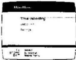
2 Select Station list.


3 Select the desired TV station, if you want to view the broadcast.

flowchart
graph TD
    A["Store"] --> B["EXIT"]
    C["To leave the Menu."] --> D["Exit"]
    style A fill:#fff,stroke:#000
    style B fill:#fff,stroke:#000
    style C fill:#fff,stroke:#000
    style D fill:#fff,stroke:#000

flowchart
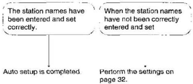
graph TD
    A["The station names have been entered and set correctly."] --> B["Auto setup is completed"]
    C["When the station names have not been correctly entered and set"] --> D["Perform the settings on page 32."]
Basic Operations
Playback
Manual Recording
One-Touch Recording (OTR)
Playback
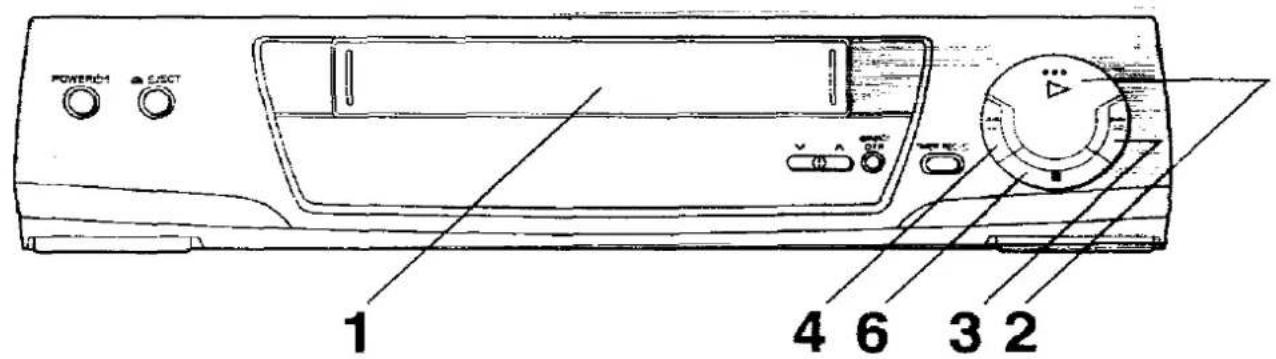
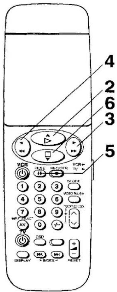
Operations Display Symbols
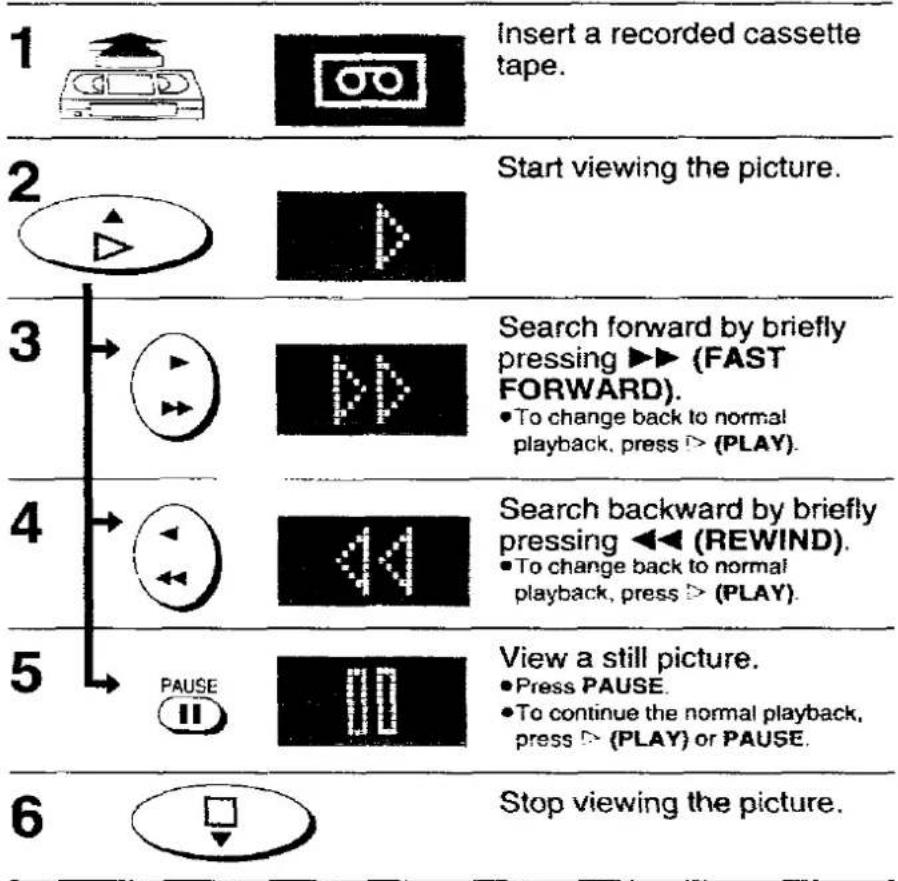
Note:
If you keep ▶▶ (FAST FORWARD) or ◀◀ (REWIND) pressed in step 3 or 4, search playback is activated while the button is pressed, and operation returns to normal playback when the button is released.
Other Playback Functions
To obtain High Speed Picture during
Fast Forward or Rewind
Keep ▶▶ (FAST FORWARD) pressed during fast forward.
Keep ◀◀ (REWIND) pressed during rewind.


Notes:
- Cue or review will be automatically released after 10 minutes, and still playback after 5 minutes.
- In "LP" mode only:
-
During any playback mode other than normal playback, the picture may have some noise bars, the colour may be unstable, or a black and white picture may appear.
-
When playing back a tape which was recorded on another VCR, it may be necessary to adjust the Tracking Control. In some cases the picture quality may still be inferior. This is due to limitation of format.

Manual Recording
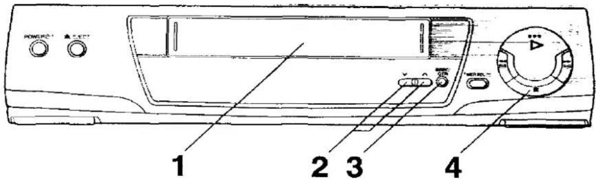
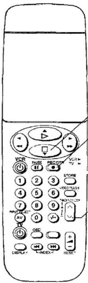
Operations Display Symbols

To select the Desired Tape Speed
Press SP/LP before recording.


SP gives the best picture quality.
LP gives the longest recording time.
To interrupt Recording
Press PAUSE during recording.
Press again to continue recording.


To record One TV Programme while Viewing Another Programme
1 Refer to the manual recording operations steps 1 to 3 (page 20).
2 Select the TV programme on your TV set you wish to view at the present time.
To display the Approximate Remaining Tape Time
1 Select Tape Length from On Screen Display and select the corresponding cassette tape length. See page 36.
On Screen Display

flowchart
graph TD
    A["Store"] --> B["Store"]
    B --> C["EXIT"]

◀ E-180: For E30, -60, -90, -120 and -180 tapes.
E-195: For E195 tape.
E-240: For E240 tape.
E-260 ▶: For E260 and -300 tapes.
2 Press DISPLAY.

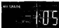
→Clock→Counter→Remaining Tape Time
●The remaining tape time may not be displayed correctly depending on the tape used.
Notes:
- When a video cassette with a broken off tab is inserted, the "cc" indication will flash to indicate that recording is not possible.
●The recording pause mode will be automatically released after 5 minutes and be back to the stop mode.


natural_image
Line drawing of a portable electronic device front panel with control buttons and a rotary knob (no text or symbols)
One-Touch Recording (OTR)
Whenever you are in a hurry to start a timer recording with automatic stop in your absence, simply set the recording duration by pressing REC/OTR repeatedly.
The duration indicated on the VCR display changes by pressing REC/OTR as follows:

flowchart
graph LR
    A["Counter display (normal recording mode)"] --> B["30 (min)"]
    A --> C["240 (min)"]
    A --> D["180 (min)"]
    A --> E["120 (min)"]
    A --> F["60 (min)"]
Preparation
Insert a video cassette with an intact erasure prevention tab.
Operations
1 Ready the video source which is to be recorded, and start recording.
2 Press REC/OTR repeatedly to select the desired recording duration.
REC/OTR

- The VCR will automatically switch off when OTR is completed. To turn the VCR on again, press POWER ⏻/I (VCR ⏻).
Notes:
•The OTR function works only in the normal recording mode
- When the tape reaches its end during OTR, the VCR will turn itself off.
- To stop OTR at any time, press □ (STOP) or POWER ⏻/I (VCR ⏻).
Advanced Operations
Timer Recording
Using On Screen Display
Up to 8 timer programmes can be recorded up to one month in advance by setting the timer, including weekly and daily programmes.
Programming the Video Plus+ PlusCode
Editing
Assembly Editing
This enables you to record a new segment immediately after a previously recorded segment.
Other Functions
On Screen Display
VHS Index Search System
Other Automatic Functions
Timer Recording
Using On Screen Display
Up to 8 timer programmes can be recorded up to one month in advance by setting the timer, including weekly and daily programmes.
Preparations
- Insert a video cassette with an intact erasure prevention tab.
- Confirm that the TV is on and the VCR viewing channel is selected.
For Example:
Programme position (channel); 2
Date: 27th. October
Starting time: 20:02
Ending time: 21:30
(Present date: 16th, October)
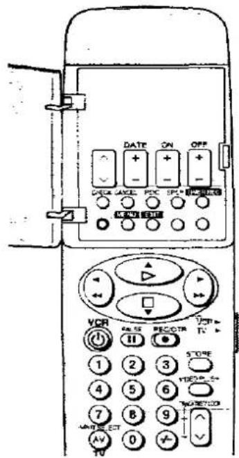
Follow the operation guide on screen display.
Operatons
1 Press MENU, and then press STORE to access Timer recording. •Timer recording is selected normally.

flowchart
graph LR
    A["MENU"] --> B["Store Icon"]
    B --> C["Monitor Icon"]
    C --> D["On Screen Display Panel"]
2 Press STORE again.
- The unoccupied position (blank line) is selected normally.
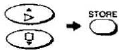
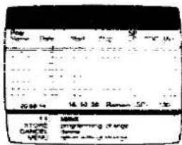
3 Set Programme position (channel) "2".
●An alternative method is to press ▲ ▼ ◀ ▶.

4 Set Date "27/10".
DATE


5 Set Starting time "20:02".
- When it is kept pressed, the indication changes in 30-minute steps.


6 Set Ending time "21:30".


7 Select the desired Tape speed (SP/LP).

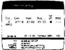
8 Select PDC ON or OFF (---).
- If PDC is set to ON, ensure that the starting time is the same as published time.
- See page 26 for PDC recording.


Press STORE.
- For the setting other programmes in succession, repeat steps 2–9.

10 To activate timer recording, press TIMER REC.

Weekly Timer Recording
In step 4, select the desired day by pressing ▼ or DATE —.
Daily Timer Recording
For this timer function, several groups of days can be selected.
Ⓐ Daily recording from Monday to Friday.
B Daily recording from Monday to Saturday.
© Daily recording from Sunday to Saturday.
In step 4, select the desired days by pressing ▼ or DATE —.
Timer Recording from External Signal Source
If Timer Recording is performed by a unit connected to the AV1 (TV) or AV2 (DECODER/EXT) Socket, select the A1 or A2 indicator for the programme position.
A1: Through the AV1 (TV) socket.
A2: Through the AV2 (DECODER/EXT) socket.
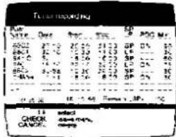
Checking a Timer Programme
- The VCR must be turned on, or the timer recording indicator "☐" is lit.
- Confirm that the TV is on and the VCR viewing channel is selected.
Press CHECK.

- On Screen Display may be distorted in the PDC recording standby mode.
Cancelling a Timer Programme
●The VCR must be turned on or in timer recording standby mode.
- Confirm that the TV is on and the VCR viewing channel is selected. CHECK
1 Press CHECK.

2 Select the desired timer programme.

3 Press CANCEL.


Notes:
- Either the Position number or the Station name is displayed here.
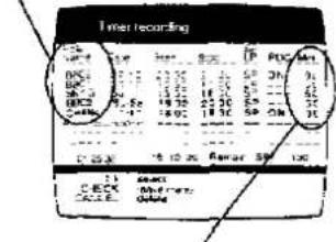
- For Daily and Weekly timer recording, the recording time for only one recording session is displayed.
Checking the Remaining tape time for recording:
This displays the remaining time for the inserted tape.
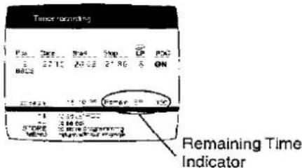
- This indicator is not displayed unless the remaining tape time has already been indicated on the VCR display. Refer to page 21.
PDC (Programme Delivery Control) How to use PDC?
(1) The VCR detects if broadcast stations transmit PDC signal or not at the time of "Auto-setup" only, and stores this information in its memory. If broadcast stations introduce or discontinue PDC transmission later on, "Auto-setup" must be carried out again to update the VCR's memory.
(2) PDC mode will be automatically set to "ON" when using "Video Plus+" codes for timer programming, if the stations have been memorised by the VCR as having PDC transmission.
PDC mode will be automatically set to "OFF" if the start time is altered during timer programming.
(3) PDC mode will be automatically set to “----” (no PDC) when using “Video Plus+” codes for timer programming, if the stations have not been memorised by the VCR as having PDC transmission.
(4) PDC mode will be automatically set to "OFF" when timer programming is done, for any station, by the "On-Screen" timer recording method, because the start time can be entered freely by the user. To use PDC recording in this case, if the station transmits PDC signal, set PDC mode to "ON" and ensure that the start time is set to exactly the same as the published time, e.g. in newspapers, magazines, etc. If this is not done correctly, recording will not start.
Notes on PDC recording:
(1) PDC recording will start approximately some seconds before the broadcast programme commences and may stop some seconds before or after the end of the programme, depending on the control from the broadcaster.
(2) Normally programmed timer recording data is automatically cancelled after recording is completed. Under the following conditions the programmed timer recording data will be automatically cancelled at 4 a.m. of the next day.
(a) If PDC signal cannot be detected during PDC timer recording, the VCR will perform normal timer recording (without PDC).
(b) If a timer recording is incomplete due to insufficient tape or cancellation by the user.
(c) If timer recording is still in progress at 4 a.m.
(d) If the broadcaster transmits a PDC signal to suspend or interrupt the recording. If these cases, the VCR will remain in the timer standby condition after timer recordings have been completed.
(3) If PDC is set to "ON" manually for the station which does not have PDC transmission, the VCR will perform normal timer recording (without PDC).
(4) In case of multiple timer programmings, while the VCR is in timer standby mode the VCR will periodically check PDC status of the programmed stations with PDC in turn for any change in the start time of each programme. But while the VCR is recording a programme, it can only check the PDC status of that programme being recorded.
(5) If the actual broadcasting times of timer recordings overlap (regardless of whether they are PDC-controlled), the recording that starts first always has priority, and the recording of the later programme will start only after the first timer recording has finished.
(6) Some broadcasting stations send signals which change the programming information (channel, day on which the programme is scheduled to be aired, and its start and end times). In a case like this, the display at the PDC item on the On Screen Display programming screen changes to "ON". When a change has been made in this way, what has been programmed can be cleared but it cannot be changed.
(7) When the name of a broadcasting station has been changed by manual tuning, the programmed recording may not be performed correctly even when PDC is ON.
Programming the Video Plus+ PlusCode
Programming is now easier than ever: simply enter the PlusCode provided in the programme schedule column carried by newspapers and magazines.
PlusCodes are numbers which are assigned to each programme listed in the TV programme schedule carried in newspapers and TV guides. When these codes are entered and STORE is pressed, the codes are converted into the actual programming.
Preparations
- Insert a video cassette with an intact erasure prevention tab.
- Confirm that the TV is on and the VCR viewing channel is selected.
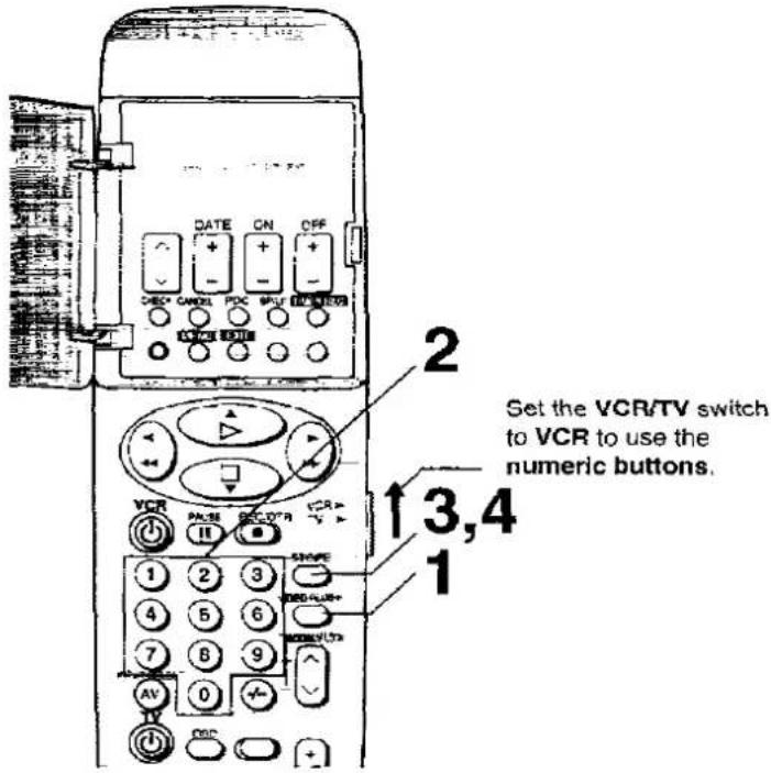
- Ensure that the VCR/TV switch is set to VCR.
Operations
1 Press VIDEO PLUS+.
VIDEO PLUS+

2 Enter a Video PlusCode for the TV programme to be recorded.
Example: 920216
3 Press STORE.

On Screen Display

- To extend the ending time or to make any corrections, use buttons ▲ ▼ ◀ ▶, √ ∧, DATE, ON, OFF or PDC.
- PDC will be set to ON automatically if the station has been memorised as having PDC transmission at the time of Auto setup. PDC can be set to OFF manually, if desired, by moving the highlight to PDC then using the PDC button.
When programming for the first time using a Video Plus+ code, “--” will appear for the programme position because the station
has been manually tuned:
In this case, select the programme position of your VCR which receives the TV station you entered the Video Plus+ PlusCode for at step 2 using button ▲▼ or √

- After several seconds have elapsed, the message display at the bottom of the OSD is replaced by the operation guide display.
- Once programming is performed after the programme position has been selected here, the guide channel will be automatically stored so that the correct position will appear when the Video Plus+ PlusCode for this station is next entered.
4 Press STORE once more to confirm. •The VCR will go into timer recording standby
STORE

Note:
The VCR will automatically change to the timer recording standby mode after about 1 minute, if STORE is not pressed.
5 When programming two or more programmes, repeat steps 1–4.
Notes:
●To select the desired tape speed, press SP/LP button after step 3.
●To release from the standby mode, press TIMER REC.
- When the PlusCode is used for programming, the recording time may be slightly longer than the actual programme time.
●The procedures for checking and cancelling a timer programme are the same as on page 25.
Editing
Assembly Editing
This function can be used to make up an edited tape from other recordings or video sources.
A new scene can be added to the end of a previous one.
Preparations
- Connect a movie camera or another VCR to this VCR as shown.
- Insert a recorded cassette tape with an intact erasure prevention tab.
- Select the video source required by pressing INPUT SELECT to set A1 or A2.
Ensure that the VCR/TV switch is set to VCR.
A1: Through AV1 (TV) socket.
A2: Through AV2 (DECODER/EXT) socket.


Operations
1 Search for the end of the previous recording.

2 Press PAUSE.

3 Press REC/OTR to switch the VCR from the pause mode to the recording standby mode. REC/OTR

4 Start the new recording by pressing PAUSE again.

5 Press □ (STOP) to stop recording.

On Screen Display
Press OSD to make the On Screen Display appear on the TV screen.
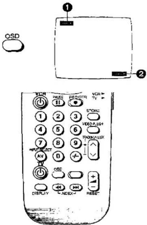
TV station
② OTR indication
Note:
When the item "On screen display" is set to OFF, the On Screen Display (except for the error message) will not appear. (See page 35.)
VHS Index Search System
It is very easy to find the beginning of each recording, because a special index signal is recorded at the start of each recorded segment on the tape.
Recording Index Signals
Index signals are recorded in following cases.
- When a recording is started by pressing REC/OTR.
- When timer recording is activated.
For example:
Searching for the 2nd recorded segment in the forward direction.
Press INDEX ▶▶1 twice during normal playback or stop mode.


- After finding the specific recorded segment, playback starts automatically.
- For the reverse direction, press INDEX ↖◀.
- Up to 20 programmes can be searched for in both directions.
- When the opposite INDEX button is pressed, the number shall be decreased till 1.
- The figure on the display is decremented by 1 each time an index signal is located. Bear in mind that the display will be decremented in this way even while either INDEX button is being pressed.
- The INDEX search function can only work correctly, if the index signals are spaced at least 3 minutes apart in the SP mode and 5 minutes apart in the LP mode.
Other Automatic Functions

natural_image
Line drawing of a front panel with handle, buttons, and control knob (no text or symbols)Automatic Playback
When a cassette without an erasure prevention tab is inserted, the VCR starts playback automatically.
VCR-off Playback
When the VCR is off, an inserted cassette can be played back by pressing > (PLAY).
Automatic Rewinding
When the tape reaches its end during recording (except for timer recording) or playback, it will automatically be rewound to the beginning.
During OTR, this function will not work.
Automatic Switching Off and Ejection
When the VCR is switched off, and inserted cassette can be ejected simply by pressing EJECT. The VCR will eject the cassette and automatically turn itself off again.
Various Settings
Storing TV Broadcasts into your VCR
The VCR is fitted with its own tuner (just like a normal TV set) and can be pre-set to receive up to 99 TV broadcast stations.
Settings Using On Screen Display
Setting the Clock of your VCR
The built-in clock is used to activate the timer for automatic recording and must be set to the correct time.
Storing TV Broadcasts into your VCR
Introduction
The VCR is fitted with its own tuner (just like a normal TV set) and can be pre-set to receive up to 99 TV broadcast stations.
When your video cassette recorder is plugged in for the first time, the Auto setup feature will tune in your channels automatically.
However, under certain circumstances in some transmission areas certain channels may not be assigned a channel name or their normal channel position. If this is the case they will need to be tuned manually. If Auto setup is not successful, please follow the steps below.
Preparation
Confirm that the TV is on and the VCR viewing channel is selected.

Manual Tuning Procedure
Follow the operation guide on screen display. Operations
1 Press MENU.


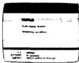
2 Select Settings.


3
Select Tuning.


4
Select Manual.

5
Select desired Programme position.


6
Select the Signal Transmission Channel (Ch) if known.

Use the numeric buttons. Example: 23 Ensure that the VCR/TV switch is set to VCR.
- Use ▲ ▼ to search for the station if channel number is not known.

7
Press MENU, and then press EXIT. - Repeat steps 5 to 7 if manual tuning for other station is required, before pressing EXIT.
Channel Plan
| VHF | UNF | |
| NV-SD220B | —— | 21-69 |
| NV-SD220BL | A-J(CATV: 104-470 MHz) | 21-69 |
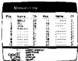
When changing (moving) the programme position, adding "Blank" positions and deleting stations:
These operations can be performed easily by following the indications of On Screen Display.

Press ▲ or ▼ to select the desired programme position (station), and then follow the steps indicated below.
←: Press ◀ to add "Blank" position. →: Press ▶ to change (move) the programme position.
CANCEL: Press CANCEL to delete the stations.
Entering the Station Name
Follow the steps 1 to 4 on page 32.
5 Select the station(s) named - : - : - for which you wish to setup name. Establish which channel you are viewing, by checking your TV Guide/Newspaper.

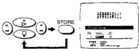
6 Highlight the TV station name.

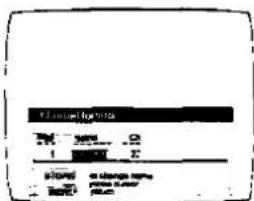
7 Enter characters into all five : + + + positions, from the table using the arrows and press STORE after each character. Use blank space if required, to enter a blank select the area between Z and .
flowchart
graph TD
    A["Store"] --> B["User Interface"]
    A --> C["User Interface"]
    A --> D["User Interface"]
    A --> E["User Interface"]
    A --> F["User Interface"]
    A --> G["User Interface"]
    A --> H["User Interface"]
    A --> I["User Interface"]
    A --> J["User Interface"]
    A --> K["User Interface"]
    A --> L["User Interface"]
    A --> M["User Interface"]
    A --> N["User Interface"]
    A --> O["User Interface"]
    A --> P["User Interface"]
    A --> Q["User Interface"]
    A --> R["User Interface"]
    A --> S["User Interface"]
    A --> T["User Interface"]
    A --> U["User Interface"]
    A --> V["User Interface"]
    A --> W["User Interface"]
    A --> X["User Interface"]
    A --> Y["User Interface"]
    A --> Z["User Interface"]
    A --> AA["User Interface"]
    A --> AB["User Interface"]
    A --> AC["User Interface"]
    A --> AD["User Interface"]
    A --> AE["User Interface"]
    A --> AF["User Interface"]
    A --> AG["User Interface"]
    A --> AH["User Interface"]
    A --> AI["User Interface"]
    A --> AJ["User Interface"]
    A --> AK["User Interface"]
    A --> AL["User Interface"]
    A --> AM["User Interface"]
    A --> AN["User Interface"]
    A --> AO["User Interface"]
    A --> AP["User Interface"]
    A --> AQ["User Interface"]
    A --> AR["User Interface"]
    A --> AS["User Interface"]
    A --> AT["User Interface"]
    A --> AU["User Interface"]
    A --> AV["User Interface"]
    A --> AW["User Interface"]
    A --> AX["User Interface"]
    A --> AY["User Interface"]
    A --> AZ["User Interface"]
    A --> BA["User Interface"]
    A --> BB["User Interface"]
    A --> BC["User Interface"]
    A --> BD["User Interface"]
    A --> BE["User Interface"]
    A --> BF["User Interface"]
    A --> BG["User Interface"]
    A --> BH["User Interface"]
    A --> BI["User Interface"]
    A --> BJ["User Interface"]
    A --> BK["User Interface"]
    A --> BL["User Interface"]
    A --> BM["User Interface"]
    A --> BN["User Interface"]
    A --> BO["User Interface"]
    A --> BP["User Interface"]
    A --> BQ["User Interface"]
    A --> BR["User Interface"]
    A --> BS["User Interface"]
    A --> BT["User Interface"]
    A --> BU["User Interface"]
    A --> BV["User Interface"]
    A --> BW["User Interface"]
    A --> BX["User Interface"]
    A --> BY["User Interface"]
    A --> BZ["User Interface"]
    A --> CA["User Interface"]
    A --> CB["User Interface"]
    A --> CC["User Interface"]
    A --> CD["User Interface"]
    A --> CE["User Interface"]
    A --> CF["User Interface"]
    A --> CG["User Interface"]
    A --> CH["User Interface"]
    A --> CI["User Interface"]
    A --> CJ["User Interface"]
    A --> CK["User Interface"]
    A --> CL["User Interface"]
    A --> CM["User Interface"]
    A --> CN["User Interface"]
    A --> CO["User Interface"]
    A --> CP["User Interface"]
    A --> CQ["User Interface"]
8 Press MENU once. If you wish to change or setup any other TV station names, repeat steps 5→8.

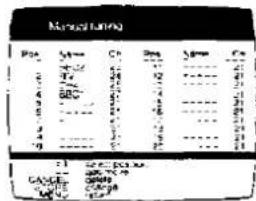
9 Press EXIT.
Changing the Programme Position
Follow the steps 1 to 4 on page 32, then follow the example below.
5 Select the station(s) named "BBC1".

flowchart
graph LR
    A["Store"] --> B["Manual User"]
    style A fill:#f9f,stroke:#333
    style B fill:#bbf,stroke:#333
6 Select the number location you want to set the channel.

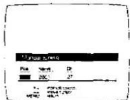
- Use the numeric buttons.
Example: 1 Ensure that the VCR/TV switch is set to VCR.
7 Press MENU once.


8 To amend other programme positions repeat steps 5→7.
9 When correctly tuned your station list will look like this. (Channel information will vary.)

- This is needed for using Video Plus+ PlusCodes correctly.
10 Press EXIT.
Note:
When channels have been set with manual tuning, the channel position will need to be entered in the highlighted box the first time Video Plus+ is used.
Auto Setup Restart
If the VCR is moved to a different TV transmission area, you may have to return your VCR. Follow the procedure below.
Follow the steps 1 to 3 on page 32.
4 Select Auto setup restart.
On Screen Display
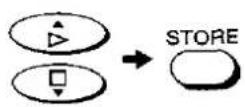
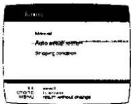
5 Press STORE.

●The auto setup screen may fail to appear temporarily.

flowchart
graph TD
    A["Auto Group"] --> B["Shopping container"]
    B --> C["Output Box"]
    C --> D["Next Step"]
Shipping Condition
If you want to return the VCR to the factory-preset condition, follow the procedure bellow.
Follow the steps 1 to 3 on page 32.
4 Select Shipping condition.

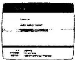
5 Press STORE.


6 Press STORE again.


- Since the RF output channel is initialized to 21 when Shipping Condition is executed, the TV picture may fail to appear.
Note:
To re-tune VCR, disconnect mains lead and then reconnect mains lead. The RF output channel is now searched automatically. If VCR is off, turn on the VCR. Auto setup will start automatically.
Settings Using On Screen Display
Preparations
- Confirm that the TV is on and the VCR viewing channel is selected.
●Turn on the VCR

VCR functions
On Screen Display
1 Press MENU, and then select Settings.

2 Select VCR functions.
3 Select On screen display.
4 Select ON or OFF.
ON: The On Screen Display will appear on the TV screen by pressing OSD.
OFF: The On Screen Display will not appear even if OSD is pressed.
5 Press STORE, and then press EXIT to make On Screen Display disappear.

To select the Corresponding Cassette Tape Length for Displaying the Approximate Remaining Tape Time
Follow steps 1 and 2 on page 35.
3 Select Tape Length.


4 Select the corresponding cassette tape length.


◀ E-180: For E30, -60, -90, -120 and -180 tapes.
E-195. For E195 tape.
E-240: For E240 tape.
E-260 ▶: For E260 and -300 tapes.
●The times displayed may differ depending on the tape used.
5 Press STORE, and then press EXIT to make On Screen Display disappear.

AV2 Connection
Follow steps 1 and 2 on page 35.
3 Select AV2 Connection.


4 Select VCR/SAT or DECODER.


VCR/SAT: When another VCR is connected to the AV2 socket.
DECODER: When the decoder is connected to the AV2 socket.
5 Press STORE, and then press EXIT to make On Screen Display disappear.

Setting the Clock of your VCR
The built-in clock is used to activate the timer for automatic recording and must be set to the correct time.
The built-in digital clock employs the 24-hour system.
If VCR is not correctly set by Auto setup, follow the procedure below.
Preparations
- Confirm that the TV is on and the VCR viewing channel is selected.
- Turn on the VCR.
Manual Clock Setting
Follow the operation guide on screen display.
Operations
1 Press MENU, and then select Settings.
2 Select Clock.
3 Select Manual setting.
4 Set Time (H/M).
- When it is kept pressed, the indication changes in 30-minute steps.
5 Set Date (D).
6 Set Month (M).
7 Set Year (Y).
On Screen Display
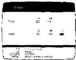
8 Press STORE.
•The clock will start.
9 Press EXIT.
Automatic Clock Setting
Follow steps 1 to 2 of the above procedure.
3 Select Automatic setting.

4 Press STORE.
●The clock is set automatically.
Notes:
- The clock operates for at least 60 minutes by its backup system in the event of power failure.
- When the item "Automatic clock-set is" is ON, on the on screen display, Automatic time correcting function is activated every day.
The Automatic time correcting function will only work when the VCR is in standby. This function will not work during timer recording standby mode.
Helpful Hints
Before Requesting Service
Before requesting service, check the following points once again.
Precautions
Please read these cautions before you operate this VCR.
Specifications
Before Requesting Service
Before requesting service, check the following points once again.
| Message of On Screen Display | ||
| MESSAGE | CAUSE | REMEDY |
| This action is not possible before time and date are set | VIDEO PLUS+ or TIMER REC is pressed when date and time is not set. | Set date and time. |
| Please insert video tape1 | REC/OTR, DIRECT TV REC, ▷ (PLAY), ▶▶ (FAST FORWARD) or ◀◀ (REWIND) is pressed when no cassette in the VCR. | Insert a video cassette. |
| Please use tape with recording tab intact! | REC/OTR or DIRECT TV REC is pressed without tab of Cassette. | Use a cassette with tab. |
| No timer recording programmes to be done' | TIMER REC was pressed even though nothing has been programmed. | Programme the timer recording. |
| Please put VCR into stop mode first! | VIDEO PLUS+ was pressed during a tape operation. | Set the VCR to the stop mode. |
●Other messages besides these may appear. Follow the instructions in the message.
| Self Test Indication | ||
| This VCR has a self-diagnosis and display function. If the VCR detects trouble during installation or during use, the following indications automatically appear in the VCR display. Indications are displayed in the form of a single English letter plus two numbers such as [H01]. | ||
| INDICATION | CAUSE | REMEDY |
| H□□ | Some trouble has occurred.(Numbers following H and F differ according to the status of the VCR.) | Consult your dealer for further advice. |
| F□□ | ||
| VCR will not operate correctly | |||
| SYMPTOM | CAUSE | REMEDY | CHECKED |
| VCR display is not illuminated. | Mains lead is not connected. | Reconnect mains lead to VCR. | |
| VCR display is illuminated but VCR will not operate. | VCR is in timer mode. | Press TIMER REC to operate VCR manually. | |
| Safety devices are operating. | Disconnect mains lead and wait for 1 minute.Reconnect mains supply and check functions. | ||
| VCR picture does not appear on TV screen. | The RF output channel is set to “—” (RF OFF). | Set the RF channel to a setting other than “—” (RF OFF). See page 14. | |
| Playback will not operate correctly | |||
| SYMPTOM | CAUSE | REMEDY | CHECKED |
| Picture noisy or not in colour. Horizontal bars or lines run down the screen. | Tracking is not correct. | Adjust the tracking. See page 7. | |
| TV set is not tuned to VCR. | Tune the TV to your VCR. See page 14. | ||
| Video heads are clogged or worn. | Consult your dealer for further advice.Head cleaning by service agent is not covered by warranty. | ||
| Recording will not operate correctly | |||
| SYMPTOM | CAUSE | REMEDY | CHECKED |
| "20" indication flashes whenever recording is attempted. | Erasure prevention tab on cassette is broken off. | Use the video cassette with intact erasure prevention tab, or cover tab hole with adhesive tape, if original recording is no longer required. | |
| Picture is recorded with noise or blank screen. | Aerial or aerial lead is defective. | Check aerial connection to VCR. See page 12. Check your normal TV picture. If there is no picture, check your aerial. | |
| VCR is not correctly tuned. | Re-tune VCR. See pages 32-34. | ||
| A1 or A2 is selected. | Select the required TV programme. | ||
| Timer recording cannot be performed. | Clock or calendar is incorrectly set. | Check clock and calendar. Set to present time. (Note this is a 24 hour clock.) See page 37. | |
| Recording start or end time setting is incorrect. | Set recording start and end time correctly. | ||
| VCR is not set for timer recording. | Press TIMER REC after programming for timer recording. | ||
| AV external recordings cannot be made. | A1 or A2 is not selected. | Select A1 or A2 by pressing INPUT SELECT. | |
| External AV connections are incorrect. | Check that connections for external video and audio source are correct. See page 28. | ||
| Remote controller will not work correctly | |||
| SYMPTOM | CAUSE | REMEDY | CHECKED |
| Remote controller does not operate correctly. | Remote controller transmitter beam is not reaching VCR. | Ensure that remote controller is being pointed at VCR and that transmitter beam is not obstructed. | |
| Distance is too far. | Use remote controller within 7 m of VCR. If this range is not possible, replace batteries. | ||
| Batteries are exhausted. | Replace batteries. Note precaution for replacement on page 8. | ||
| Batteries are incorrectly fitted with (+/−) reversed. | Fit batteries correctly as shown on page 8. | ||
Please read these cautions before you operate this VCR.
Avoid Sudden Changes in Temperature
If the VCR is suddenly moved from a cold place to a warm place, condensation may form on the tape and inside the VCR.
Humidity and Dust
Avoid places where there is high humidity or much dust, which may cause damage to internal parts.
Do Not Obstruct the Ventilation Holes
The ventilation holes prevent abnormal increases in temperature. Do not block or cover these holes. Especially avoid covering the holes with soft materials such as cloth or paper.
Keep away from High Temperature
Keep the VCR away from extreme direct heat such as direct sunlight, heating radiators, or closed automobiles.
Keep Magnets away
Never bring a magnet or magnetized object near the VCR because it will adversely affect the performance of the VCR.
No Fingers or Other Objects Inside
Touching internal parts of this VCR is dangerous, and may cause serious damage to the VCR. Do not attempt to disassemble the VCR. There are no user serviceable parts inside.
Keep Water away
Keep the VCR away from flower vases, tubs, sinks, etc. CAUTION: If liquids are spilled into the VCR, serious damage could occur. If you spill any liquid into the VCR, consult qualified service personnel.
Cleaning the VCR
Wipe the VCR with a clean, dry cloth. Never use cleaning fluid, or other chemicals. Do not use compressed air to remove dust.
Stacking
Place the VCR in a horizontal position, and do not place anything heavy on it.
Video Head Clogging
The video heads place picture signals on the tape during recording and read picture signals from the tape during playback and they are, therefore, of critical importance for the picture quality. If the VCR is used over extremely long periods of time, these heads may become dirty and clogged. In such a case, the signals can no longer be recorded correctly, and the playback picture will be distorted accordingly. This is the case, for example, during the playback of a tape, the sound is reproduced normally, but no picture is seen, or the picture is greatly distorted. When such a symptom case occurs have the recorder checked by qualified service personnel.
Head cleaning by service agent is not covered by warranty.
Condensation may form in the VCR if:
●The VCR is in a room where the heater has just been turned on.
• The VCR is in a room with steam or high humidity.
- The VCR is brought from cold surroundings into a well-heated room.
- The VCR is suddenly brought from cool surroundings, such as an air-conditioned room or car, to a place which is hot and humid.
Note:
Do not operate the VCR for at least 1 hour if any of the above conditions occur.
This VCR does not incorporate a dew sensor.
Tape Care
Some do's and don'ts on tape care.
DO:
1) Use a good quality branded tape, such as Panasonic.
2) Keep in the Box supplied with your tape, or a video case, when not in use.
3) Try to use all the tape on a cassette by making recordings not only at the tape start but also in the middle and end sections. This will avoid many repeated recordings at the beginning of the tape resulting in premature wear.
4) Take care to insert a tape correctly into the VCR to avoid damage.
DO NOT:
1) Expose the tape to high humidity or temperature.
2) Expose to liquid.
3) Expose to dust particles by storing directly on a carpet for example.
4) Use a damaged tape or attempt to repair.
5) Dismantle the cassette housing.
6) Attempt to lift the front cassette flap or touch the tape surface.
Specifications
NV-SD220B...(U.K. model)
NV-SD220BL...(EIRE model)
| Power Source: | 220-240 V AC 50/60 Hz | |
| Power Consumption: | 19 watts | |
| Video Recording System: | 2 rotary heads, helical scanning system | |
| Video Heads: | 2 heads | |
| Tape Speed: | SP; 23.39 mm/sec.LP; 11.7 mm/sec. | |
| Tape Format: | VHS tape | |
| Record/Playback Time: | SP; 240 min. with NV-E240LP; 480 min. with NV-E240 | |
| VIDEO | ||
| Television System: | CCIR; 625 lines, 50 fields, PAL colour signal | |
| Modulation System: | Luminance; FM azimuth recordingColour signal; converted subcarrier phase shift recording | |
| Input Level: | AV1/AV2; | 1.0 Vp-p,75 ohm, terminated |
| Output Level: | AV1/AV2; | 1.0 Vp-p,75 ohm, terminated |
| RF Modulated; (U.K. model) UHF channel 21-69.(EIRE model) UHF channel 21-69. | 75 ohm75 ohm | |
| AUDIO | ||
| Input Level: | AV1/AV2; | -6 dBV,more than 10 kohm |
| Output Level: | AV1/AV2; | -6 dBV,less than 1 kohm |
| Audio Track: | 1 track (Normal-mono only) | |
| Video Horizontal Resolution: | Colour, more than 240 lines (SP) | |
| Signal-to-Noise Ratio: | Video; more than 43 dB (SP)Audio; more than 43 dB | |
| Audio Frequency Response: | 80 Hz-10 kHz | |
| Operating Temperature: | 5°C-40°C | |
| Operating Humidity: | 35%-80% | |
| Weight: | 4.2 kg | |
| Dimensions: | 430 (W)×99.9 (H)×297 (D) mm | |
| Standard Accessories: | 1 pc. RF Coaxial Cable1 pc. Remote Controller2 pcs. "R6" size batteries1 pc. AC Mains Lead | |
Weight and dimensions shown are approximate.
Specifications are subject to change without notice.
- Panasonic
- Dear Customer
- Video Plus+ Programming System
- Crystal View Control
- PDC (Programme Delivery Control) What is PDC?
- IMPORTANT
- WARNING
- FOR YOUR SAFETY
- Contents
- Setting Up
- Basic Operations
- Advanced Operations
- Various Settings
- Helpful Hins
- How to replace the Fuse
- Infra-red Remote Controller
- VCR OPERATION
- Timer Recording Operation Buttons
- INPUT SELECT
- OSD
- DISPLAY
- INDEX
- RESET
- ∨ ∧
- VIDEO PLUS +
- VCR/TV switch
- REC/OTR
- (REWIND)
- ▶▶ (FAST FORWARD)
- □ (STOP)
- Infra-red Transmitter
- TV OPERATION
- Numeric Buttons
- AV
- TV
- 21
- ∨ ∧
- Power Source for the Remote Controller
- Precautions for Battery Replacement
- Controls and Connection Sockets
- FRONT
- REAR
- RF IN
- AC IN\~
- AV1 (TV)
- AV2 (DECODER/EXT)
- RF OUT
- Connections
- Tuning the TV to your VCR
- Auto Setup
- Basic Connections
- Connection to a TV Set with 21-Pin Scart Terminal
- Connection to a Decoder
- Notes:
- Operations
- Note:
- Viewing the TV station list
- Preparations
- Playback
- Manual Recording
- Other Playback Functions
- To obtain High Speed Picture during
- Fast Forward or Rewind
- Operations Display Symbols
- To select the Desired Tape Speed
- To interrupt Recording
- To record One TV Programme while Viewing Another Programme
- To display the Approximate Remaining Tape Time
- One-Touch Recording (OTR)
- Preparation
- Timer Recording
- Editing
- Other Functions
- Using On Screen Display
- For Example:
- Operatons
- Press STORE again.
- Set Programme position (channel) "2".
- p#g## # #####
- b#####
- Set Date "27/10".
- Set Starting time "20:02".
- Set Ending time "21:30".
- Select the desired Tape speed (SP/LP).
- Select PDC ON or OFF (---).
- Press STORE.
- To activate timer recording, press TIMER REC.
- Weekly Timer Recording
- Daily Timer Recording
- Timer Recording from External Signal Source
- Checking a Timer Programme
- Cancelling a Timer Programme
- Checking the Remaining tape time for recording:
- PDC (Programme Delivery Control) How to use PDC?
- Notes on PDC recording:
- Programming the Video Plus+ PlusCode
- Press STORE.
- Assembly Editing
- On Screen Display
- VHS Index Search System
- Recording Index Signals
- Other Automatic Functions
- Automatic Playback
- VCR-off Playback
- Automatic Rewinding
- Automatic Switching Off and Ejection
- Storing TV Broadcasts into your VCR
- Settings Using On Screen Display
- Setting the Clock of your VCR
- Introduction
- Manual Tuning Procedure
- When changing (moving) the programme position, adding "Blank" positions and deleting stations:
- Entering the Station Name
- Changing the Programme Position
- Auto Setup Restart
- Shipping Condition
- VCR functions
- To select the Corresponding Cassette Tape Length for Displaying the Approximate Remaining Tape Time
- ON*26
- AV2 Connection
- ##
- Manual Clock Setting
- Automatic Clock Setting
- Helpful Hints
- Before Requesting Service
- Precautions
- Specifications
- Avoid Sudden Changes in Temperature
- Humidity and Dust
- Do Not Obstruct the Ventilation Holes
- Keep away from High Temperature
- Keep Magnets away
- No Fingers or Other Objects Inside
- Keep Water away
- Cleaning the VCR
- Stacking
- Video Head Clogging
- Head cleaning by service agent is not covered by warranty.
- Condensation may form in the VCR if:
- Tape Care
- DO:
- DO NOT:
Marque : PANASONIC
Modèle : NV-SD220B
Catégorie : Magnétoscope