
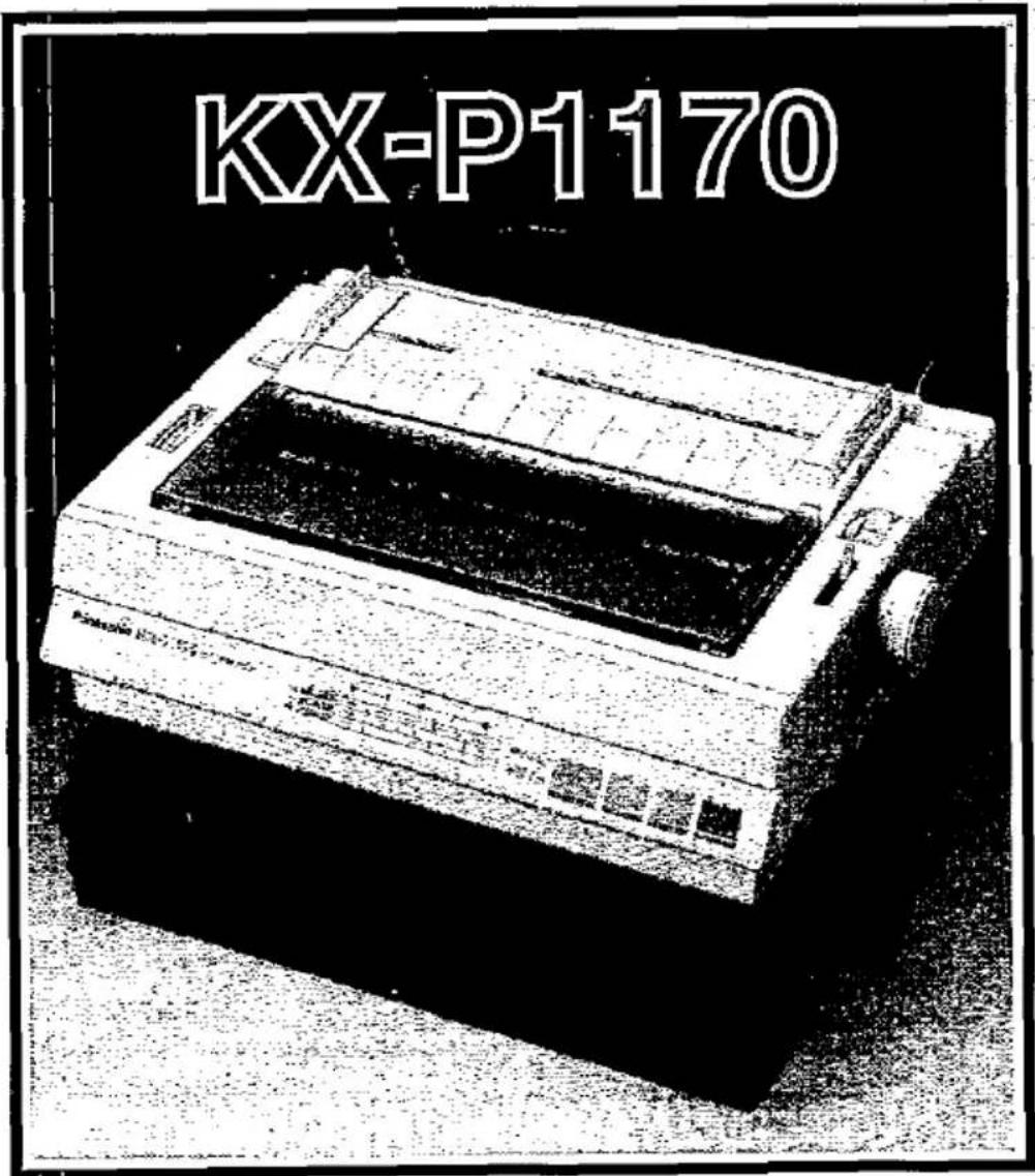
KX-P1170 - Imprimante PANASONIC - Notice d'utilisation et mode d'emploi gratuit
Retrouvez gratuitement la notice de l'appareil KX-P1170 PANASONIC au format PDF.


| Type de produit | Imprimante matricielle 9 aiguilles |
| Marque | Panasonic |
| Modèle | KX-P1170 |
| Vitesse d'impression | Jusqu'à 180 cps (Draft), 30 cps (LQ) |
| Résolution | 240 x 216 dpi |
| Interface | Parallèle Centronics (IEEE 1284) |
| Alimentation papier | Tracteur avant et arrière, friction |
| Formats papier supportés | A4, A5, Letter, Legal, enveloppes, étiquettes |
| Capacité du bac papier | 100 feuilles (bac standard) |
| Dimensions (L x P x H) | 400 x 250 x 150 mm |
| Poids | 4,0 kg |
| Alimentation électrique | 220-240 V, 50/60 Hz |
| Consommation électrique | En veille : 10 W, En impression : 50 W |
| Niveau sonore | Environ 50 dB (A) |
| Types d'impression | Texte et graphiques, copie carbone (1 original + 2 copies) |
| Jeux de caractères | ASCII, IBM PC, Epson FX, etc. |
| Rouleau d'encre | Cartouche ruban compatible KX-PC31 |
| Entretien et nettoyage | Nettoyer l'extérieur avec un chiffon doux et sec. Utiliser une bombe d'air comprimé pour les parties internes. |
| Sécurité | Ne pas exposer à l'humidité. Débrancher avant entretien. |
| Pièces détachées et réparabilité | Cartouche ruban KX-PC31, guide papier, tracteur. Indice de réparabilité : 7/10 (estimation) |
| Informations générales | Imprimante robuste idéale pour formulaires en continu. Compatible DOS et Windows. |
FOIRE AUX QUESTIONS - KX-P1170 PANASONIC
Questions des utilisateurs sur KX-P1170 PANASONIC
0 question sur cet appareil. Repondez a celles que vous connaissez ou posez la votre.
Poser une nouvelle question sur cet appareil
Téléchargez la notice de votre Imprimante au format PDF gratuitement ! Retrouvez votre notice KX-P1170 - PANASONIC et reprennez votre appareil électronique en main. Sur cette page sont publiés tous les documents nécessaires à l'utilisation de votre appareil KX-P1170 de la marque PANASONIC.
MODE D'EMPLOI KX-P1170 PANASONIC
Operating Instructions
Impact Dot Matrix Printer
Panasonic
Before operating this unit, please read these instructions completely.
FOR USE IN U.K.
IMPORTANT:
The wires in the main leads are coloured in accordance with the following code:
Green and yellow: Earth
Blue: Neutral
Brown: Live
As the colours of the wires in the main lead of this apparatus may not correspond with the coloured markings identifying the terminals in your plug, proceed as follows:
●The wire which is coloured green and yellow must be connected to the terminal in the plug which is marked by the letter E or by the safety earth symbol ± or coloured green or green and yellow.
●The wire which is coloured blue must be connected to the terminal which is marked with the letter N or coloured black.
●The wire which is coloured brown must be connected to the terminal which is marked with the letter L or coloured red.
WARNING: This apparatus must be earthed.
●This equipment is produced to BS800: 1988.
Any details given in these Operating Instructions are subject to change without notice.
WARNING
●To prevent fire or shock hazard, do not expose this product to rain or any type of moisture.
●Power source voltage of this unit is listed on the nameplate. Do not fail to plug the printer into an outlet with the proper voltage.
- When you operate this equipment, the socket-outlet shall be near the equipment and shall be easily accessible.
The serial number of the unit may be found on the label on the rear of the unit.
For your convenience, note this number below, and retain this book, along with your proof of purchase, to serve as a permanent record of your purchase in the event of a theft, or for future reference.
MODEL NO. KX-P1170
NAME OF DEALER ____
SERIAL NO. ____
DATE OF PURCHASE ____
Microsoft is a registered trademark of Microsoft Corporation.
IBM and IBM-PC are registered trademarks of International Business Machines Corporation.
IBM Proprinter II and IBM NLQ II are trademarks of International Business Machines Corporation.
Apple is a registered trademark of Apple Computer, Inc.
FX-86e/FX-800 is a trademark of Seiko Epson Corporation.
Page
1. Introduction 1-1
1.1 Product Overview 1-1
1.2 Specifications 1-2
1.3 Names of the Parts 1-5
The Front View 1-5
The Top View 1-6
The Right View 1-7
The Rear View 1-7
2. Set up 2-1
2.1 Site Requirements 2-1
2.2 Unpacking and Inspection 2-1
2.3 Mounting the Ribbon Cassette 2-2
2.4 Power Up 2-4
2.5 Adjusting the Printhead Gap 2-4
2.6 Paper Installation 2-5
A. Single Sheet and Envelopes 2-5
B. Fanfold Paper from Rear 2-7
C. Fanfold Paper from Bottom 2-10
2.7 Self Test 2-13
2.8 Connecting to a Computer 2-14
2.9 DIP Switches 2-15
3. Operation 3-1
3.1 Front Panel Switches 3-1
FUNCTION Switch 3-1
ON LINE/FONT Switch 3-1
FF/PITCH Switch 3-1
LF/FORM LENGTH Switch 3-1
3.2 Control Table 3-2
A. Setting Font/Pitch/Form Length 3-2
3.3 Feeding the paper 3-4
A. Memo Load (LOAD/PARK) 3-4
B. Aligning the Top of Form 3-5
3.4 Detectors 3-6
Out of Paper Detector 3-6
Overheat Detector 3-6
3.5 Initialization 3-7
3.6 Hex Dump 3-7
4. Software Introduction 4-1
4.1 Introduction 4-1
4.2 Control Codes 4-1
4.3 Entering Control Codes through Commercial Software Packages 4-2
4.4 Entering Control Codes Directly from the Keyboard 4-4
4.5 Entering Control Codes from Within a Program ..... 4-5
4.6 Entering Hexadecimal Code 4-5
4.7 Control Codes 4-6
4.8 Special Code IBM PC or Compatible 4-7
5. KX-P1170 Features 5-1
5.1 Print Feature Control 5-1
5.2 Download Characters 5-3
5.3 Bit Image (Graphics) 5-21
6. Software Commands 6-1
7. Interfacing 7-1
8. Maintenance.... 8-1
Appendix A Character Set Tables ...... A-1
Appendix B Proportional Spacing Tables ...... B-1
Appendix C Download Character Matrix Blanks ...... C-1
Appendix D Paper ...... D-1
Appendix E Printing Area ...... E-1
Index I-1
OPTIONS and SUPPLIES
1. Introduction
1.1 Product Overview
This printer is a versatile, high quality 9-pin matrix printer which is designed to meet the needs of your office.
This printer features the EZ Set Operator Panel that lets you control a wide variety of printing conditions quickly and conveniently from the panel.
●Font selections consist of Draft and 3 Near Letter Quality (NLQ) fonts
● Pitch selections consist of 10, 12, 17 characters per inch and PS (Proportional Spacing)
- Form Length selections consist of 8, 8.5, 11, 11 12 13 and 12 inches
●By using MEMO LOAD a single sheet or an envelope can be printed without removing or wasting the fanfold paper
● And more...
The printer has landscape insertion capability and 3 paper paths; rear, bottom and top.
The KX-P1170 offers burst speeds up to 192 cps (characters per second) in draft-elite mode or 38 cps in NLQ-elite (Near Letter Quality) mode.
The printer is equipped with an internal 6K buffer. An optional 32K buffer is available which expands the total buffer size to 38K. The entire buffer area can be used as a receiving buffer or a portion can be used as a download font area. When the 32K buffer option is installed, the buffer area assignment is automatically selected.
For software compatibility, this printer has two command sets: Epson FX-86e/FX-800 and IBM Proprinter II. Either set can be selected by DIP switches. Refer to Section 2.9.
1-1 Introduction
1.2 Specifications
| Power requirements: Frequency: Current: | Refer to the nameplate located on the rear of the printer. | ||
| Interface: | Centronics Parallel, RS-232C Serial, Apple Interface (option) | ||
| Printing fonts: | Draft (Pica&Elite), Near Letter Quality (Courier, Bold PS, Prestige, Sans Serif*), Dot Graphics | ||
| Software emulation: | Epson FX-86e/FX-800 (Standard Mode), IBM Proprinter II (IBM Mode) | ||
| Character set: | 96 ASCII characters, 96 Italic ASCII characters, 32 International characters (13 countries), 32 Italic International characters (13 countries), 158 IBM special characters | ||
| Dot configuration: | 0.3 mm (3/254 inch) dot diameter | ||
| Draft (Pica) | NLQ | Sans Serif* | |
| Dot alignment (Hor.×Ver.) | 9×9 | 18×18 | 18×9 |
| Dot pitch (Hor.) | 0.21 mm (1/120") | 0.11 mm (1/240") | |
| (Ver.) | 0.35 mm (1/72") | 0.18 mm (1/144") | |
| Maximum number of characters per line (cpl) | Pica (10 cpi) | 80 cpl | |
| Elite (12 cpi) | 96 cpl | ||
| Micron (15 cpi) | 120 cpl | ||
| Compressed (17 cpi) | 137 cpl | ||
| Elite compressed (20 cpi) | 160 cpl | ||
| Pica elongated (5 cpi) | 40 cpl | ||
| Elite elongated (6 cpi) | 48 cpl | ||
| Semi Compressed elongated (7.5 cpi) | 60 cpl | ||
| Compressed elongated (8.5 cpi) | 68 cpl | ||
Sans Serif* is IBM NLQ.
| Printing speed: | Draft-Elite | 192 cps |
| Draft-Pica | 160 cps | |
| NLQ-Elite | 38 cps | |
| NLQ-Pica | 32 cps |
| Printing direction: | Text printing (Draft, NLQ): Bidirectional |
| Bit Image printing: Unidirectional | |
| (left to right) |
| Line feed time: | Approx. 100 msec[with 4.2 mm (1/6 inch) line feeding] |
| Paper feed: | Tractor feed (with fanfold paper)Friction feed (with single sheets or envelopes) |
| Paper used: | Fanfold paper:Width: 102~254 mm {4~10 inches}Weight: pull mode: 18~24 lbs (68~90 g/m2)push mode: 16~20 lbs (60~75 g/m2)Single sheets:Width: 102~297 mm {4~11.7 inches}Height: 127~363 mm {5~14.3 inches}Weight: 41~90 g/m2 {14~24 lbs.}Envelopes:Standard business envelopeie: # 10 size(Refer to Appendix D.) |
| Copies: | Push: Original + 1 non-carbon copyPull: Original + 3 non-carbon copies |
| Paper thickness: | Total thickness of sheets must be less than 0.32 mm {0.013 inch} |
| Operating environment: | 50°F (10°C) to 95°F (35°C) temperature, 30~80% humidity(Please allow the printer to stabilize at room temperature within the operating temperature range before operation.) |
| Storage environment: | -4^ ( -20^ ) to 140^ ( 60^ ) temperature, 1090% humidity |
1-3 Introduction
Head life: Approx. 100 million characters in draft mode
Ribbon: Cassette seamless fabric ribbon Ink colour: Black Yield: Approx. 4 million characters in draft mode
Dimensions: 423(W)×341(D)×133(H) mm {16.7"×13.4"×5.2"}
Mass {weight}: Approx. 6.9 kg {15.2 lbs.}
1.3 Names of the Parts
The Front View

1-5 Introduction
The Top View

The Right View

The Rear View

1-7 Introduction
2.1 Site Requirements
This printer can be installed in any normal home or office environment.
No special wiring or cooling is required.
However, do not use the printer under the following conditions:
—extremely high or low temperature [temperature range: 50\~95°F (10\~35°C)]
—extremely high or low humidity (humidity range: 30\~80% RH)
—areas of poor ventilation [a minimum of 4" (10 cm) clearance on all sides is necessary to insure proper ventilation]
—areas of high dust concentration
—areas with chemical fume concentration
—areas with extreme vibration or when placed on an unstable or unleveled surface
2.2 Unpacking and Inspection
Having opened the shipping carton, carefully remove the contents. Inspect the printer and accessories for damage. Report damage or shortages to the store from which the unit was purchased. Inside the manual's front cover, record all important information regarding the printer.
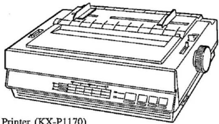
natural_image
Line drawing of a printer (KX-P1170) showing internal components and ports (no text or symbols on the diagram itself)Printer (KX-P1170)

natural_image
Isometric line drawing of a mechanical device with internal components and a central knob (no text or symbols)Ink ribbon cassette (KX-P115i)
natural_image
Simple line drawing of a rectangular block (no text or symbols)Operating manual
Note:
- Please keep all the packing materials so they may be used should you wish to transport the printer in the future. They are specifically designed to protect your printer during shipment.
2.3 Mounting the Ribbon Cassette
-
Make sure the printer is turned off. To remove the smoked plastic cover.
-
Gently slide the printhead carriage toward the centre of the unit.

-
Be sure the head gap lever is in the (+) position.
-
Prior to installing the cassette, remove any slack in the ribbon by rotating the knob on the cassette counterclockwise.

- Position the cassette over the carriage and lower it into place, inserting its rear end first as shown ① Visually insure that the ribbon slips between the nose cover and the nose of the print head. Gently, but firmly press down on the cassette until the two wing tab snap into place ②

- Replace the smoked plastic cover.
- Set the head gap lever to the proper position. Refer to the Section 2.5 on next page.
Note:
Because the printhead may be extremely hot, use caution when cover is open.
To remove the ribbon cassette, spread the wing tab and lift up the cassette.

2.4 Power Up
Plug the power cord into an outlet of the proper rating as listed on the nameplate located at the rear of the printer.
The power switch is located on the right side of the printer toward the front. When power is supplied to the printer, the power indicator light on the front panel will be lit.
2.5 Adjusting the Printhead Gap
The distance between the printhead and platen can be adjusted to compensate for the thickness of the paper.
The 6-position head gap lever moves the printhead closer to or farther away from the platen approximately 0.0028 inch (0.07 mm) per step. To narrow the gap move the lever forward (-).
To widen the gap move the lever backward (+).
Note:
- If an ink smear occurs when loading paper or during printing, move the lever toward the lower position (+) until the smear no longer appears.

2-4 Set up
2.6 Paper Installation
The paper feed mechanism uses friction for single sheet paper or envelopes and tractors for fanfold paper. Alternating between the two is accomplished by using the lever on the right side of the printer labeled "F" (friction) and "T" (tractor). In the friction mode the paper is held by pinch rollers which press the paper against the platen. The tractor mode is for use with fanfold paper. You can insert the fanfold paper from either the rear or bottom of the printer. Rear feeding allows continuous forms to be torn off without wasting a copy between printouts.
A. Single Sheet and Envelopes
To install a single sheet of paper or envelope, follow these procedures:
- Turn the power switch ON. The paper out indicator blinking.
- Verify that the head gap lever is in the (+) position.
- Set the paper feed selector in the "F" position.

- Raise the top cover and insert the paper behind the platen. Use the markings and paper guide on the top cover as a guide.

natural_image
Line drawing of a printer with paper feed and paper roll, showing mechanical components (no text or symbols)Set up 2-5
-
Pull the paper bail release lever toward the front of the printer to wrap the paper automatically around the platen.
-
Press down and hold the Line Feed switch (LF) or rotate the platen knob to advance the paper.
-
To align the paper horizontally or vertically, set the Paper feed selector to the "T" position. This releases the pinch rollers and allows the paper to be positioned manually as required. Set the selector back to "F" before printing.

natural_image
Line drawing of a printer with paper feed and control knobs (no text or symbols)-
Set the head gap lever to the appropriate thickness of the paper being used. Refer to Section 2.5 on page 2-4.
-
Push the paper bail release lever toward the rear.
B. Fanfold Paper from Rear
The following steps describe how to load Fanfold Paper from the rear of the printer:
-
Turn the power switch ON. The paper out indicator blinking.
-
Verify that the head gap lever is in the (+) position.
-
Set the paper feed selecter to the "T" position.

- Remove the top cover as shown below. Lift to most upright position, then slightly lower and pull back.

natural_image
Line drawing of a printer with paper feed and paper roll, labeled 'Set' (no text or symbols on the diagram itself)Set up 2-7
- Unlock the tractors by pulling the tractor clamping levers forward. Slide the tractors out toward the sides to the approximate width of the paper.

- Insert the paper so that the sprocket holes align with and catch on the tractor pins.

-
Rotate the platen knob to advance half-way around.
-
Pull the paper bail release lever toward you. The printer will rotate the paper about half-way around the platen.
-
Press down and hold the Line Feed switch (LF) to advance the paper and stop the paper just before it reaches the smoked plastic cover.
-
Centre the paper horizontally using the ruler on the smoked plastic cover.
-
Lock the tractors into position by pushing the tractor clamping levers back.
-
Push the paper bail release lever toward the rear.
-
Set the head gap lever to the appropriate thickness of the paper being used. Refer to Section 2.5 on page 2-4.
-
Rotate the platen knob in the reverse direction to adjust printing position.
-
Replace the top cover.
C. Fanfold Paper from Bottom
The following steps describe how to load fanfold paper from the bottom of the printer:
- Turn the power switch ON. The paper out indicator blinking.
- Verify that the head gap lever is in the (+) position.
- Set the paper feed selector to the "T" position.
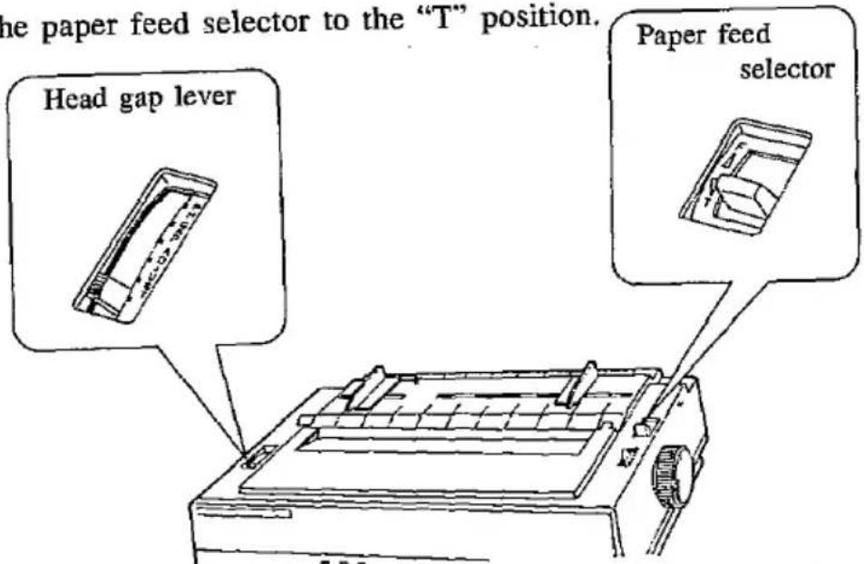
- Remove the top cover as shown below. Lift to most upright position, then slightly lower and pull back.
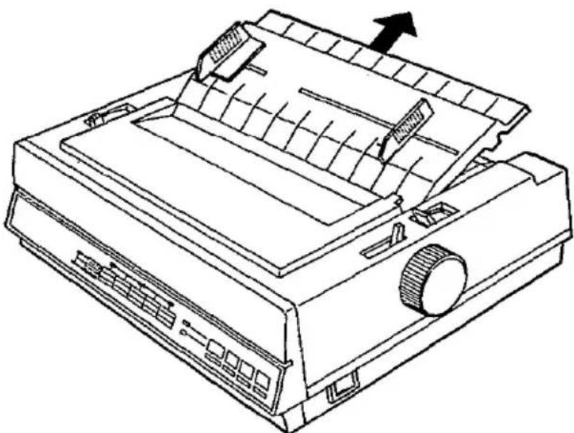
natural_image
Line drawing of a printer with paper feed and paper tray, showing internal structure and no text or symbols2-10 Set up
- Unlock the tractors by pulling the tractor clamping lever forward. Slide the tractors out toward the sides to the approximate width of the paper.
Tractor clamping levers

-
Space the center paper support evenly between the tractors.
-
Open both tractor covers.
-
Insert the paper from the bottom opening of the printer.
-
Pull the paper until it reaches the tractor pins.

natural_image
Line drawing of hands using a printer to press or spread materials (no text or symbols present)-
Align the paper sprocket holes with the tractor pins and close the tractor covers.
-
Pull the tractors outward to remove any slack, then lock the tractors into position by pushing the tractor clamping lever back.

natural_image
Technical illustration of a mechanical assembly with internal components and directional arrows (no text or symbols)-
Set the head gap lever to the appropriate thickness of the paper being used. Refer to Section 2.5 on page 2-4.
-
Replace the top cover.
Note:
● When feeding paper from the bottom:
- To insure proper paper feeding, the paper bail release lever must be placed in the open position (ie: toward the front of the printer).
- If you use the functions accompanied with reverse feed, such as ESC+j, ESC+w (Standard Mode) and ESC+[+@ (IBM Mode) commands, the printer will not feed correctly and print out result may not be correct.
2.7 Self Test
The printer has a self test feature which allows the user to test the printer. The mode is entered by turning on the power switch while pressing the LF switch. First, all ASCII characters will be printed in draft and all four NLQ fonts in 10 cpi. Then they will be printed in draft mode for approximately 15 minutes. To release the self test mode, turn the power switch off. It is also possible to print out a list of the current DIP switch settings, allowing the user to check the settings without moving the printer. This feature is activated by turning on the power switch while pressing the FF switch.
2.8 Connecting to a Computer
The computer communicates with the printer through an interface cable which you must purchase separately. The printer comes with a Centronics parallel interface.
-
Be sure the power switches of both the printer and the computer are turned off.
-
Plug one end of the cable into the connector of the printer and snap the clips into place.

If the cable has a frame ground wire, connect it to the frame ground terminal.
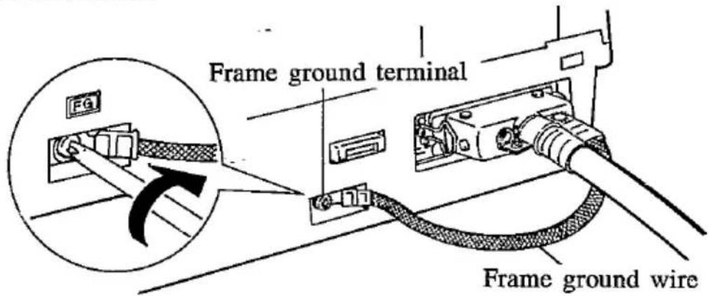
- Plug the other end of the cable into the connector of the computer.
Note:
- If the connectors are not alike make sure to plug the appropriate end into each device.
● A RS-232C serial interface and Apple interface are available as an option.
- See Section 7 "Interfacing" for detailed information.
2.9 DIP Switches
The DIP switches allow the user to set the initial condition of the printer when the power is on.
The following figure shows the location of them.
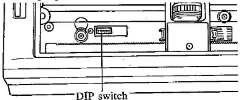
-Changing the DIP switch settings
-
Turn the power off.
-
Set the switches' to your desired position with a sharp edged instrument.
-
Turn the power on.
The settings are read into memory automatically.
DIP Switch 1
| SWITCH NUMBER | FUNCTION | ON | OFF | POSITION WHEN SHIPPED |
| SW1 | Printer Mode | IBM Mode (Proprinter II) | Standard Mode (FX-86e/FX-800) | OFF |
| SW2 | Skip Perforation | 1 inch (25.4 mm) skip | No skip | OFF |
| SW3 | Automatic LF | CR + LF | CR only | OFF |
| SW4 | Cut Sheet Feeder (Option) | Installed | Not Installed | OFF |
| SW5 | 7/8 bit | 7 bit | 8 bit | OFF |
| SW6 SW7 SW8 | Character Set | SW1=ON: See IBM Proprinter II Character Set Chart SW1=OFF: See International Character Set Chart | OFF | |
| OFF | ||||
| OFF | ||||
When DIP Switch 1 is OFF (Standard Mode)
International Character Set
| SW6 | SW7 | SW8 | INTERNATIONAL CHARACTER SET |
| OFF | OFF | OFF | USA |
| ON | OFF | OFF | FRANCE |
| OFF | ON | OFF | GERMANY |
| ON | ON | OFF | ENGLAND |
| OFF | OFF | ON | DENMARK 1 |
| ON | OFF | ON | SWEDEN |
| OFF | ON | ON | ITALY |
| ON | ON | ON | SPAIN 1 |
When DIP Switch 1 is ON (IBM Mode)
| SWITCH NUMBER | FUNCTION | ON | OFF |
| SW6 | Character Set | Set 2 | Set 1 |
| SW7 | Automatic CR | Causes Auto CR on LF, VT, ESC+J | Prevents Auto CR on LF, VT, ESC+J |
| SW8 | Zero font | Zero slash ∅ | Zero 0 |
SW1 Printer Mode
ON IBM Mode
OFF Standard Mode
Each printer mode has the following character set. IBM character sets are selected by SW6 when SW1 is set to ON.
Standard Mode
| ASCII | = | 96 |
| Italic ASCII | = | 96 |
| International | = | 32 |
| Italic International | = | 32 |
IBM Character Set 1
| ASCII | = | 96 |
| Special Characters | = | 95 |
IBM Character Set 2
| ASCII | = | 96 |
| Special Characters | = | 158 |
Refer to Appendix A for the character set charts.
SW2 Skip Perforation
ON A 3 Line margin is skipped before and after the perforation between pages.
OFF Printing is continuous, NO margins along perforation.
The setting can be changed by software. Refer to page 6-34.
SW3 Automatic LF
ON A Line Feed command (LF) is added to each Carriage Return (CR).
OFF Carriage Return only.
SW4 Cut Sheet Feeder
ON C.S.F. installed
OFF C.S.F. not installed
This setting is effective only when the paper feed selector is in the "F" position and the cut sheet feeder option (KX-P37) is installed.
SW5 7/8 Bit Code Selection
ON 7 BIT
OFF 8 BIT
This switch selects the size of the data word. If the computer sends a 7 bit word, the printer must also be set for 7 bits. If the two settings do not agree, random errors will occur and meaningful communication will not be possible.
SW6, 7 & 8 Character Set
The combination of these switch settings is used with the SW1 setting to select one of 8 International character sets or IBM Modes. The character set diagrams are located in Appendix A.
The International character sets are selected when the SW1 is set to OFF.
The IBM Modes are selected when the SW1 is set to ON.
SW6 (IBM mode)
ON IBM Character Set 2
OFF IBM Character Set 1
The IBM modes are selected when the SW1 is set to ON.
The character set diagrams are located in Appendix A.
SW7 (IBM mode)
ON Causes Automatic CR on LF, VT, ESC+“J”.
OFF Prevents Automatic CR on LF, VT. ESC+"J".
SW8 (IBM mode)
ON Zero slash (∅)
OFF Zero (0)
3.1 Front Panel Switches
This printer has an EZ Set Operator Panel with four switches and a Control Table. These switches allow you to select various features and functions of the printer.
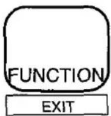
FUNCTION / EXIT switch
This switch allows you to enter and exit the FUNCTION mode. The FUNCTION mode allows you to operate the Control Table. When activated the ON LINE indicator will blink.

ON LINE / FONT switch
This switch opens and closes the communication lines with the computer. When open, the ON LINE indicator is lit and allows information to be sent from the computer to the printer. When closed or OFF LINE, the ON LINE indicator will not be lit and does not allow information to be sent to the printer. In the FUNCTION mode, this switch allows you to set Font on the Control Table.
FF / PITCH switch
This switch advances the paper to the next top of form. It is active in the OFF LINE mode or when the printer is not printing in the ON LINE mode.
In the FUNCTION mode, this switch allows you to set Pitch on the Control Table.

LF / FORM LENGTH switch
In the OFF LINE mode or when the printer is not printing in the ON LINE mode, this switch advances the paper one line at a time.
In the FUNCTION mode, this switch allows you to set Form Length on the Control Table.
3.2 Control Table
The setting of the Control Table is used to make temporary changes in font, pitch and form length.
A. Setting Font/Pitch/Form Length
- Press the FUNCTION switch to enter the FUNCTION mode. The ON LINE/FUNCTION indicator will start blinking.
2. Setting Font
Press and release the ON LINE/FONT switch to reach the desired font.
Setting Pitch
Press and release the FF/PITCH switch to reach the desired pitch.
Setting Form Length
Press and release the LF /FORM LENGTH switch to reach the desired form length.
- Press the FUNCTION switch to exit the FUNCTION mode.
| Selects type | ROW lights |
| FONT | R1 □□□R2 □□ |
| PITCH | R1 □□□R2 □□ |
| FORM LENGTH | R1 □□R2 □□ |

| COLUMN lights | |||||||
| C1 C2 C3■ □ □ | C1 C2 C3■ ■ □ | C1 C2 C3□ ■ □ | C1 C2 C3□ ■ □ | C1 C2 C3□ ■ □ | C1 C2 C3□ ■ □ | C1 C2 C3□ □ □ | |
| PGM* | DRAFT | COURIER | PRESTIGE | BOLD PS | |||
| PGM* | 10 | 12 | 17 | PS | |||
| 11" | 12" | 1113 " | 8" | 8.5" | |||
(*Initial Setting when power is switched ON, confirm the Form Length by turning on the power switch while pressing the FF switch.)
3-2 Operation
EXAMPLES
FONT: DRAFT

PITCH: 12

FORM LENGTH: 8

Note:
- When C1 (first column) indicator is on, the printer is in PGM mode which allows software to determine which Font and/or Picth will be used.
● The setting of Form Length also can be changed through software commands, overriding the Control Table settings. Changes through software commands will not be reflected in the Control Table indicator.
3.3 Feeding the paper
You can adjust the paper position by using the front panel switch when the printer is in the OFF LINE mode or when the printer is not printing in the ON LINE mode (but never in the FUNCTION mode).
3
Form Feed
Pressing the FF switch advances the paper to the next top of form position.
Line Feed
Pressing the LF switch once advances the paper one line. Multiple line feeds can be accomplished by holding the switch down.
A. Memo Load (LOAD/PARK)
This printer can use single sheets, envelopes and fanfold paper. You can insert a single sheet or envelope without removing the fanfold paper:
To print on the single sheet
- Verify the Paper feed selector is in "T" position and the power is ON.
- Tear off the printed pages of the fanfold paper.
- Pull the bail lever to retract the fanfold paper.
- Set the paper feed selector to "F" position.
- Insert a single sheet. Then, pull the paper bail lever to load.
After printing on the single sheet
- Remove the single sheet by pulling paper bail lever or pressing FF switch.
- Set the paper selector to "T" position.
- Pull the paper bail lever to reload the fanfold paper.
3-4 Operation
B. Aligning the Top of Form
This printer has a line counter which keeps track of the vertical position of the printhead. Each time power is turned on, the line counter is reset and the current position of the printhead is designated as line one.
To set the Top of Form
- Set the FORM LENGTH of the paper you are using through the Control Table (see page 3-2) or software commands.
- Load the paper by pulling the paper bail release lever (see Section 2.6)
- Adjust the paper position by rotating the platen knob or using LINE FEED.
- Turn off the power switch.
- Wait for few seconds, then turn printer on. Now, line counter is reset on the current position.
Note:
● The vertical position of the printhead is 6.9 mm (0.27") far from the top edge of the back tension plate.
- When Bottom feeding, do not use this function.
3.4 Detectors
Out of Paper Detector
The out of paper detector is located under the platen and senses the absence of paper. When an out of paper condition occurs, printing stops, the printer goes to the OFF LINE mode and the PAPER OUT light starts blinking. To continue printing to the end of current page when out of paper condition occurs, press the ON LINE switch repeatedly until the page is completed. To start printing the next page, install new paper and press the ON LINE switch. The printer will resume printing.
Note:
● The out of paper detector can be disabled by a software command.
Overheat Detector
If the printer is printing continuously for extended periods of time, the print head may become overheated. When this occurs, an internal protective circuit will cause the printer to pause until the head temperature decreases sufficiently. Having attained normal temperature, the printer will automatically resume printing without loss of data. This feature is included to extend the life of the printhead.
3.5 Initialization
The printer is initialized under the following conditions:
— the AC power is turned ON
— the PRIME signal is received
— the RESET command is received
When the printer is initialized, the following conditions are set:
— the print buffer is cleared
— the receive buffer is cleared (Except RESET PRINTER command)
— the download character buffer is cleared by a PRIME signal in Standard Mode. The download character buffer is not affected by PRIME in IBM Mode or RESET PRINTER command in Standard Mode.
— the DIP switches are read and printer modes set (Except RESET PRINTER command)
— horizontal tabs are set every 8 columns
— vertical tab settings are cleared
— all modes set by control and escape commands will be cleared (Except download font and NLQ selected by IBM Mode in PRIME signal)
— present form position is designated as top of form
— the Self Test mode is cleared.
— the Control Table settings are read and set (Control Table settings are not changed by PRIME signal or RESET PRINTER command*) the printhead goes to the home position (Except RESET PRINTER command)
* Some software packages send PRIME signal at the beginning of their programs. Print modes set by the Control Table will not change.
3.6 Hex Dump
In this mode, all data received from the computer is printed in hex code instead of the normal ASCII characters. Function codes for the printer (CR, LF, HT, etc.) are not executed. This mode is very useful for debugging programs.
To enter the Hex Dump mode:
Turn the power on while pressing both LF and FF switches.
To release the Hex Dump mode:
Turn the power off, then back on.
4. Software Introduction
4.1 Introduction
In order for a computer to communicate with a printer, both pieces of equipment must understand a common language or coding scheme. One such coding scheme is called ASCII (American Standard Code for Information Interchange). For example, the ASCII code can express the character "K" in any of the following forms:
(01001011) 2 -Binary 4B hex , 4B h -Hexadecimal 75 DEC , 75 _D -Decimal
Many computers allow you to enter ASCII codes in either hexadecimal or decimal form. The entered ASCII codes are converted to binary form by the computer and then sent to the printer.
In the following sections, you will see how to enter various ASCII codes to enable the printer to perform the functions you would like. Since the decimal equivalent of the ASCII code is most commonly used, all examples which follow will use the decimal form.
Appendix A contains the ASCII character and control command tables used by this printer.
4.2 Control Codes
The various printer functions are set through the use of control codes, which consist of one or more ASCII characters entered into the computer in a special way. These control codes often differ from printer to printer. Control codes generally fall into two categories: one-byte control codes and multi-byte control codes. The multi-byte control codes are often referred to as Escape Sequences since each code begins with the ASCII code for the ESCAPE character (ESC). Such an ESC character should not be confused with the Escape Key found on some computer keyboards.
Control codes can be sent to this printer from your computer in different ways. The three most common ways are:
4-1 Software Introduction
●Through commercial software packages
●Directly from the keyboard
●From within a user-written program
The latter two methods will specifically reference the BASIC language, although other languages such as FORTRAN, PASCAL, etc., can also be used. We will use BASIC since it is a relatively easy language to use. In addition, it is one of the most commonly used microcomputer languages.
4
4.3 Entering Control Codes through Commercial Software Packages
Many computer users do not have the time, the expertise, or the interest to develop software suited for their applications. In such cases software written by professionals can be purchased. Such software should be selected not only to meet the needs of the user, but must also be compatible with both computer and printer.
Commercial software is often written with what is called a driver. A driver is that part of the software which allows the user to configure the package to the type of printer and interface being used. Once the software has been booted, the user is generally requested to supply additional information (based on emulation or compatibility setting) such as:
● Brand/Model/Emulation mode of printer being used.
●I/O port being used (e.g.: LPT1:, if a parallel interface is being used.)
● Baud rate, parity, etc. if a serial interface is being used.
But how do you know which mode to choose? The major factor to consider is which printer your software supports. Most commercial software packages include printer drivers that support one or more of the printers that this printer can emulate.
The installation program usually offers a menu of printers from which to choose. If you find this printer on the menu, select it.
- Choices in order of priority: [If your DIP switch is set to Standard mode.
We recommend that you inspect your software first. If it offers a menu of supported printers, select the printer mode in this order of preference:
a. Panasonic KX-P1170
b. Panasonic KX-P1180
c. Epson FX-86e/FX-800
d. Epson FX Series
- Choices in order of priority (IBM mode)
a. IBM Proprinter II
Once the necessary information has been supplied, the software will provide the computer with the control codes and other data needed by this printer.
Many word processing packages will request that you enter the ASCII codes used by this printer for special settings such as underlining, compressed print, super- and subscript, italics, etc. In all cases you should refer to your software instruction manual for the proper use of the package with this printer.
4.4 Entering Control Codes Directly from the Keyboard
With many computers, the BASIC language is ready to use once you power up. With others, BASIC must be loaded from cassette or disk. In any case, once BASIC is ready, you may then enter these printer control commands directly from your computer keyboard.
BASIC requires the use of the PRINT command (or LPRINT, PRINT#, etc. depending on the type of BASIC your computer uses) to process and send the control commands to this printer. As part of this print command, you must supply the appropriate ASCII code(s) for the CHR\$ function.
For example, the command: LPRINT CHR\$(15) (decimal code 15) followed by a RETURN will set this printer to compressed mode. Subsequent output to this printer will appear in compressed mode.
If, after issuing the above command, subsequent PRINT statements output nothing to the printer, check for one or more of the following.
●Have you indicated to the computer that output is to the printer and not the screen? For example, PR#1, causes subsequent PRINT statements on the Apple computer to PRINT to the printer and not the screen. LPRINT does the same in Microsoft BASIC.
●Is the printer on line? If not, press the green ON LINE button on the front panel.
●Is the interface cable plugged into the computer and printer?
- When using a serial interface, is the baud rate setting on the printer the same as that on the computer or interface card?
Notice that when you enter a BASIC command directly from the keyboard, you do NOT use a line number as you would in a BASIC program. Moreover, control codes may be entered only one line at a time.
4.5 Entering Control Codes from Within a Program
Control commands may also be entered from within a BASIC program. The advantage to this technique is that you can incorporate a number of different control commands into a single program and therefore produce output with a variety of special features. This is done by RUNning your program once. In this case BASIC requires that each line in your program be preceded by a line number.
As an example, we mentioned earlier that the command LPRINT CHR\$(15) entered directly from the keyboard will set compressed print on this printer. From within a BASIC program, this command might be:
50 LPRINT CHR\$(15)
4.6 Entering Hexadecimal Code
In the event that you will be entering ASCII codes in hexadecimal form, you must supply two extra characters per code. These are the ampersand (&) and the letter H. The example below illustrates the BASIC command to set compressed print on this printer.
Decimal LPRINT CHR\$(15)
Hexadecimal LPRINT CHR\$(&H0F)
Refer to Appendix A.
4.7 Control Codes
A number of the printer control commands require only a single ASCII-coded character as part of the LPRINT statement. The command LPRINT CHR\$(15) which we discussed earlier is an example of a single-byte control command.
Multi-byte control codes, often called Escape control codes or Escape sequences, always begin with an ESC designation. ESC is designated by CHR\(27) in decimal form or CHR\(&H1B) in hexadecimal form. The ESC designation is always followed by one or more additional codes, hence, the name multi-byte control code.
In BASIC, these two or more bytes are joined (or concatenated) into a single command or string using either a plus (+) sign, a semicolon (;), or by neither symbol but rather by listing one byte after another without any spaces. BASIC on many computers allows you to use any of these formats. Refer to your BASIC manual for the proper method of string concatenation.
The table on page 4-7 "Input Formats" show equivalent methods of entering multi-byte control commands for most computers.
There is one remaining input format commonly used to reduce the keystrokes necessary to enter a multi-byte control command. As you examine the multi-byte control commands in the pages ahead, you will notice that the second byte, with the exception of ESC+SO and ESC+SI, is always a character which appears somewhere on your keyboard. In such cases, rather than enter that character's ASCII code as part of the CHR\$ function, you may simply enter that character in quotes (""). For example, to set pica pitch (ESC+"P"), you may enter:
LPRINT CHR\(27)+"P"; or LPRINT CHR\(27)+CHR\$(80);
As another example, to set double width printing, you may enter:
$$ \begin{array}{l} \text { LPRINT CHR (27) + "W"+CHR (1);} \ \text { or } \ \text { LPRINT CHR (27) + CHR (87) + CHR (1);} \end{array} $$
With this method, any of the three input formats shown in the table on page 4-7 may also be used (subject to the BASIC you are using).
| Two-Byte Command | |
| Function Name Code | Set Pica Pitch ESC+“P” 27, 80DEC |
| Input Format 1 Input Format 2 Input Format 3 | LPRINT CHR(27)+“P”; LPRINT CHR(27);“P”; LPRINT CHR$(27)“P”; |
| Three-Byte Command | |
| FunctionNameCode | Set Double Width PrintingESC+“W”+127, 87, 1_DEC |
| Input Format 1Input Format 2Input Format 3 | LPRINT CHR(27)+“W”+CHR(1);LPRINT CHR(27);“W”;CHR(1);LPRINT CHR(27)“W”CHR(1); |
Input Formats
This printer has two print modes. They are Epson FX-86e/FX-800 and IBM Proprinter II. Software commands of each mode are covered in the corresponding chapter.
4.8 Special Code IBM PC or Compatible
Since the LPRINT command on IBM PC or compatible can generate an unexpected LF together with a CR, use PRINT #1 instead of LPRINT. For details refer to your BASIC manual. The following two lines of BASIC are necessary at the top of the program.
10 WIDTH "LPT1:", 255
20 OPEN "LPT1:" AS #1
The following line of BASIC is necessary at the end of the program: 100 CLOSE (Line # may vary according to your program) PRINT #1 does not generate CR and LF, therefore a CR and LF must be used when they are required.
4-7 Software Introduction
5.1 Print Feature Control
Print Quality and Font
This printer has a wide variety of print capabilities as shown below. The user can select any print mode by combining them.
| Quality | Font | Font Style | Pitch | Highlight |
| Draft | Superscript | 10 | Double height | |
| NLQ | Courier | Subscript | 12 | Double width |
| Bold PS | Italic | 15** | Emphasize | |
| Prestige | 17 | Double strike | ||
| Sans Serif* | 20** | Underline | ||
| PS | Overline*** |
* Available only through software command.
** Available in Standard Mode only through software; not available in IBM Mode.
*** Available only in IBM Mode.
This printer has two print quality levels: Draft and NLQ (Near Letter Quality). Which you choose depends on your need. Draft, printed at the fastest speed, is normally used for printing draft documents. NLQ produces the best print quality; it is used to print the final version of formal documents. The printer has four NLQ fonts: Courier, Bold PS, Prestige and Sans Serif and can be selected either by setting the Control Table on the EZ-Set Operator panel or through software. Super/subscript font characters are two-thirds the height of normal characters and are typically used in mathematical expressions, chemical formulae, and footnoting.
Character Pitch
This printer has six character pitches: 10 cpi (Pica), 12 cpi (Elite), 15 cpi (Micron), 17 cpi (Compressed), 20 cpi (Elite Compressed) and Proportional Spacing. The first five pitches are fixed pitch (within a pitch, all characters have the same width). In proportional spacing, character widths vary with the character. An "I", for example, takes up less space than as "M" or a "W". 15 cpi and 20 cpi modes are available only in Standard Mode.
(Print Example)
10 cpi printing (Pica) 12 cpi printing (Elite) 15 cpi printing (Micron) 17 cpi printing (Compressed) 20 cpi printing (Elite Compressed) Proportional Spacing
Character Highlighting
This printer allows a document to have a variety of print styles through the mixing of fonts and pitches.
Double height printing makes the height of a character twice that of a normal one.
Double width printing makes the width of a character twice that of a normal one.
Double printing uses a double strike with two passes of the print head, feeding the paper 1/216" (0.12 mm) between the first and second pass. (In Standard Mode.)
Emphasized printing is done in one pass of the print head at half speed, which allows horizontally adjacent dots to be printed.
Underline printing produces a continuous line under characters, using the 9th pin of the print head.
Overline printing produces a continuous line over characters using the first pin of the print head. This is available only in the IBM Mode.
(Print Example)
Double Height Double Width Double printing Emphasized Printing Underline Overline Printing

5.2 Download Characters
If the printer does not contain all of the characters which you need, you can custom design up to 48 (2.0 KB) characters without the buffer option and up to 256 characters (18.0 KB) of both DRAFT and NLQ with the buffer option.
Standard Mode (Epson FX-86e/FX-800)
DRAFT FONT DOWNLOADING:
Download draft font.
Name: ESC+&+0+Cs+Ce+At+P1+P2+...+P11- (0≤Cs≤Ce≤255)
Dec.: 27, 38, 0, Cs, Ce, At, P₁, P₂, ..., P₁
Hex.: 1B, 26, 00, Cs, Ce, At, P₁, P₂, ..., P₁
Input Format: LPRINT CHR\(27)+“&”+CHR\(0)+CHR\(Cs)+CHR\(Ce)+CHR\(At)+CHR\(P1)+CHR\(P2)+...+CHR\(P11)
Example:
100 REM DEFINITION OF DOWNLOAD CHARACTERS IN DRAFT MODE
101 WIDTH "LPT1:", 255
102 OPEN "LPT1:" AS #1
110 PRINT #1, CHR(27) + "&" + CHR(0) + CHR(65) + CHR(66);
120 REM STORE IN PLACE OF "A" - ASCII CODE 65
130 PRINT #1, CHR$(170);
140 RESTORE 310
150 FOR I=1 TO 11
160 READ A : PRINT #1, CHR$(A);
170 NEXT I
180 REM STORE IN PLACE OF "B" - ASCII CODE 66
190 PRINT #1, CHR$(42);
200 RESTORE 310
210 FOR I=1 TO 11
220 READ A : PRINT #1, CHR$(A);
230 NEXT I
240 REM SELECT DOWNLOAD CHARACTER
250 PRINT #1, CHR(27) + "%"+ CHR(1);
260 PRINT #1, "ABABABABABAB"+ CHR(10) + CHR(10)
270 REM DOUBLE HEIGHT DOUBLE WIDTH PRINT
280 PRINT #1, CHR(27) + "W1"+ CHR(27) + "W1"
290 PRINT #1, "ABABABABABAB"+ CHR$(10);
291 CLOSE
300 END
310 DATA 0, 0, 3, 3, 7, 6, 254, 0, 64, 48, 0
\( \ggg\ggg\ggg\ggg\ggg\ggg\ggg\ggg\ggg\ggg\ggg\ggg\ggg\ggg\ggg\ggg\ggg\ggg\ggg\ggg\ggg\ggg\ggg\ggg\ggg\ggg\ggg\ggg\ggg\ggg\ggg\ggg\ggg\ggg\quad\ni\ni\ni\ni\ni\ni\ni\ni\ni\ni\ni\ni\ni\ni\ni\ni\ni\ni\ni\ni\ni\ni\ni\ni\ni\ni\ni\ni\ni\ni\ni\ni\ni\ni\ni\ni\ni\ni\ni\ni\ni\ni\ni\ni\ni\ni\ni\ni\ni\ni\nu
Explanation:
To download a character into RAM, you must first design the character. You must quantify each dot column, P_1-P_11 , by summing the powers of two represented by each dot. Consider the design of the musical note.
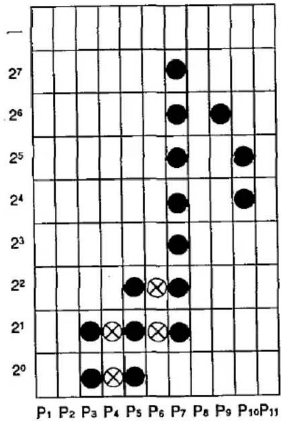
$$ \begin{array}{l} \mathrm{P} _ {1} = 0 \ \mathrm{P} _ {2} = 0 \ \mathrm{P} _ {3} = 3 \ \mathrm{P} _ {4} = 3 \ \mathrm{P} _ {5} = 7 \ \mathrm{P} _ {6} = 6 \ \mathrm{P} _ {7} = 2 5 4 \ \mathrm{P} _ {8} = 0 \ \mathrm{P} _ {9} = 6 4 \ \mathrm{P} _ {1 0} = 4 8 \ \mathrm{P} _ {\text {II}} = 0 \ \end{array} $$
Note: See page 5-7, 5th comment.
In our sample program lines 130\~170, therefore, use the eleven values P_i-P_ii (Program line 310 is data of P_i-P_ii ) to define the shape and size of the musical note using the upper 8 pins of the print head. Program lines 190–230 define the same shape and size, but for the lower 8 pins of the print head.
Next you must determine where in RAM the character(s) should be stored. The variables "Cs" and "Ce" are used for this purpose. The value specified for "Cs" indicates the ASCII location into which the starting downloaded character will be stored. The value specified for "Ce" indicates that ASCII location into which the ending downloaded character will be stored. If you are storing a single character, then Cs=Ce.
In our sample program, we created two musical note characters, one using the upper 8 pins of the print head, and the other using the lower 8 pins. These two distinct characters were stored in the ASCII locations where characters "A" and "B" are normally stored (see program line 110). Since "A" resides in ASCII location 65_DEC and "B" resides in ASCII location 66_DEC , the following program lines are equivalent.
110 LPRINT CHR\(27)+“&”+CHR\(0)+“AB”;
or
110 LPRINT CHR\(27) + “&” + CHR\(0) + CHR\(65) + CHR\(66);
Notice that Cs=65, Ce=66. Also note that CHR\(65)=“A” and CHR\(66)=“B”.
We must next define the value of "At", which specifies the attribute information.
The illustration below shows the role of each bit in the specification of the attribute information. Attribute information is stored in one byte.
| Bit NO. | Function | |
| MSB | 7 | Bit=1: use upper 8 pinsBit=0: use lower 8 pins |
| 6 | Derives print start (Ps) position | |
| 5 | for proportional spacing, | |
| 4 | 0≤Ps≤7 | |
| 3 | Derived print end (Pe) position | |
| 2 | for proportional spacing, | |
| 1 | 0≤Pe≤11 | |
| LSB | 0 | Ps |
Suppose we wish to create the character (musical note) in proportional spacing mode.
The values for Ps and Pe are derived from n and m (starting and ending print positions respectively) where Ps=n-1 and Pe=m-1. When printing characters from print column P_3 to P_11 in proportional spacing mode, Ps=2=(010)2 and Pe=10=(1010)2 . Thus, the attribute byte is as follows:
| Bit No. | Binary Form | Function |
| MSB 7 | 0 | Use lower 8 pins |
| 6 | 0 | Start of printing in column 3 (3-1) |
| 5 | 1 | |
| 4 | 0 | |
| 3 | 1 | End of printing in column 11 (11-1) |
| 2 | 0 | |
| 1 | 1 | |
| LSB 0 | 0 |
We then set "At" = 2^1 + 2^3 + 2^5 = 2 + 8 + 32 = 42
Comments:
- When you select an NLQ font (COURIER, PRESTIGE, BOLD PS) through the Control Table, the printer will print draft download characters in NLQ mode, see below for detail.
- The downloadable draft font actually consists of 12 columns of dots, but P_12 is always set to zero.
- Downloaded draft characters require 12 bytes per character:1 byte for attribute information and 11 bytes for the character design.
- Avoid continuous printing of download characters with high dot densities. 1 line has 8 pins × 11 columns × 80 character dots (7040 dots/line). Keep the line density to 25% of maximum (1760 dots/line).
In single height print mode, avoid using the same pin in two adjacent columns: otherwise, the pin in the second column of the pair will not be fired. In double height print mode, the musical note will print like the figure below. Pins will be fired in all the specified dot positions (● and ⊗) and the printer will add dots (○) automatically (see page 5-16, added dots for detailed information). If you select draft mode, specified dots (⊗) are not printed. However, you have to specify these dots (●) in order to print the character in double height mode or when NLQ is set from the Control Table.

scatter
| P | Black Circle | White Circle | |------|--------------|--------------| | P1 | 2^0 | 2^0 | | P2 | 2^1 | 2^1 | | P3 | 2^1 | 2^1 | | P4 | 2^1 | 2^1 | | P5 | 2^2 | 2^2 | | P6 | 2^2 | 2^2 | | P7 | 2^3 | 2^3 | | P8 | 2^4 | 2^4 | | P9 | 2^5 | 2^5 | | P10 | 2^5 | 2^5 | | P11 | 2^4 | 2^4 |NLQ FONT DOWNLOADING:
Defines near letter quality font.
Name: ESC+&+2+Cs+Ce+At+P 1H +P 1L +...+P _23L (0≤Cs≤Ce≤255)
Dec.: 27, 38, 2, Cs, Ce, At, P 1H , P 1L , ..., P _23L
Hex.: 1B, 26, 02, Cs, Ce, At, P 1H , P 1L , ..., P _23L
Input Format: LPRINT CHR\(27)+“&”+CHR\(2)+CHR\(Cs)+CHR\(Ce)+CHR\(At)+CHR\(P1R)+CHR\(P1L)+93+CHR\(P23L)
100 REM DEFINITION OF DOWNLOAD CHARACTERS IN NLQ MODE 101 WIDTH "LPT1:", 255 102 OPEN "LPT1:" AS #1 110 PRINT #1, CHR(27) + "&" + CHR(2) + CHR(65) + CHR(65); 120 REM STORE IN PLACE OF "A" - ASCII CODE 65 130 PRINT #1, CHR$(11); 140 RESTORE 260 150 FOR I=1 TO 23*2 160 READ A : PRINT #1, CHR$(A); 170 NEXT I 180 REM SELECT DOWNLOAD CHARACTER 190 PRINT #1, CHR(27) + "%"+ CHR(1); 200 PRINT #1, CHR$(27) + "x1"; 210 PRINT #1, "AAAAAAAAAAA"+ CHR(10) + CHR(10); 220 REM DOUBLE HEIGHT DOUBLE WIDTH PRINT 230 PRINT #1, CHR(27) + "W1"+ CHR(27) + "w1"; 240 PRINT #1, "AAAAAAAAAAA"+ CHR$(10); 241 CLOSE 250 END 260 DATA 0, 12, 0, 18, 0, 2, 0, 2, 15, 1, 16, 129, 32, 129, 64, 129 270 DATA 0, 129, 128, 129, 128, 129, 128, 129, 128, 129, 130 280 DATA 65, 130, 32, 242, 31, 12, 32, 0, 0, 0, 0, 0, 0, 0, 0,
$$ \begin{array}{c} 9 9 9 9 9 9 9 9 9 \ 9 9 9 9 9 9 9 9 9 9 \end{array} $$
Comment:
●This command is operational only when the 32k buffer option (KX-P43) is installed.
Explanation:
An NLQ font downloaded character uses 23 columns and 16 rows of dots. Since a given column contains 16 dots, each column is divided into 2 bytes. For example, column 1 is labeled PIH for the upper 8 dots and PIL for the lower 8 dots. Similarly, column 23 is labeled P23H for the upper 8 dots and P23L for the lower 8 dots. Column 24 is always set to zero; thus, we are working with PIH - P23H and PIL - P23L . Additionally, since each column contains 16 dots which overlap, the printing of an entire character is accomplished with two passes of the print head.

Then
| P_1H | =0 | P_13H | =128 | P_1L | =12 | P_13L | =129 |
| P_2H | =0 | P_14H | =128 | P_2L | =18 | P_14L | =130 |
| P_3H | =0 | P_15H | =65 | P_3L | =2 | P_15L | =130 |
| P_4H | =0 | P_16H | =32 | P_4L | =2 | P_16L | =242 |
| P_5H | =15 | P_17H | =31 | P_5L | =1 | P_17L | =12 |
| P_6H | =16 | P_18H | =32 | P_6L | =129 | P_18L | =0 |
| P_7H | =32 | P_19H | =0 | P_7L | =129 | P_19L | =0 |
| P_8H | =64 | P_20H | =0 | P_8L | =129 | P_20L | =0 |
| P_9H | =0 | P_21H | =0 | P_9L | =129 | P_21L | =0 |
| P_10H | =128 | P_22H | =0 | P_10L | =129 | P_22L | =0 |
| P_11H | =128 | P_23H | =0 | P_11L | =129 | P_23L | =0 |
| P_12H | =128 | P_12L | =129 |
Program lines 130\~170, therefore, use the values P_1H-P_23H and P_1L-P_23L to define the shape and size of the character using the lower 8 pins of the print head.
As shown in program line 110, this single character is stored in ASCII location 65, where the character "A" normally resides.
Downloading NLQ font characters requires 1 byte of attribute information which is input as the value of "At". Same as attribute information of draft font, refer to page 5-5 table.
The values Ps and Pe of NLQ attribute information are derived from n and m (starting and ending print positions respectively) using the equation Ps=(n-1)/2 and Pe=(m-1)/2. To ensure that Ps and Pe are integers, the character must be designed so that n and m are odd.
In this example, the g starts in column 1 and ends in column 23, and Ps=0=(000) 2 and Pe=11=(1011) 2 . Thus, the attribute byte is as follows:
| Bit No. | Binary Form | Function |
| MSB 7 | 0 | Use lower 8 pins |
| 6 | 0 | Start of printing in column 1 (1-1)/2 |
| 5 | 0 | |
| 4 | 0 | |
| 3 | 1 | End of printing in column 23 (23-1)/2 |
| 2 | 0 | |
| 1 | 1 | |
| LSB 0 | 1 |
We then set "At" = 2^3 + 2^1 + 2^0 = 8 + 2 + 1 = 11
Refer to program line 130.
Comments:
●Downloaded NLQ font characters require 47 bytes per character: 1 byte for attribute information and 46 bytes for the character design.
●Refer to comments for single height print mode on page 5-7.
ROM CHARACTER GENERATOR SET COPY:
Copies internal ROM CG font into downloadable font area.
Name: ESC+:+0+0+0
Dec.: 27,58,0,0,0
Hex.: 1B, 3A, 00, 00, 00
Input Format: LPRINT CHR\(27)+“:”+CHR\(0)+CHR\(0)+CHR\(0)
Example:
100 REM CHARACTER GENERATOR SELECTION
101 WIDTH "LFT1:", 255
102 OPEN "LFT1:" AS #1
110 REM ROM CG SET COPY TO DOWNLOAD BUFFER
120 PRINT #1, CHR(27)+": "+CHR(0)+CHR(0)+CHR(0);
130 REM DOWNLOAD TO "!" IN DRAFT FONT
140 PRINT #1, CHR(27)+"&"+CHR(0)+"!!";
150 PRINT #1, CHR$(11);
160 RESTORE 270
170 FOR I=1 TO 11
180 READ A: PRINT #1, CHR$(A);
190 NEXT I
200 REM SELECT DOWNLOAD CG
210 PRINT #1, CHR(27)+"%"+CHR(1);
220 PRINT #1, "SELECT DRAFT FONT DOWNLOAD CG !!!"+CHR$(10);
230 REM SELECT ROM CG
240 PRINT #1, CHR(27)+"%"+CHR(0);
250 PRINT #1, "SELECT DRAFT FONT ROM CG !!!"+CHR$(10);
251 CLOSE
260 END
270 DATA 0, 0, 3, 3, 7, 6, 254, 0, 64, 48, 0
SELECT DRAFT FONT DOWNLOAD CG !!! SELECT DRAFT FONT ROM CG !!!
Comments:
● All ROM CG font in draft and NLQ modes are copied to the downloadable font area.
● Usable capacity of downloadable font does not decrease by using ROM CG set copying.
●Upon receipt of the command, all previous downloaded font will be changed to ROM CG font. The usable capacity of downloadable font returns to the initial state.
- When altering only part of the ROM CG, use this command before font downloading.
CHARACTER GENERATOR SELECTION:
Selects the character generator.
Name: ESC+%+n
(n=0 or n=1)
Dec.: 27,37,n
Hex.: 1B, 25, n
Comment:
●“n” specifies the CG mode. n=0: Resident (internal) CG n=1: Download CG
IBM Mode
In IBM mode there are many methods of printing down line loaded characters. The various methods are shown in the table below:
| Print Method | Selection Command | Dot Columns |
| Draft Download | ESC+I+4 | 11 Max. |
| Draft Download 12 CPI High Speed | ESC+I+5 | 9 Max. |
| Text Download fonts | ESC+I+6 | 11 Max.* |
| NLQ Download fonts | ESC+I+7 | 23** (Prints same space as columns) |
* Text download fonts are derived from a Draft download matrix (the printer adds dots to create NLQ characters). Proportional spacing is supported.
** NLQ fonts print as designed (the printer does not add dots). Proportional spacing is not supported.
Draft and Text Character Downloading
Name: ESC+=+n_1+n_2+20+Cs+At_1+At_2+P_1+P_2++P_11 (0≤Cs≤255)
Dec.: 27, 61, n₁, n₂, 20, Cs, At₁, At₂, P₁, P₂, ..., P₁
Hex.: 1B, 3D, n₁, n₂, 14, Cs, At₁, At₂, P₁, P₂, ..., P₁
n_1,n_2 indicate the number of bytes of character data to be loaded.
Total count=(total characters×13)+2 and n₂=integer portion of total count/256 and n₁=remainder.
For example, to find n_1 and n_2 for 32 characters:
Total count=(32×13)+2=418
$$ \begin{array}{r} 1 \ 2 5 6 \overline {{) 4 1 8}} \ \underline {{2 5 6}} \ 1 6 2 \end{array} $$
n_1=162, n_2=1
Note:
- If n_1 = n_2 = 0 all download characters are cleared.
●20 is a fixed number.
"Cs" indicates the first character position for loading characters. For example to load a character into the position occupied by the ASCII character "A", Cs=65
At _1 is attribute byte 1
Attribute byte 1 specifies:
Bit
| 7 | 0 - Print using upper 8 pins1 - Print using lower 8 pins |
| 6-2 | Ignored |
| 1,0 | 00 - Normal character01 - Line drawing character. The printer repeats the dots of row 8 in rows 9 to 12 as shown in Figure 1 on page 5-15.10 - Shading character. The dots in rows 1 to 4 are repeated in rows 9 to 12 as shown in Figure 2 on page 5-15. NLQ mode is ignored11 - Not supported |
Note:
● Bit 7 of attribute byte 1 is effective only if bits 0, 1 are 00.
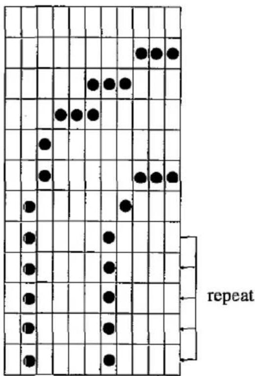
Figure 1
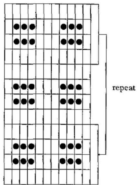
Figure 2
Attribute byte 2 specifies proportional spacing information about the character:
Bit
| 7 | Reserved |
| 6-4 | Specifies the number of column data bytes to ignore (up to 7 leading columns can be ignored). |
| 3-0 | Specifies the total number of dot column to be printed. Each character includes a blank column which must be printed. This column is not included by bits 3-0, e.g. For a character 10 columns wide (9 printable+1 blank) bits 3-0 would be 1001. Widths specified greater than 11 are truncated to 11. |
Note: To print all 11 columns, bits 6-0 may be set to 0.
Designing Draft and Text download characters.
When designing characters to print in both Draft and Text you should consider how the printer adds dots to create NLQ characters. The figures that follow show how the printer treats various situations. Black dots shown must be specified by the font design. Open circles represent dots that are automatically added by the printer in NLQ mode. Note horizontally adjacent dots specified in the font design do not print in draft mode.
Figure 1 illustrates how dots are added to vertical lines and how intersection of vertical and diagonal lines are treated. Figure 2 shows the intersection of two diagonal lines.

scatter
| Position | Black Dot Value | White Circle Value | |---|---|---| | P1 | 27 | 26 | | P2 | 26 | 25 | | P3 | 25 | 24 | | P4 | 24 | 23 | | Ps | 23 | 22 | | Ps | 22 | 21 | | P7 | 21 | 20 | | P8 | 20 | 19 | | P9 | 20 | 18 | | P10 | 20 | 17 | | P11 | 20 | 16 |Figure 1

scatter
| Position | Value | |---|---| | P1 | 27 | | P2 | 26 | | P3 | 25 | | P4 | 24 | | P5 | 23 | | P6 | 22 | | P7 | 21 | | P8 | 20 | | P9 | 19 | | P10 | 27 | | P11 | 26 |Figure 2
Figure 3 an example of the intersection of vertical and horizontal lines.

scatter
| X-axis | Y-axis | |---|---| | P1 | 27 | | P2 | 26 | | P3 | 25 | | P4 | 25 | | P5 | 24 | | P6 | 24 | | P7 | 23 | | P8 | 23 | | P9 | 22 | | P10 | 21 | | P11 | 20 |Figure 3
5-16 KX-P1170 Features
The intersection of diagonal and horizontal lines is printed out as two vertical dots, as shown in Figure 4.

scatter
| Point | X | Y | |---|---|---| | P1 | 27 | 27 | | P2 | 27 | 27 | | P3 | 27 | 21 | | P4 | 27 | 22 | | P5 | 27 | 23 | | P6 | 27 | 24 | | P7 | 27 | 25 | | P8 | 27 | 26 | | P9 | 27 | 27 | | P10 | 27 | 27 | | P11 | 27 | 27 |Figure 4
When you add the dots on a diagonal line, you can select the position of added dots as shown below.

scatter
| Point | X-axis | Y-axis | |---|---|---| | P1 | 2 | 27 | | P2 | 2 | 26.5 | | P3 | 2 | 26 | | P4 | 2 | 25.5 | | P5 | 2 | 22 | | P6 | 2 | 22.5 | | P7 | 2 | 23 | | P8 | 2 | 23.5 | | P9 | 2 | 24 | | P10 | 2 | 24.5 | | P11 | 2 | 20 | The chart displays a grid with values ranging from 20 to 27. Black and white circles represent two distinct data series. The x-axis labels are 'P1' through 'P11', and the y-axis labels are unlabeled but implied by the vertical alignment.Figure 5
As an example we will provide a basic program that loads and print in draft mode, the greek gamma character shown below.

scatter
| P | 20 | 21 | 22 | 23 | 24 | 25 | 26 | 27 | |-----|------|------|------|------|------|------|------|------| | P1 | | | | | | | | | | P2 | | | | | | | | | | P3 | | | | | | | | | | P4 | | | | | | | | | | P5 | | | | | | | | | | P6 | | | | | | | | | | P7 | | | | | | | | | | P8 | | | | | | | | | | P9 | | | | | | | | | | P10 | | | | | | | | | | P11 | | | | | | | | |P_1=0
P_2 = 2^2 + 2^3 = 4 + 8 = 12
P_3 = 2^1 +2^4 +2^7 = 2 + 16 + 128 = 146
P_4=2^0+2^=1+64=65
P_5=2^1+2^5=2+32=34
P_6 = 2^2 +2^3 +2^4 = 4 + 8 + 16 = 28
P_7 = 2^6 = 64
P_s = 0
P_9 = 2^7 = 128
P_10=0
P_11=0
Example
100 REM DRAFT DOWNLOAD CHARACTER
101 WIDTH "LPT1:", 255
102 OPEN "LPT1:" AS #1
110 PRINT #1, CHR(27) + "=" + CHR(15) + CHR(0) + CHR(20) + "A";
120 PRINT #1, CHR(0) + CHR(11);
130 RESTORE 240
140 FOR I = 1 TO 11
150 READ A : PRINT #1, CHR$(A);
160 NEXT I
170 REM PRINT DRAFT DOWNLOAD
180 PRINT #1, CHR(27) + "I" + CHR(4);
190 PRINT #1, "A A A A A" + CHR(10) + CHR(13);
200 REM PRINT TEXT DOWNLOAD
210 PRINT #1, CHR(27) + "I" + CHR(6);
220 PRINT #1, "A A A A A" + CHR(10) + CHR(13);
221 CLOSE
230 END
240 DATA 0, 12, 146, 65, 34, 28, 64, 0, 128, 0, 0
♂♂♂♂♂
NLQ FONT DOWNLOADING
Defines near letter quality font.
Name: ESC + = +n1 + n2 + 21 + Cs + At1 + At2 + P1H + P1L + +P_23L (0≤ Cs≤ 255)
Dec.: 27, 61, n1, n2, 21, Cs, At1, At2, P1H, P2L, ..., P23L
Hex.: 1B, 3D, n₁, n₂, 15, Cs, At₁, At₂, P₁H, P₂L, ..., P₂₃L
Input Format: LPRINT CHR\(27) + “=” + CHR\(n1) + CHR\(n2) + CHR\(21) + CHR\(Cs) + CHR\(At1) + CHR\(At2) + CHR\(P18) + CHR\(P2L) + ... + CHR\(P23L);
Example
100 REM NLQ DOWNLOAD CHARACTER
101 WIDTH "LPT1:", 255
102 OPEN "LPT1:" AS #1
110 PRINT #1, CHR(27) + "=" + CHR(50) + CHR(0) + CHR(21) + "A";
120 PRINT #1, CHR(0) + CHR(11);
130 RESTORE 210
140 FOR I=1 TO 23*2
150 READ A : PRINT #1, CHR$(A);
160 NEXT I
170 REM PRINT NLQ DOWNLOAD
180 PRINT #1, CHR(27) + "I" + CHR(7);
190 PRINT #1, "A A A A A" + CHR(10) + CHR(13);
191 CLOSE
200 END
210 DATA 2, 2, 1, 4, 1, 0, 1, 0, 48, 49, 8, 65, 72, 1, 8, 129
220 DATA 8, 1, 136, 1, 136, 1, 136, 1, 136, 1, 137, 0, 9, 144
230 DATA 77, 12, 50, 114, 64, 0, 0, 0, 0, 0, 0, 0, 0, 0
9 9 9 9 9
Explanation:
An NLQ font download character uses 23 columns and 18 rows of dots. Column 24 is always blank. PH specifies the contents of odd rows, PL the even rows. Of the 18 rows of dots available for each character, only 16 can be printed for normal characters (not line draw or shading). If bit 7 of attribute byte 1 is 0, rows 1\~16 will print; if it is set to 1, rows 3\~18 will print.
NLQ font Downloading

scatter
| X | Y | |---|---| | 2 | 2 | | 4 | 0 | | 48 | 49 | | 65 | 1 | | 72 | 129 | | 8 | 1 | | 136 | 1 | | 136 | 1 | | 136 | 1 | | 136 | 1 | | 137 | 0 | | 9 | 144 | | 77 | 12 | | 50 | 114 | | 64 | 0 | | 0 | 0 | | 0 | 0 | | 0 | 0 | | 0 | 0 | | 0 | 0 | | 0 | 0 | | 0 | 0 | | 0 | 0 | | 0 | 0 | | 0 | 0 | | 0 | 0 | | 0 | 0 | | 0 | 0 | | 0 | 0 | | 0 | -17 | | 15 | -17 | | 15 | -16 | | 15 | -15 | | 15 | -14 | | 15 | -13 | | 15 | -12 | | 15 | -11 | | 15 | -10 | | 15 | -9 | | 15 | -8 | | 15 | -7 | | 15 | -6 | | 15 | -5 | | 15 | -4 | | 15 | -3 | | 15 | -2 | | 15 | -1 | | 15 | 0 | | 15 | -2 | | 15 | -3 | | 15 | -4 | | 15 | -5 | | 15 | -6 | | 15 | -7 | | 15 | -8 | | 15 | -9 | | 15 | -10 | | 15 | -11 | | 15 | -12 | | 15 | -13 | | 15 | -14 | | 15 | -15 | | 15 | -16 | | 15 | -17 | | 17 | -17 | | 48 | -49 | | 65 | -49 | | 72 | -49 | | 8 | -49 | | 8 | -48 | | 8 | -47 | | 8 | -46 | | 8 | -45 | | 8 | -44 | | 8 | -43 | | 8 | -42 | | 8 | -41 | | 8 | -40 | | 8 | -39 | | 8 | -38 | | 8 | -37 | | 8 | -36 | | 8 | -35 | | 8 | -34 | | 8 | -33 | | 8 | -32 | | 8 | -31 | | 8 | -30 | | 8 | -29 | | 8 | -28 | | 8 | -27 | | 8 | -26 | | 8 | -25 | | 8 | -24 | | 8 | -23 | | 8 | -22 | | 8 | -21 | | 8 | -20 | | 8 | -19 | | 8 | -18 | | 8 | -17 | | 8 | -16 | | 8 | -15 | | 8 | -14 | | 8 | -13 | | 8 | -12 | | 8 | -11 | | 8 | -10 | | 8 | -9 | | 8 | -8 | | 8 | -7 | | 8 | -6 | | 8 | -5 | | 8 | -4 | | 8 | -3 | | 8 | -2 | | 8 | -1 | | 8 | 0 | | 8 | -2 | | 8 | -3 | | 8 | -4 | | 8 | -5 | | 8 | -6 | | 8 | -7 | | 8 | -8 | | 8 | -9 | | 8 | -10 | | 8 | -11 | | 8 | -12 | | 8 | -13 | | 8 | -14 | | 8 | -15 | | 8 | -16 | | | ... (plotted) for the grid is filled with 'P' and 'P', but the values are not explicitly labeled in the image.NLQ downloading characters require 48 bytes per character. There are 2 bytes attribute information and 46 bytes for the character design.
Attribute information 1
| Bit NO. | Function |
| 7 | 0 - Normal character1 - Descending character |
| 6-2 | Ignored |
| 1,1 | 00 - Normal character print mode(no block graphic character)01 - Line-drawing characterThe printer repeats the dots of row 15 in 17, 19, 21 and 23, row 16 in 18, 20, 22 and 24.11 - Shading characterThe printer repeats the dots of row 1, 3, 5 and 7 on 17, 19, 21 and 23, row 2, 4, 6 and 8 on 18, 20, 22 and 24.11 - Not supported |
Attribute information 2 is reserved. Always set attribute 2 to zero.
5.3 Bit Image (Graphics)
The bit image (graphics) mode enables you to control the firing of each pin of the print head to create virtually any graphics design you desire.
Dot per inch density (dot resolution) refers to the number of dots which can be printed horizontally. This printer enables you to access a variety of dot densities through specific control commands. The various dot densities and corresponding control commands appear in table below.
| Command | Function | Dot Density |
| ESC+K+n_1+n_2 | Standard density designation | 60 |
| ESC+L+n_1+n_2 | Double density designation | 120 |
| ESC+Y+n_1+n_2 | Double speed, double density designation | 120 |
| ESC+Z+n_1+n_2 | Quadruple density designation | 240 |
| ESC^**+m+n_1+n_2 (Standard Mode only) | 8-Pin Mode Selection: | |
| m=0 (Standard) | 60 | |
| m=1 (Double) | 120 | |
| m=2 (Double speed, double density) | 120 | |
| m=3 (Quadruple density) | 240 | |
| m=4 | 80 | |
| m=5 | 72 | |
| m=6 | 90 | |
| m=7 | 144 | |
| ESC^+^+m+n_1+n_2 (Standard Mode only) | 9-Pin Mode Selection: | |
| m=0 (Standard) | 60 | |
| m=1 (Double) | 120 | |
| m=2 (Double speed, double density) | 120 | |
| m=3 (Quadruple density) | 240 | |
| m=4 | 80 | |
| m=5 | 72 | |
| m=6 | 90 |
Dot Resolution (Dots per inch)
| Command | Function | Dot Density |
| ESC+?+n+m(Standard mode only) | Bit Image Mode Reassignment:n="K", "L", "Y", "Z"m=0 (Standard)m=1 (Double)m=2 (Double speed, double density)m=3 (Quadruple density)m=4m=5m=6m=7 | 60120120240807290144 |
Dot Resolution (Dots per inch)
As you can see, each graphics control command uses two bytes, n1, and n2, for the designation of the actual number of dots you want printed on a line. The data entered in your program must match this dot specification; if not, in all likelihood your graphics data will contain strange characters.
Determining the values of n_1 , and n_2 can be accomplished in the following way. Assume that you want to print N dots on a line, where N is within the proper range for the dot density. Then the outcome of the division below yields the values n_1 and n_2 .
$$ 2 5 6 \sqrt {\frac {n _ {2}}{N}} \frac {- 2 5 6 \times n _ {2}}{n _ {1}} $$
Where n_2 is the integer quotient and n_1 is the remainder. For those users with a BASIC programming background, n_2=INT(N/256) and n_1=N-(256*n_2) .
As an example, suppose we want to print 967 dots per line. Then:
$$ \begin{array}{r l} {2 5 6 \sqrt {\frac {3}{9 6 7}}} \ {\frac {7 6 8}{1 9 9}} \end{array} , \text { so } n _ {2} = 3 \text { and } n _ {1} = 1 9 9 $$
5-22 KX-P1170 Features
8-Pin Bit Image Mode
Of the 9 pins in the print head, the 8-pin bit image graphics mode uses the upper eight pins only. Each pin corresponds to a power of two. By summing the powers of two corresponding to each of the pins you wish to fire, you will obtain a numerical value which instructs the printer to print one column of dots. Through such techniques in BASIC as looping, numerical values for each column on a line are input and processed. The result is one line of graphics.
| Pin No. | Pins | 8-Bit Interface | 7-Bit Interface |
| 1 | 2^7=128 | Not used | |
| 2 | 2^6=64 | 2^6=64 | |
| 3 | 2^5=32 | 2^5=32 | |
| 4 | 2^4=16 | 2^4=16 | |
| 5 | 2^3=8 | 2^3=8 | |
| 6 | 2^2=4 | 2^2=4 | |
| 7 | 2^1=2 | 2^1=2 | |
| 8 | 2^0=1 | 2^0=1 | |
| 9 | Not used | Not used |
As an example, suppose you want to fire pins 1, 2, 5 and 8 simultaneously. Then you compute the following sum:
$$ \begin{array}{l} \text { Input Code } = \text { Pin 1 Code } + \text { Pin 2 Code } + \text { Pin 5 Code } + \text { Pin 8 Code } \ = 2 ^ {7} + 2 ^ {5} + 2 ^ {3} + 2 ^ {0} \ = 1 2 8 + 6 4 + 8 + 1 \ = 2 0 1 \ \end{array} $$
Thus, the value 201 is entered in the CHR\$ function in order to print a single column of dots resulting from firing pins 1, 2, 5 and 8.
For our final example, refer to the standard density designation in the table on page 5-21. This setting is given by ESC+K+n₁+n₂. Suppose you wish to print 100 columns of dots, where every column fires pins 1 and 8 only.
$$ \begin{array}{r l} 2 5 6 \sqrt {\frac {0}{1 0 0}} & \ \frac {0}{1 0 0} & , \text { so } n _ {2} = 0 \text { and } n _ {1} = 1 0 0 \end{array} $$
You first compute the values of n_1 and n_2 .
Our control code ESC+K+n1+n2 now translates into:
$$ \text { LPRINT CHR } (2 7) + \text {"K"} + \text { CHR } (1 0 0) + \text { CHR } (0); $$
Next compute the code for firing pins 1 and 8 simultaneously:
$$ \begin{array}{l} \text { Input Code } = \text { Pin 1 Code } + \text { Pin 8 Code } \ = 2 ^ {7} + 2 ^ {0} \ = 1 2 8 + 1 \ = 1 2 9 \ \end{array} $$
Finally, we incorporate our two calculations into the following program. Note that lines 20 and 30 are necessary for the proper execution of this program on many IBM-compatible computers.
Such BASIC statements suppress CR and LF codes and enable printing on a full line without unwanted "breaks". Programs which include statements such as lines 20 and 30 cannot use LPRINTs to print data. In such cases, PRINT# statements must be used. Line 90 is necessary to CLOSE all open files.
10 REM STANDARD DENSITY
20 WIDTH "LPT1:", 255
30 OPEN "LPT1:" AS #1
40 PRINT #1, CHR(27) + "K" + CHR(100) + CHR$(0);
50 FOR I = 1 TO 100
60 PRINT #1, CHR$(129);
70 NEXT I
80 PRINT #1, CHR$(10);
90 CLOSE
100 END
9-Pin Bit Image Mode (Standard Mode only)
In the 9-pin bit image mode, all 9 pins of the printed head may be fired. The 9 pins in the print head are divided into two portions, the upper 8 pins and the bottom pin.
As in the 8-pin mode, the upper 8 pins correspond to powers of two, ranging from 2^0 to 2^7 . The firing of one or more of these 8 pins represents 1 bytes of data. The 9th (bottom-most) pin represents an additional byte of data. When fired, it is represented by the value 2^7 . When not fired, it is represented by the value 0. Together, these two bytes determine the dot configuration for a single column of graphics.
| Pin No. | Pins | Interface | Byte |
| 1 | • | 2^7=128 | |
| 2 | • | 2^6=64 | |
| 3 | • | 2^5=32 | |
| 4 | • | 2^4=16 | 1 |
| 5 | • | 2^3=8 | |
| 6 | • | 2^2=4 | |
| 7 | • | 2^1=2 | |
| 8 | • | 2^0=1 | |
| 9 | • | 2^7=128 | |
| NOTUSED | 2 |
As an example, suppose you want to fire pins 1, 2, 5, 8 and 9 simultaneously. Then you determine the following two values:
$$ \begin{array}{l} \text { Pin 8 Code } \ = 2 ^ {7} + 2 ^ {6} + 2 ^ {3} + 2 ^ {0} \ = 1 2 8 + 6 4 + 8 + 1 \ = 2 0 1 \ \end{array} $$
Byte 1: Input Code = Pin 1 Code + Pin 2 Code + Pin 5 Code +
(n)
Byte 2: Input Code = Pin 9 Code
(n_2)
$$ = 2 ^ {7} $$
$$ = 1 2 8 $$
Thus, the two bytes for a single column of dots are entered as: CHR\(201); CHR\(128);
Refer to the 9-pin standard density designation in the table on page 5-21. This setting is given by ESC+ ^+ +m+n 1 +n 2 , where m=0. Suppose you wish to print 100 columns of dots, where every column fires pins 1, 2, 5, 8 and 9 as above.
As in the 8-pin example on page 5-24, n_1 = 100 and n_2 = 0 . Our control code ESC + ^ + m + n_1 + n_2 now translates into:
$$ \text { LPRINT CHR } (2 7) + ^ {\prime \prime} + \text { CHR } (0) + \text { CHR } (1 0 0) + \text { CHR } (0); $$
If we incorporate this information into a program, we might have the following:
10 REM 9-PIN STANDARD DENSITY
20 WIDTH "LPT1:", 255
30 OPEN "LPT1:" AS #1
40 PRINT #1, CHR(27) + "^"+CHR(0) + CHR(100) + CHR(0);
50 FOR I = 1 TO 100
60 PRINT #1, CHR(201) + CHR(128);
70 NEXT I
80 PRINT #1, CHR$(10);
90 CLOSE
100 END
6. Software Commands
This chapter covers the software commands for Standard and IBM Mode. The software commands are grouped into the following classifications:
Standard Mode (FX-86e/FX-800)
FONT SELECTION
| Name | Function | Page |
| ESC+4 | Selects Italic printing | 6-10 |
| ESC+5 | Releases Italic printing | 6-10 |
| ESC+k+n | Selects Print font style | 6-10 |
| ESC+x+1 | Selects NLQ font | 6-11 |
| ESC+x+0 | Releases NLQ font | 6-11 |
| ESC+S+1 | Selects subscript printing | 6-12 |
| ESC+S+0 | Selects superscript printing | 6-12 |
| ESC+T | Releases sub/superscript printing | 6-12 |
CHARACTER PITCH SELECTION
| Name | Function | Page |
| ESC+P | Sets 10 cpi (pica pitch) printing | 6-12 |
| ESC+M | * Sets 12 cpi (elite pitch) printing | 6-13 |
| ESC+g | Sets 15 cpi (Micron) printing | 6-13 |
| SI | * Sets 17 cpi (compressed) printing | 6-14 |
| ESC+SI | * Sets 17 cpi (compressed) printing | 6-14 |
| DC2 | Releases compressed printing | 6-14 |
| ESC+p+1 | Sets proportional spacing | 6-14 |
| ESC+p+0 | Releases proportional spacing | 6-14 |
| ESC+SP+n | Sets character dot spacing | 6-15 |
| ESC+!+n | Sets certain pitches based upon value of n | 6-15 |
CHARACTER HIGHLIGHT SELECTION
| Name | Function | Page |
| ESC+!+n | Sets highlighting based upon value of n | 6-15 |
| ESC+E | Sets emphasized printing | 6-16 |
| ESC+F | Releases emphasized printing | 6-16 |
| ESC+G | Sets double printing | 6-16 |
| ESC+H | Releases double printing | 6-16 |
* When 12 cpi and compressed pitch are set simultaneously, subsequent output is printed in 20 cpi (160 characters per line).
| SO | Sets single-line double width printing | 6-17 |
| DC4 | Releases single-line double width printing | 6-17 |
| ESC+SO | Sets single-line double width printing | 6-17 |
| ESC+W+1 | Sets double width printing | 6-17 |
| ESC+W+0 | Releases double width printing | 6-17 |
| ESC+w+1 | Sets double-high printing | 6-17 |
| ESC+w+0 | Releases double-high printing | 6-17 |
| ESC+ - +1 | Sets underlining | 6-18 |
| ESC+ - +0 | Releases underlining | 6-18 |
CHARACTER SET SELECTION
| Name | Function | Page |
| ESC+R+n | Sets international character set | 6-19 |
| ESC+6 | Selects IBM Character Set II | 6-20 |
| ESC+7 | Selects IBM Character Set I | 6-20 |
| ESC+t+n | Selects alternate character set | 6-21 |
BIT IMAGE (GRAPHICS) MODE SELECTION
| Name | Function | Page |
| ESC+K+n_1+n_2 | Sets standard density (480 dot/line) | 6-22 |
| ESC+L+n_1+n_2 | Sets double density (960 dot/line) | 6-22 |
| ESC+Y+n_1+n_2 | Sets double density/double speed(960 dot/line) | 6-22 |
| ESC+Z+n_1+n_2 | Sets quadruple density (1920 dot/line) | 6-22 |
| ESC+*+m+n_1+n_2 | Sets 8-pin bit image mode selection(480, 576, 640, 720, 960, 1152, 1920) | 6-23 |
| ESC+^+m+n_1+n_2 | Sets 9-pin bit image mode selection(480, 576, 640, 720, 960, 1152, 1920) | 6-23 |
| ESC+?+n+m | Reassigns graphics mode density | 6-24 |
PAPER FEED SELECTION — Amount
| Name | Function | Page |
| ESC+0 | Sets paper feed to 1/8 inch (3.2 mm) | 6-24 |
| ESC+1 | Sets paper feed to 7/72 inch (2.47 mm) | 6-25 |
| ESC+2 | Sets paper feed to 1/6 inch (4.2 mm) | 6-25 |
| ESC+A+n | Sets paper feed to n/72 | 6-25 |
| ESC+3+n | Sets paper feed to n/216 inch | 6-26 |

PAPER FEED SELECTION — Execution
| Name | Function | Page |
| FF | Feeds paper to next top form position | 6-27 |
| LF | Feeds paper one line | 6-27 |
| ESC+J+n | Executes one-line paper feed of n/216 inch | 6-28 |
| ESC+j+n | Executes one-line reverse paper feed of n/216 inch | 6-28 |
PAGE FORMAT CONTROL
| Name | Function | Page |
| ESC+C+0+n | Sets page length in inches | 6-29 |
| ESC+C+n | Sets page length in lines | 6-30 |
| ESC+Q+n | Sets right margin | 6-30 |
| ESC+l+n | Sets left margin | 6-31 |
| ESC+a+0 | Enables left alignment | 6-32 |
| ESC+a+1 | Enables auto centering | 6-32 |
| ESC+a+2 | Enables right alignment | 6-32 |
| ESC+a+3 | Enables auto justification | 6-33 |
| ESC+N+n | Sets skip perforation | 6-34 |
| ESC+O | Releases skip perforation | 6-34 |
TABULATION — Horizontal
| Name | Function | Page |
| ESC+D+n_1+...+n_x+0 | Sets horizontal tab | 6-34 |
| ESC+D+0 | Releases horizontal tab | 6-34 |
| HT | Executes horizontal tab | 6-35 |
TABULATION — Vertical
| Name | Function | Page |
| ESC+B+n_1+...+n_x+0 | Sets vertical tab | 6-35 |
| ESC+B+0 | Releases vertical tab | 6-35 |
| VT | Executes vertical tab | 6-36 |
| ESC+/+n | Sets VFU channel | 6-36 |
| ESC+b+m+n_1+...+n_x+0 | Sets VFU tabulation | 6-37 |
| ESC+b+m+0 | Releases VFU tabulation | 6-37 |
CARRIAGE CONTROL
| Name | Function | Page |
| BS | Prints, then backspaces one character | 6-37 |
| CR | Prints a line, then returns carriage | 6-38 |
| ESC+< | Sets one line unidirection print | 6-38 |
| ESC+U+1 | Sets single direction printing | 6-38 |
| ESC+U+0 | Releases single direction printing | 6-38 |
| ESC+s+1 | Sets half speed printing | 6-39 |
| ESC+s+0 | Releases half speed printing | 6-39 |
| ESC+\n1+n2 | Moves the printhead to a relative horizontal position | 6-39 |
| ESC+$n1+n2 | Moves the printhead to an absolute horizontal position | 6-40 |

DATA CONTROL
| Name | Function | Page |
| CAN | Clears data in buffer | 6-40 |
| DC1 | Selects printer remotely | 6-40 |
| DC3 | Deselects printer remotely | 6-41 |
| DEL | Deletes last printable character | 6-41 |
| ESC+> | Sets MSB on | 6-42 |
| ESC+= | Sets MSB off | 6-42 |
| ESC+# | Cancels MSB setting | 6-42 |
| ESC+I+1 | Selects undefined code printing | 6-43 |
| ESC+I+0 | Releases printing code from undefined code location | 6-43 |
DOWNLOADABLE CHARACTER SELECTION
| Name | Function | Page |
| ESC+ \& +0+Cs+Ce+At+P_1+P_2+...+P_11 | Defines download draft font | 6-44 |
| ESC+ \& +2+Cs+Ce+At+P_1H+P_1L+...+P_23L | Defines download near letter quality font | 6-44 |
| ESC+%+n | Selects download CG | 6-44 |
| ESC+:+0+0+0 | Copies internal CG font intodownload CG | 6-45 |
MISCELLANEOUS
| Name | Function | Page |
| ESC | First byte of multi-byte control codes | 6-45 |
| NUL | Last byte of certain multi-byte control codes | 6-46 |
| ESC+@ | Initializes the printer | 6-46 |
| ESC+9 | Enables paper-out detection | 6-46 |
| ESC+8 | Disables paper-out detection | 6-46 |
| ESC+EM+n | Selects Cut Sheet Feeder | 6-47 |
IBM Mode (Proprinter II)
FONT SELECTION
| Name | Function | Page |
| ESC+k+n | Selects NLQ font | 6-10 |
| ESC+I+n | Selects font | 6-11 |
| ESC+G | Sets double strike printing | 6-12 |
| ESC+H | Releases double strike printing | 6-12 |
| ESC+S+1 | Selects subscript printing | 6-12 |
| ESC+S+0 | Selects superscript printing | 6-12 |
| ESC+T | Releases sub/superscript printing | 6-12 |
CHARACTER PITCH SELECTION
| Name | Function | Page |
| ESC+: | Sets 12 cpi (elite pitch) printing | 6-13 |
| SI | Sets 17 cpi (compressed) printing | 6-14 |
| ESC+SI | Sets 17 cpi (compressed) printing | 6-14 |
| DC2 | Releases elite and compressed printing | 6-14 |
| ESC+P+1 | Sets proportional spacing | 6-15 |
| ESC+P+0 | Releases proportional spacing | 6-15 |
CHARACTER HIGHLIGHT SELECTION
| Name | Function | Page |
| ESC+E | Sets emphasized printing | 6-16 |
| ESC+F | Releases emphasized printing | 6-16 |
| SO | Sets single-line double width printing | 6-17 |
| DC4 | Releases single-line double width printing | 6-17 |
| ESC+SO | Sets single-line double width printing | 6-17 |
| ESC+W+1 | Sets double width printing | 6-17 |
| ESC+W+0 | Releases double width printing | 6-17 |
| ESC+[+@+n1+n2+m1+m2+m3+m4 | Sets double-high printing | 6-18 |
| ESC+-+1 | Sets underlining | 6-18 |
| ESC+-+0 | Releases underlining | 6-18 |
| ESC+_+1 | Sets overlining | 6-19 |
| ESC+_+0 | Releases overlining | 6-19 |

CHARACTER SET SELECTION
| Name | Function | Page |
| ESC+6 | Selects IBM Character Set II | 6-20 |
| ESC+7 | Selects IBM Character Set I | 6-20 |
| ESC+ n_1 + n_2 | Sets all character set (Continuous) | 6-21 |
| ESC+ ^ | Sets all character set (Single) | 6-21 |
BIT IMAGE (GRAPHICS) MODE SELECTION
| Name | Function | Page |
| ESC+K+n_1+n_2 | Sets standard density (480 dot/line) | 6-22 |
| ESC+L+n_1+n_2 | Sets double density (960 dot/line) | 6-22 |
| ESC+Y+n_1+n_2 | Sets double density/double speed(960 dot/line) | 6-22 |
| ESC+Z+n_1+n_2 | Sets quadruple density (1920 dot/line) | 6-22 |
PAPER FEED SELECTION — Amount
| Name | Function | Page |
| ESC+0 | Sets paper feed to 1/8 inch (3.2 mm) | 6-24 |
| ESC+1 | Sets paper feed to 7/72 inch (2.47 mm) | 6-25 |
| ESC+2 | Executes line spacing set by ESC+A | 6-25 |
| ESC+A+n | Sets paper feed to n/72 | 6-25 |
| ESC+3+n | Sets paper feed to n/216 inch | 6-26 |
| ESC+5+1 | Sets automatic line feed on | 6-26 |
| ESC+5+0 | Sets automatic line feed off | 6-26 |
PAPER FEED SELECTION — Execution
| Name | Function | Page |
| FF | Feeds paper to next top of form position | 6-27 |
| LF | Feeds paper one line | 6-27 |
| ESC+J+n | Executes one-line paper feed of n/216 inch | 6-28 |
PAGE FORMAT CONTROL
| Name | Function | Page |
| ESC+C+0+n | Sets page length in inches | 6-29 |
| ESC+C+n | Sets page length in lines | 6-30 |
| ESC+X+n1+n2 | Sets left and right margin | 6-31 |
| ESC+4 | Sets top of form | 6-33 |
| ESC+N+n | Sets skip perforation | 6-34 |
| ESC+O | Releases skip perforation | 6-34 |
TABULATION — Horizontal
| Name | Function | Page |
| ESC+D+n1+...+n2+0 | Sets horizontal tab | 6-34 |
| ESC+D+0 | Releases horizontal tab | 6-34 |
| HT | Executes horizontal tab | 6-35 |
TABULATION — Vertical
| Name | Function | Page |
| ESC+B+n1+...+n3+0 | Sets vertical tab | 6-35 |
| ESC+B+0 | Releases vertical tab | 6-35 |
| VT | Executes vertical tab | 6-36 |
| ESC+R | Returns to default tabs | 6-36 |
CARRIAGE CONTROL
| Name | Function | Page |
| BS | Prints, then backspaces one character | 6-37 |
| CR | Prints a line, then returns carriage | 6-38 |
| ESC+U+1 | Sets single direction printing | 6-38 |
| ESC+U+0. | Releases single direction printing | 6-38 |
DATA CONTROL
| Name | Function | Page |
| CAN | Clears data in buffer | 6-40 |
| DC1 | Selects printer remotely | 6-40 |
| ESC+Q+3 | Deselects printer remotely | 6-41 |
DOWNLOADABLE CHARACTER SELECTION
| Name | Function | Page |
| ESC+ = +n_1 + n_2 | Defines download draft font | 6-45 |
MISCELLANEOUS
| Name | Function | Page |
| ESC | First byte of multi-byte control codes | 6-45 |
| NUL | Last byte of certain multi-byte control codes | 6-46 |
| ESC+9 | Enables paper-out detection | 6-46 |
| ESC+8 | Disables paper-out detection | 6-46 |
ITALIC FONT:
(Standard Mode only)
Selects italic character printing.
Name: Set: ESC+4
Release: ESC+5
Dec.: 27,52
27,53
Hex.: 1B,34
1B, 35
Comment:
- Italic characters in locations 160_DEC - 254_DEC (A0HEX-FEHEX) are printed in place of characters in locations 32_DEC - 126_DEC (20HEX-7EHEX).
NLQ FONT STYLE:
Selects NLQ font style.
Name: ESC+k+n
(n=0, 1, 2, 3, 6)
Dec.: 27,107,n
Hex.: 1B, 6B, n
Comments:
●The following values can be used.
n=0, 2: Courier font
n=1: Sans Serif
n=3: Prestige font
n=6: Bold PS font
●This command is operational only when the font is set to "PGM" on Control Table.
●This command is effective in near letter quality mode only.
●Initial setting is Courier.
NEAR LETTER QUALITY (NLQ) FONT:
(Standard Mode only)
Selects near letter quality font printing.
Name: ESC+x+n (n=0, 1)
Dec.: 27, 120, n
Hex.: 1B, 78, n
Comments:
●Near letter quality characters are printed with two passes of the print head. Therefore double printing by ESC+G is ineffective in near letter quality printing.
●Fonts are set as: n=0:Draft font, n=1:NLQ font
- This command is operational only when the Font is set to "PGM" in the Control Table.
PRINT MODE SELECT:
(IBM Mode only)
Selects the printing fonts and quality.
Name: ESC+I+n
Dec.: 27,73,n
Hex.: 1B, 49, n
n=0: Internal Draft fonts.
n=1: Internal Draft 12cpi High Speed fonts.
n=2: Internal Sans Serif fonts. (IBM NLQ)
n=3: Internal NLQ fonts. (IBM NLQ II)
n=4: Download Draft fonts.
n=5: Download Draft 12 cpi High Speed fonts.
n=6: Download Text fonts. (IBM download NLQ)
n=7: Download NLQ fonts. (IBM download NLQ II)
Comments:
- When n=4, the second of two horizontal adjacent columns will not be fired. When n=6 (download Text font), all columns will be fired.
- This command is operational only when the FONT is set to "PGM" in the Control Table.
- When you select "n=3", initial setting is Courier and you can change font by ESC+k+n.
●Text Matrix is 18×9.
DOUBLE STRIKE PRINTING: (IBM Mode only)
Selects double strike printing.
Name: Set: ESC+G
Release: ESC+H
Dec.: 27,71
27,72
Hex.: 1B,47
1B, 48
Comment:
● In Draft mode, the printer prints Sans Serif (IBM NLQ) font. In NLQ mode, this command is ineffective.
SUB/SUPERSCRIPT FONT:
Selects Sub/Superscript font with characters printed on the top/bottom half of the line. Characters are reduced to 1/2 their original height.
Name: Set: ESC+S+n
Release: ESC+T
(subscript: n=1)
(superscript: n=0)
Dec.: 27,83,n
27,84
Hex.: 1B, 53, n
1B, 54
Comment:
● Sub/superscript characters are 1/2 normal height.
PICA PITCH:
(Standard Mode only)
Sets printing to 10 characters per inch (80 characters per line).
Name: ESC+P
Dec.: 27,80
Hex.: 1B,50
Comment:
● This command is operational only when the PITCH is set to "PGM" in the Control Table.
ELITE PITCH:
(Standard Mode only)
Sets printing to 12 characters per inch (96 characters per line).
Name: ESC+M
Dec.: 27,77
Hex.: 1B, 4D
Comments:
●This command is operational only when the PITCH is set to "PGM" in the Control Table.
- When 12 cpi and compressed pitch are set simultaneously, subsequent output is 20 cpi (160 characters per line).
ELITE PITCH:
(IBM Mode only)
Sets printing to 12 characters per inch (96 characters per line).
| Name: | Set: | ESC+: |
| Dec.: | 27, 58 | |
| Hex.: | 1B, 3A |
| Release: | DC2 |
| 18 | |
| 12 |
Comment:
●This command is operational only when the PITCH is set to "PGM" in the Control Table.
MICRON PRINTING:
(Standard Mode only)
Sets micron (15 characters per inch) printing. (120 characters per line)
| Name: | ESC+g |
| Dec.: | 27, 103 |
| Hex.: | 1B, 67 |
Comments:
●This command is operational only when the PITCH is set to "PGM" in the Control Table.
- When micron and compressed are set simultaneously subsequent output is 15 cpi (120 cpl).
COMPRESSED PRINTING PITCH:
Sets printing to 17 characters per inch. (137 characters per line).
| Name: | Set: | SI or ESC+SI | Release: | DC2 |
| Dec.: | 15 or 27, 15 | 18 | ||
| Hex.: | 0F or 1B, 0F | 12 |
Comments:
(Standard Mode)
● This command is operational only when the PITCH is set to "PGM" in the Control Table.
- When 12 cpi and compressed pitch are set simultaneously, subsequent output is 20 cpi (160 characters per line).
- When 15 cpi and compressed pitch are set simultaneously, the compressed print setting is ineffective.
- If proportional spacing is set together with compressed printing, compressed printing is ineffective.
(IBM Mode)
- Issuing the Set compressed command causes subsequent output to print at 17 cpi; issuing a Release compressed command causes subsequent output to print at 10 cpi.
PROPORTIONAL SPACING: (Standard Mode only)
Sets proportional spacing between characters.
| Name: | Set: | ESC+p+1 | Release : | ESC+p+0 |
| Dec.: | 27, 112, 1 | 27, 112, 0 | ||
| Hex.: | 1B, 70, 01 | 1B, 70, 00 |
Comments:
- If proportional spacing is set together with compressed printing, compressed printing is ineffective.
●This command is operational only when the PITCH is set to "PGM" in the Control Table.
PROPORTIONAL SPACING:
(IBM Mode only)
Sets proportional spacing between characters.
Name: Set: ESC+P+1
Release: ESC+P+0
Dec.: 27,80,1
27,80,0
Hex.: 1B, 50, 01
1B, 50, 00
Comment:
- This command is operational only when the PITCH is set to "PGM" in the Control Table.
CHARACTER DOT SPACING:
(Standard Mode only)
Sets character dot spacing.
Name: ESC+SP+n
(0≤n≤127)
Dec.: 27,32,n
Hex.: 1B, 20, n
Comment:
- Sets the amount of dot space n/120 added to the right of each character. When setting 15 cpi (Micron printing) dot space is n/180.
PROGRAMMABLE PITCH/HIGHLIGHTING:
(Standard Mode only)
Sets a combination of character pitch and/or highlighting.
Name: ESC+!+n
(0≤n≤255)
Dec.: 27,33,n
Hec.: 1B, 2I, n
Comments:
Example: n=49 (31HEX) (bits 0,4 and 5 to "1") produces elite, double printing, double width.
●PS and compressed setting ignore compressed.
●Print modes correspond to the setting of each bit as illustrated below.
| Bit | 7 (MSB) | 6 | 5 | 4 | 3 | 2 | 1 | 0 (LSB) |
| “1” | Under-lining | Italic | Double width | Double printing | Emphasized | Com-pressed | PS | Elite |
| “0” | Normal | Normal | Normal | Normal | Normal | Normal | Normal | Pica |
EMPHASIZED PRINTING:
Sets printing to twice the original horizontal dot density.
Name: Set: ESC+E
Release: ESC+F
Dec.: 27,69
27,70
Hex.: 1B,45
1B,46
Comment:
●Emphasized characters are printed at half speed (80 cps in draft pica pitch).
DOUBLE PRINTING:
(Standard Mode only)
Sets double printing.
Name: Set: ESC+G
Release: ESC+H
Dec.: 27,71
27,72
Hex.: 1B,47
1B,48
Comment:
●Double Printing prints each line of data with two passes of the printhead, feeding the paper 1/216" (0.12 mm) between the first and second pass.
DOUBLE WIDTH PRINTING-SINGLE LINE:
Sets double width (elongated) character printing for one line only.
Name: Set: SO or ESC+SO
Release: DC4 or ESC+W+0
Dec.: 14 or 27, 14
20 or 27, 87, 0
Hex.: 0E or 1B, 0E
14 or 1B, 57, 00
Comment:
● Single-line double width printing is released when:
-a LF, FF, or VT is executed.
-a CR is executed (IBM Mode only).
-the printer is initialized (Standard Mode only).
-DC4 or ESC+W+0 is executed.
-ESC+!+0 is executed (Standard Mode only).
DOUBLE WIDTH PRINTING:
Sets double width (elongated) character printing.
Name: Set: ESC+W+1
Release: ESC+W+0
Dec.: 27,87,1
27,87,0
Hex.: 1B, 57, 01
1B, 57, 00
Comment:
●Double width printing set by ESC+W+1 is only released by ESC+W+0 or ESC+!+0 (Standard Mode only).
DOUBLE HIGH PRINTING:
(Standard Mode only)
Sets double high printing.
Name: Set: ESC+w+1
Release: ESC+w+0
Dec.: 27,119,1
27,119,0
Hex.: 1B, 77, 01
1B, 77, 00
Comments:
- Sub/Superscript and compressed modes are not valid with double high printing (10 and 12 cpi only).
- ESC+!+n can also be used to release double high printing (see Programmable Pitch for valid "n" values).
DOUBLE HIGH AND DOUBLE WIDTH PRINTING:
(IBM Mode only)
Sets printing to double high, double width or both at the same time.
Name: ESC+[+@+n1+n2+m1+m2+m3+m4
Dec.: 27, 91, 64, n₁, n₂, m₁, m₂, m₃, m₄
Hex.: 1B, 5B, 40, n1, n2, m1, m2, m3, m4
Comments:
●The values of n_1 , n_2 , m_1 and m_2 must be as follows:
$$ \mathrm{n} _ {1} = 4, \mathrm{n} _ {2} = 0, \mathrm{m} _ {1} = 0, \mathrm{m} _ {2} = 0 $$
●The value of m _3 selects both the line feed and character height as follows:
| m3 | Line feed | Char. height |
| 0 | Unchanged | Unchanged |
| 1 | Unchanged | Standard |
| 2 | Unchanged | Double-high |
| 16 | Single | Unchanged |
| 17 | Single | Standard |
| 18 | Single | Double-high |
| 32 | Double | Unchanged |
| 33 | Double | Standard |
| 34 | Double | Double-high |
●The value of m _4 selects the character width as follows:
m_4=1 : Single-width
m_4=2 : Double-width
UNDERLINING:
Sets continuous underlining of characters.
Name: Set: ESC+ - +1
Release: ESC+ - +0
Dec.: 27,45,1
27,45,0
Hex.: 1B, 2D, 01
1B, 2D, 00
Comment:
●Bit image data, spaces set by the HT code and IBM Graphic characters are not underlined.
OVERLINING: (IBM Mode only)
Sets continuous overlining of characters.
Name: Set: ESC+_+1
Release: ESC+_+0
Dec.: 27,95,1
27,95,0
Hex.: 1B, 5F, 01
1B, 5F, 00
Comment:
- Bit image data, spaces set by the HT code, IBM 12-dot special characters are not overlined.
INTERNATIONAL CHARACTER SET:
(Standard Mode only)
Selects any one of 13 international character sets.
Name: ESC+R+n
(0≤n≤12)
Dec.: 27,82,n
Hex.: 1B, 52, n
Comments:
- Values of "n" are follows:
n=0: USA
n=7: SPAIN I
n=1: FRANCE
n=8: JAPAN
n=2: GERMANY
n=9: NORWAY
n=3: ENGLAND
n=10: DENMARK II
n=4: DENMARK I
n=11: SPAIN.II
n=5: SWEDEN
n=12: LATIN AMERICA
n=6: ITALY
- Appendix A illustrates allocation of international characters to their respective locations.
- International character sets can be set with DIP switches.
IBM CHARACTER SET I:
Selects IBM Mode (Character Set 1).
Name: ESC+7
Dec.: 27,55
Hex.: 1B,37
Comments:
●Refer to Appendix A.
(Standard Mode)
●This command is operational only when IBM Graphics is selected by ESC+t+1.

IBM CHARACTER SET II:
Selects IBM Mode (Character Set 2).
Name: ESC+6
Dec.: 27,54
Hex.: 1B,36
Comments:
●Refer to Appendix A.
(Standard Mode)
●This command is operational only when IBM Graphics is selected by ESC+t+1.
ALL CHARACTER CHART PRINTING
(Continuous):
(IBM Mode only)
Prints continuously from All Character chart.
Name: ESC+ n_1 + n_2
Dec.: 27, 92, n1, n2
Hex.: 1B, 5C, n₁, n₂
Comments:
- This command allows the printing of all characters including those with an ASCII value in the range decimal 0\~32, 128\~159.
- Refer to IBM All character chart. (Appendix A).
- The values specified for n_1 and n_2 indicate how many characters to print from All character chart, calculating the total count with this formula; Total count= n_2 × 256 + n_1 .
ALL CHARACTER CHART PRINTING (Single):
(IBM Mode only)
Prints single character from All Character chart.
Name: ESC+^
Dec.: 27,94
Hex.: 1B, 5E
Comments:
- Only the next character following this command will be printed as a character from the All Character chart.
- Refer to IBM All character chart (Appendix A).
ALTERNATE CHARACTER SET:
(Standard Mode only)
Selects alternate character set.
Name: ESC+t+n
(n=0, 1)
Dec.: 27,116,n
Hex.: 1B, 74, n
Comments:
- The following values of n can be used.
n=0: Italic
n=1: Standard Graphic character set
Refer to Appendix A.
STANDARD DENSITY GRAPHICS:
Sets standard density graphics mode (480 dots per line/60 dots per inch (25.4 mm)).
| Name: | ESC+K+n1+n2+Data |
| Dec.: | 27, 75, n1, n2, Data |
| Hex.: | 1B, 4B, n1, n2, Data |
DOUBLE DENSITY GRAPHICS:
Sets double density graphics mode (960 dots per line/120 dots per inch (25.4 mm)).
| Name: | ESC+L+n1+n2+Data |
| Dec.: | 27, 76, n1, n2, Data |
| Hex.: | 1B, 4C, n1, n2, Data |
DOUBLE SPEED, DOUBLE DENSITY GRAPHICS:
Sets double speed, double density graphics mode (960 dots per line/120 dots per inch (25.4 mm)).
| Name: | ESC + Y + n_1 + n_2 + Data |
| Dec.: | 27, 89, n_1 , n_2 , Data |
| Hex.: | 1B, 59, n_1 , n_2 , Data |
Comment:
● Horizontally adjacent dots cannot be printed.
QUADRUPLE DENSITY GRAPHICS:
Sets quadruple density graphics mode (1920 dots per line/240 dots per inch (25.4 mm)).
| Name: | ESC+Z+n1+n2+Data |
| Dec.: | 27, 90, n1, n2, Data |
| Hex.: | 1B, 5A, n1, n2, Data |
Comment:
● Horizontally adjacent dots cannot be printed.

8-PIN BIT IMAGE MODE SELECTION:
(Standard Mode only)
Selects one of eight 8-pin bit image graphic modes.
Name: ESC+*+m+n1+n2+Data (0≤m≤7)
Dec.: 27, 42, m, n1, n2, Data
Hex.: 1B, 2A, m, n1, n2, Data
Comments:
● Values of m are as follows:
| m | Mode | Dot Density |
| 0 | Standard density | 480 dpl/60 dpi |
| 1 | Double density | 960 dpl/120 dpi |
| 2 | Double speed, double density | 960 dpl/120 dpi |
| 3 | Quadruple density | 1920 dpl/240 dpi |
| 4 | CRT I | 640 dpl/80 dpi |
| 5 | Plotter | 576 dpl/72 dpi |
| 6 | CRT II | 720 dpl/90 dpi |
| 7 | Double-density plotter | 1152 dpl/144 dpi |
● Both the vertical and horizontal dot pitches in the 576 dot density mode equal 1/72 inch (0.35 mm), thereby producing a 1:1 aspect ratio.
●The following settings are equivalent:
-ESC+K+n1+n2+Data and ESC+*+0+n1+n2+Data
-ESC+L+n1+n2+Data and ESC+*+1+n1+n2+Data
-ESC+Y+n1+n2+Data and ESC+*+2+n1+n2+Data
-ESC+Z+n1+n2+Data and ESC+*+3+n1+n2+Data
● See page 5-22 for the determination of n_1 and n_2 .
9-PIN BIT IMAGE MODE SELECTION:
(Standard Mode only)
Selects one of eight 9-pin bit image graphic modes.
Name: ESC+^+m+n1+n2+Data
Dec.: 27, 94, m, n₁, n₂, Data
Hex.: 1B, 5E, m, n₁, n₂, Data
Comments:
- See 8-Pin Bit Image (above) for values of "m".
- See page 5-25 for the determination of n_1 and n_2 .
BIT IMAGE MODE REASSIGNMENT:
(Standard Mode only)
Reassigns bit image graphics mode density.
Name: ESC+?+n+m+Data (n=75, 76, 89, 90 m=0, 1, 2, 3, 4, 5, 6, 7)
Dec.: 27, 63, n, m, Data
Hex.: 1B, 3F, n, m, Data
Comments:
●The value of “n” specifies the graphics mode which is to be reassigned:
n=75: Reassign Standard density (ESC+K+n1+n2)
n=76: Reassign Double density (ESC+L+n1+n2)
n=89: Reassign Double speed, Double density (ESC+Y+n1+n2)
n=90: Reassign Quadruple density (ESC+Z+n1+n2)
● The value of "m" specifies the graphics mode to which the original is to be reassigned:
m=0: Reassign to Standard density
m=1: Reassign to Double density
m=2: Reassign to Double speed, Double density
m=3: Reassign to Quadruple density
m=4: Reassign to CRT I
m=5: Reassign to Plotter
m=6: Reassign to CRT II
m=7: Reassign to Double-density plotter
●Refer to table on page 5-21 and 5-22 for details on the various bit image densities.
1/8 INCH PAPER FEED:
Sets paper feed amount to 1/8 inch (3.2 mm).
Name: ESC+0
Dec.: 27,48
Hex.: 1B,30
7/72 INCH PAPER FEED:
Sets paper feed amount to 7/72 inch (2.47 mm).
Name: ESC+1
Dec.: 27,49
Hex.: 1B,31
1/6 INCH PAPER FEED:
Sets paper feed amount to 1/6 inch (4.23 mm).
Name: ESC+2
Dec.: 27,50
Hex.: 1B,32

Comments:
●ESC+2 sets 1/6 inch paper feed in Standard Mode only.
- Use ESC+A+n, n=12, to set 1/6 inch paper feed and use ESC+2 to activate the ESC+A+n setting in the IBM Mode. The IBM Mode defaults to 1/6 inch.
n/72 INCH PAPER FEED:
Sets programmable paper feed amount to n/72 inch.
Name: ESC+A+n (0≤n≤85)
Dec.: 27,65,n
Hex.: 1B, 41, n
Comments:
- In IBM Mode only, ESC+2 must be input after ESC+A+n for n/72 inch paper feed to become effective.
●In IBM Mode, the default of n is 12.
●In IBM Mode, n=0 is ineffective.
n/216 INCH PAPER FEED:
Sets programmable paper feed amount to n/216 inch.
Name: ESC+3+n
Dec.: 27,51,n
Hex.: 1B, 33, n
Comments:
●n/216 inch paper feed is valid for 0≤n≤255.
● In IBM Mode, n=0 is ineffective.
AUTOMATIC LINE FEED MODE: (IBM Mode only)
Automatically executes a Line Feed following a Carriage Return.
Name: Set: ESC+5+1
Release: ESC+5+0
Dec.: 27,53,1
27,53,0
Hex.: 1B, 35, 01
1B, 35, 00
Comments:
●DIP Switch 3 also controls the auto line feed function (refer to Section 2.10). Setting this switch to the ON position is equivalent to executing the ESC+5+1 command. Similarly, setting the switch to the OFF position is equivalent to executing the ESC+5+0 command.
- LF is tied to CR in this mode.
FORM FEED (FF):
Feeds paper to next top of form position after first printing any data in the buffer.
| Name: | FF |
| Dec.: | 12 |
| Hex.: | 0C |
Comments:
●FF releases single-line double width printing set by SO (see page 6-17).
● Amount of form feed depends upon page length set by the page length control command.
LINE FEED (LF):
Causes data in buffer to be printed and then executes a single line feed.
| Name: | LF |
| Dec.: | 10 |
| Hex.: | 0A |
Comments:
- When the new line position falls within the perforation skip area, the paper advances to the next top of form .position (when DIP switch 2 is ON).
- If there is no data, "space" data (ASCII 32), or blanks between HT print positions in the buffer, LF feeds the paper by only 1 line.
●The amount of spacing generated by LF is a function of the paper feed amount setting.
●LF code releases single-line double width printing set by SO. - In IBM Mode only, DIP switch 7 controls the Automatic CR function. When this switch is OFF, LF executes a single line feed. The carriage, however, does not return to the left margin position. When this switch is ON, a Carriage Return command (CR) is added to each Line Feed (LF).
n/216 INCH PAPER FEED:
Prints out the data in the print buffer and feeds the paper n/216 inch.
Name: ESC+J+n
Dec.: 27, 74, n
Hex.: 1B, 4A, n
Comments:
● In the IBM Mode only, when DIP switch 7 (Automatic CR) is ON, Carriage Return command (CR) is added automatically to this command.
● Single-line, n/216 inch paper feed is valid for 0 ≤ n ≤ 255 .
●This command sets the paper feed for ONE line only. Subsequent paper feed returns to previous setting. However, the carriage does not return to the left margin position. Instead, printing of next line begins where previous printing left off.
●This command does not release single-line double width printing.
n/216 INCH REVERSE DIRECTION SINGLE LINE PAPER FEED: (Standard Mode only
Prints out the data in the print buffer and feeds the paper n/216 inch in reverse direction.
Name: ESC+j+n
Dec.: 27,106,n
Hex.: 1B, 6A, n
Comments:
- Reverse, single line n/216 inch paper feed is valid for 0 ≤ n ≤ 255 .
●This command sets reverse direction paper feed for one line only. The carriage will not return, however, to the left margin position. Instead, the printing of the next line begins where the previous printing left off.
●This command does not release single-line double width printing.
Notes:
● Reverse paper feed cannot be executed in the area within 3.6 inches (91.4 mm) of the bottom perforation. Additionally, the perforation should not be included in the area of reverse paper feed.
●Multi-part forms should not be used with reverse paper feed.
PAGE LENGTH (INCHES):
Sets page length in number of inches.
Name: ESC+C+0+n (Standard Mode 1≤n≤22)
Dec.: 27, 67, 0, n (IBM Mode 1≤n≤255)
Hex.: 1B, 43, 00, n

Comments:
- Upon receipt of ESC+C+0+n, the present line position becomes the top of page position.
●The value of n must be in the range 1 ≤ n ≤ 22 (255 in IBM Mode).
- ESC+C+0+n releases the VT, VFU and skip perforation settings.
●The page length does not change even if the paper feed amount is changed.
●The terms "form" and "page" are interchangeable.
● You can set the form length through the Control Table without using this command.
PAGE LENGTH (LINES):
Sets page length in number of lines.
Name: ESC+C+n (Standard Mode 1≤n≤127)
Dec.: 27,67,n (IBM Mode 1≤n≤255)
Hex.: 1B, 43, n
Comments:
- Upon receipt of ESC+C+n, the present line position becomes the top of page position.
●The value of n must be in the range 1 ≤ n ≤ 127 (255 in IBM Mode). If n=0, page length returns to the inch designation. - ESC+C+n releases the VT, VFU and skip perforation settings.
●The page length does not change even if the paper feed amount is changed.
●The terms "form" and "page" are interchangeable.
RIGHT MARGIN:
(Standard Mode only)
Sets position of right margin.
Name: ESC+Q+n
Dec.: 27,81,n
Hex.: 1B, 51, n
Comments:
●Permissible values of “n” are given below.
| PICA | 2≤n≤80 |
| ELITE | 3≤n≤96 |
| MICRON | 3≤n≤120 |
| COMPRESSED | 4≤n≤137 |
| ELITE COMPRESSED | 4≤n≤160 |
● Any designation to the left of the left margin position is ignored.
●Setting the right margin clears all data in the buffer.
●In proportional spacing, the right margin is set with pica pitch.
● Once the right margin position is set, a change in the character mode will not alter this right margin setting.
LEFT MARGIN:
(Standard Mode only)
Sets position of left margin.
Name: ESC+l+n
Dec.: 27,108,n
Hex.: 1B, 6C, n
Comments:
- If the value of n exceeds the right margin value, ESC + I + n is ineffective and the left margin does not change.
- Setting the left margin position clears all data in the print buffer.
- In proportional spacing, the left margin is set with pica pitch.
Once the left margin position is set, a change in the character mode will not alter this left margin setting.
- Permissible values of "n" are given below.
PICA 0 ≤ n ≤ 78
ELITE 0≤n≤93
MICRON 0≤n≤117
COMPRESSED 0≤n≤133
ELITE COMPRESSED 0≤n≤156

MARGIN SET:
(IBM Mode only)
Sets positions of left and right margins.
Name: ESC+X+n1+n2
Dec.: 27, 88, n1, n2
Hex.: 1B, 58, n1, n2
Comments:
- The left margin column is set to n_1 in the current width, and the right margin column is set to n_2 .
- If n_2 < n_1 , it is ignored.
- Setting the margin clears all data in the buffer.
- Once the margin position is set, a change in the character width will not alter the settings.
- When n_1 or n_2 = 0 , that margin does not change.
- Permissible values of n_1 , n_2 are given below.
Pica print 1 ≤ n_1 ≤ 79 2 ≤ n_2 ≤ 80
Elite print 1 ≤ n_1 ≤ 94 3 ≤ n_2 ≤ 96
Compressed print 1 ≤ n_1 ≤ 134 4 ≤ n_2 ≤ 137
LEFT ALIGNMENT:
(Standard Mode only)
Sets print alignment at the left margin.
Name: ESC+a+0
Dec.: 27,97,0
Hex.: 1B, 61, 00
Comments:
● This command clears the ESC+a+1, ESC+a+2 and ESC+a+3 settings.
● The printer defaults to this setting.
●48, 128 and 176 can also be used in place of 0.
AUTO CENTERING:
(Standard Mode only)
Enables automatic centering of a print line between the left and right margins.
Name: ESC+a+1
Dec.: 27,97,1
Hex.: 1B,61,01
Comments:
● This command clears the ESC+a+0, ESC+a+2 and ESC+a+3 settings.
●49, 129 and 177 can also be used in place of 1.
RIGHT ALIGNMENT:
(Standard Mode only)
Sets print alignment at the right margin.
Name: ESC+a+2
Dec.: 27,97,2
Hex.: 1B, 61, 02
Comments:
● This command clears the ESC+a+0, ESC+a+1 and ESC+a+3 settings.
●50, 130 and 178 can also be used in place of 2.
AUTO JUSTIFICATION:
(Standard Mode only)
Sets automatic justification of a print line between the left and right margins.
Name: ESC+a+3
Dec.: 27,97,3
Hex.: 1B,61,03
Comments:
● Printing is executed upon receipt of print execution commands (CR, LF, FF, etc.).
● Auto justification is executed when data exceeds right margin and upon receipt of print execution commands (CR, LF, FF, etc.).
● This command clears the ESC+a+0, ESC+a+1 and ESC+a+2 settings.
●51, 131 and 179 can also be used in place of 3.
TOP OF FORM:
(IBM Mode only)
Sets top of form.
Name: ESC+4
Dec.: 27,52
Hex.: 1B,34
Comment:
●This command sets the current paper position as the top of form.
SKIP PERFORATION:
Sets skip-over perforation.
Name: Set: ESC+N+n
Release: ESC+O
Dec.: 27,78,n
27,79
Hex.: 1B, 4E, n
1B, 4F
Comments:
●The value of n specifies the number of lines (or n times the current line spacing amount) to be skipped at the bottom of the page.
●This command is effective only for 1 ≤ n ≤ 127 . For n ≥ 128 , the value is processed as n-128.
- If n = 0 or 128, this command is ignored.
●The skip perforation amount does not change even if the paper feed amount is changed following a skip perforation designation.
●The skip perforation setting is released upon receipt of the page length designation command.
HORIZONTAL TAB STOP SETTING:
Sets horizontal tabulations to specified values.
Name: Set: ESC+D+n1+n2+...+n4+0 Release: ESC+D+0
Dec.: 27,68,n1,n2,...,nz,0 27,68,0
Hex.: 1B, 44, n₁, n₂, ..., nₓ, 00 1B, 44, 00
Comments:
● Horizontal tabs are set from the left margin position.
● Horizontal tabs must be designated such that n_1<n_2<<n_x .
● A maximum of 32 tabs may be set on a single line.
- ESC + D + n_1 + n_2 + +n_x + 0 sets horizontal tab stops. The HT command on page 6-35 executes the tab designation.
● In proportional spacing, horizontal tabs are set with pica pitch.
- When the left margin is changed, horizontal tabs default to every 8 columns, beginning with the new left margin setting (Standard Mode only).
- When the margin is changed, horizontal tabs will be moved according to new left margin setting. (IBM Mode only)
HORIZONTAL TAB EXECUTION:
Executes the horizontal TAB as designated by ESC+D+n₁+n₂+...+n₁+0.
Name: HT
Dec.: 9
Hex.: 09
Comments:
- If the value of the horizontal TAB is less than present column position, that HT is ignored.
- If the value of the horizontal TAB exceeds the maximum printing width, all data within correct printing range will be printed according to the HT setting(s). A single line feed is executed.
- When in underline mode, the blank spaces between consecutive HT print positions are not underlined.
- When the printer is powered up, TAB is automatically set every 8 characters.
VERTICAL TAB STOP SETTING:
Sets vertical tabulation to specified values.
| Name: | Set: | ESC+B+n1+n2+...+nx+0 Release: | ESC+B+0 |
| Dec.: | 27, 66, n1, n2,..., nx, 0 | 27, 66, 0 | |
| Hex.: | 1B, 42, n1, n2,..., nx, 00 | 1B, 42, 00 |
Comments:
- VT is set from the top of page position.
- Vertical tabs must be designated such that n_1 < n_2 < n_n .
● A maximum of 16 tabs may be set (in Standard Mode).
● A maximum of 64 tabs may be set (in IBM Mode). - ESC+B+n1+n2+...+n4+0 sets vertical tab stops. The VT command on page 6-36 executes the tab designation.
- If the paper feed amount is changed after a VT designation, the VT positions remain as initially set.
- VT setting is released by page length designation commands.
VERTICAL TAB EXECUTION:
Executes the vertical TAB as designated by ESC+B+n1+n2+...+nx+0, ESC+b+m+n1+n2+...+nx+0.
| Name: | VT |
| Dec.: | 11 |
| Hex.: | 0B |
Comments:
(Standard Mode)
- When TABs are set with VT or VFU setting command and when there is no tab setting on a position exceeding present line, data is printed out and paper is fed to the next top of page position (same as FF).
(IBM Mode)
- When TABs are set with VT setting command and there is no tab setting on a position exceeding the present line, data is printed out and the paper is advanced one line (same as LF).
- When vertical TAB has not been set by ESC + B + n_1 + n_2 + + n_x + 0 , or ESC + b + m + n_1 + n_2 + + n_x + 0 , execution of VT causes data in the buffer to be printed and the paper to be advanced one line (same function as LF).
ALL TAB INITIAL CLEAR:
(IBM Mode only)
Sets all tabs to power ON settings.
| Name: | ESC+R |
| Dec.: | 27, 82 |
| Hex.: | 1B, 52 |
Comment:
This command sets horizontal tabs at every 8 position and clears all vertical tabs.
VFU CHANNEL SELECTION:
(Standard Mode only)
Selects one of eight channels in the Vertical Format Unit VFU).
| Name: | ESC+/+n |
| Dec.: | 27, 47, n |
| Hex.: | 1B, 2F, n |
(0≤n≤7)
Comments:
●The value of n must be in the range 0 ≤ n ≤ 7 .
●Channel 0 is the default setting.
VFU SETTING:
(Standard Mode only)
Sets the tab position of each channel in the VFU (Vertical Format Unit).
Name: Set: ESC+b+m+n1+n2+...+nx+0 Release: ESC+b+m+0 (0≤m≤7) (1≤x≤16)
Dec.: 27, 98, m, n1, n2, ..., n3, 0 27, 98, m, 0
Hex.: 1B, 62, m, n1, n2, ..., n3, 00 1B, 62, m, 00
Comments:
- The VFU has eight channels. A maximum of 16 vertical tabs can be set for each channel.
- The VFU is valid for 0 ≤ m ≤ 7 and selects one channel based on the value of "m".
● Any VFU setting exceeding the page length is ineffective. - To operate the VFU, input the VT code (11 _DEC ) after selecting the channel via VFU channel selection command (ESC+/+n).
- The VFU position does not change even if paper feed amount is altered after VFU setting.
- The VFU setting is released by the page length designation commands.
- The vertical tab specified with ESC + B + n_1 + n_2 + + n_x + 0 is set to VFU channel 0.
BACKSPACE:
Prints data in buffer and backspaces one space before printing next character.
Name: BS
Dec.: 8
Hex.: 08
Comments:
- Since BS backspaces the width of a character, the backspacing amount will depend upon the character mode set when the BS code was received.
- This command is ignored in the word processing mode (ESC+a+1, ESC+a+2 or ESC+a+3).
CARRIAGE RETURN:
Prints all data in buffer and designates that the next line start at the left margin.
Name: CR
Dec.: 13
Hex.: 0D
Comments:
● Certain computers issue an automatic line feed with a carriage return. Check your computer manual for details.
- When DIP switch 3 is ON the paper is fed automatically (a LF is executed automatically) whenever a CR code is executed.
ONE LINE UNIDIRECTION PRINT:
(Standard Mode only)
Set one line single direction (left to right) printing mode.
Name: ESC+<
Dec.: 27,60
Hex.: 1B,3C
SINGLE DIRECTION:
Sets single direction (left to right) printing mode.
Name: Set: ESC+U+1
Release: ESC+U+0
Dec.: 27,85,1
27,85,0
Hex.: 1B, 55, 01
1B, 55, 00

HALF SPEED PRINTING:
(Standard Mode only)
Sets printing to half speed.
Name: Set: ESC+s+1
Dec.: 27,115,1
Hex.: 1B,73,01
Release: ESC+s+0
27,115,0
1B, 73, 00
Comment:
● Half speed printing can be set only in the pica, elite, standard density image, double speed double density image, and 720 dots/line image modes.
RELATIVE HORIZONTAL POSITION:
(Standard Mode only)

Moves the printhead to a relative horizontal position.
Name: ESC+ n_1 + n_2
Dec.: 27, 92, n1, n2
Hex.: 1B, 5C, n₁, n₂
Comments:
●This command moves the printhead (n_1+256× n_2)/120 inch from current position at which point printing of following data will start.
- To calculate n_1 and n_2 , first determine the total increments of 1/120" to move the printhead from its current position. If the head movement will be to the left subtract this number from 65336. Divide 256 into the determined number yielding n_2 =the integer portion of the division and n_1 =the remainder.
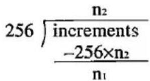
- If the resulting movement would place the printhead outside current margins, the command is ignored.
ABSOLUTE HORIZONTAL POSITION:
(Standard Mode only)
Moves the printhead to an absolute horizontal position.
Name: ESC+\$+n1+n2
Dec.: 27, 36, n1, n2
Hex.: 1B, 24, n₁, n₂
Comments:
● This command moves the printhead to a position n_1+256× n_2 dots (units) from the left margin. Each unit equals 1/60th of an inch.
● To calculate n_1 and n_2 , divide 256 into the determined number yielding n_2= the integer portion of the division and n_1= the remainder.
CANCEL:
Clears all data in the buffer.
Name: CAN
Dec.: 24
Hex.: 18
REMOTE PRINTER SELECT:
Selects the printer remotely, enabling it to receive data.
Name: DC1 (Device Control 1)
Dec.: 17
Hex.: 11
Comment:
●Receipt of DC1 while the printer is deselected by DC3 (Standard Mode) /ESC+Q+3 (IBM Mode) enables the printer to receive data.
REMOTE PRINTER DESELECT:
(Standard Mode only)
Deselects the printer remotely, disabling it from receiving data.
Name: DC3 (Device Control 3)
Dec.: 19
Hex.: 13
Comment:
● All data sent in deselect status becomes invalid. In order to return to select status, send DC1 code.
REMOTE PRINTER DESELECT: (IBM Mode only)
Deselects the printer remotely, disabling it from receiving data.
Name: ESC+Q+3
Dec.: 27,81,3
Hex.: 1B, 51, 03
Comment:
● All data sent in deselect status becomes invalid. In order to return to select status, send DC1 code.
DELETE:
(Standard Mode only)
Deletes the last character stored in the buffer.
Name: DEL
Dec.: 127
Hex.: 7F
Comments:
- Only ordinary text may be DELeted. Bit image data, spacing between output generated by consecutive TABs, and character mode designation cannot be DELeted.
●This command is ignored in the word processing mode (ESC+a+1, ESC+a+2 or ESC+a+3).
MSB ON:
(Standard Mode only)
Sets the Most Significant Bit to 1.
Name: ESC+>
Dec.: 27,62
Hex.: 1B,3E
Comments:
- ESC+> has no effect on bit image data.
●This setting can be released by ESC+#.
MSB OFF:
(Standard Mode only)
Sets the Most Significant Bit to 0.
Name: ESC+=
Dec.: 27,61
Hex.: 1B,3D
Comments:
●ESC+= has no effect on bit image data.
●This setting can be released by ESC+#.
MSB CANCEL:
(Standard Mode only)
Sets printer to receive 8th bit "as is".
Name: ESC+#
Dec.: 27,35
Hex.: 1B, 23
Comment:
●This setting has no effect on bit image data.
UNDEFINED CODE PRINTING: (Standard Mode only)
Designates undefined codes in locations 0\~31 DEC , 128\~159 DEC as printing codes for international characters.
Name: Set: ESC+I+1
Release: ESC+I+0
Dec.: 27,73,1
27,73,0
Hex.: 1B, 49, 01
1B, 49, 00
Comments:
●The following characters are printed out by this command.
| Code (DEC) | Print Code | Code (DEC) | Print Code | Code (DEC) | Print Code |
| 0 | à | 22 | .. | 140 | (FF) |
| 1 | è | 23 | Ä | 141 | (CR) |
| 2 | ù | 24 | (CAN) | 142 | (SO) |
| 3 | ò | 25 | Ü | 143 | (SI) |
| 4 | ì | 26 | ä | 144 | § |
| 5 | ° | 27 | (ESC) | 145 | β |
| 6 | £ | 28 | ü | 146 | (DC2) |
| 7 | (-) | 29 | É | 147 | (DC3) |
| 8 | (BS) | 30 | é | 148 | (DC4) |
| 9 | (HT) | 31 | ¥ | 149 | φ |
| 10 | (LF) | 128 | à | 150 | .. |
| 11 | (VT) | 129 | è | 151 | Ä |
| 12 | (FF) | 130 | ù | 152 | (CAN) |
| 13 | (CR) | 131 | ò | 153 | Ü |
| 14 | (SO) | 132 | i | 154 | ä |
| 15 | (SI) | 133 | ° | 155 | (ESC) |
| 16 | § | 134 | £ | 156 | ü |
| 17 | ß | 135 | (-) | 157 | É |
| 18 | (DC2) | 136 | (BS) | 158 | é |
| 19 | (DC3) | 137 | (HT) | 159 | ¥ |
| 20 | (DC4) | 138 | (LF) | ||
| 21 | ø | 139 | (VT) |
- International Characters reside in ASCII location 0-31 DEC and 128-159 DEC . While these characters are normally set as unprintable codes ESC+I+1 sets these as printable characters.
DRAFT FONT DOWNLOADING: (Standard Mode only) Defines down line load characters into specified address locations in RAM.
Name: ESC+&+0+Cs+Ce+At+P1+P2+...+P11 (0≤Cs≤Ce≤255)
Dec.: 27, 38, 2, Cs, Ce, At, P1, P2,..., P11
Hex.: 1B, 26, 02, Cs, Ce, At, P 1 , P 2 , ..., P _11
Comment:
●Refer to page 5-3.
NLQ FONT DOWNLOADING: (Standard Mode only)
Defines download NLQ font.
Name: ESC+&+2+Cs+Ce+At+P 1H +P 1L +...+P _23L (0≤Cs≤Ce≤255)
Dec.: 27, 38, 0, Cs, Ce, At, P 1H , P 1L , ..., P _23L
Hex.: B1, 26, 00, Cs, Ce, At, P 1H , P 1L , ..., P _23L
Comment:
●Refer to page 5-8.
CHARACTER GENERATOR SELECTION:
(Standard Mode only)
Selects the character generator.
Name: ESC+%+n (n=0 or n=1)
Dec.: 27,37,n
Hex.: 1B, 25, n
Comment:
●Refer to page 5-12.
CHARACTER GENERATOR SET COPY:
(Standard Mode only)
Copies internal CG font into downloadable font area.
Name: ESC+:+0+0+0
Dec.: 27,58,0,0,0
Hex.: 1B,3A,00,00,00
Comment:
●Refer to page 5-11,
DOWNLOADABLE CHARACTER DEFINITION:
(IBM Mode only)
Defines download characters into specified address locations.
Name: ESC+=+n1+n2+m+Cs+At1+At2+Data (0≤Cs≤255)
Dec.: 27, 61, n1, n2, m, Cs, At1, At2, Data
Hex.: 1B, 3D, n₁, n₂, m, Cs, At₁, At₂, Data
Comment:
●Refer to Section 5.2 on page 5-13 (Draft and Text) and 5-19 (NLQ) for detailed information.
ESCAPE:
First byte of each multi-byte printer control code.
Name: ESC
Dec.: 27
Hex.: 1B
Comment:
●Cannot be generated by the ESC key on certain computers.
NULL:
Used in certain multi-byte printer control codes.
| Name: | NUL |
| Dec.: | 0 |
| Hex.: | 00 |
RESET PRINTER:
(Standard Mode only)
Initializes printer, causing data in the printer buffer, but not in the receive buffer, to be cleared.
| Name: | ESC+@ |
| Dec.: | 27, 64 |
| Hex.: | 1B, 40 |
Comment:
●Refer to Section 3.4 for an explanation of printer initialization.
PAPER-OUT DETECTION:
Enables paper-out detector.
| Name: | Set: | ESC+9 |
| Dec.: | 27, 57 | |
| Hex.: | 1B, 39 |
| Release: | ESC+8 |
| 27, 56 | |
| 1B, 38 |
Comment:
●Disabling of the paper-out detector causes printing to continue after paper end.

CUT SHEET FEEDER:
(Standard Mode only)
Selects Cut Sheet Feeder (CSF) mode ON/OFF.
Name: ESC+EM+n
Dec.: 27, 25, n
Hex.: 1B, 19, n
Comment:
●The following values of n can be used.
n="0": Cut Sheet Feeder mode is OFF
n="4": Cut Sheet Feeder mode is ON
Note:
- If the Cut Sheet Feeder is not installed and ESC+EM+4 is executed, the printer will not feed the paper correctly.
7. Interfacing
Parallel Interfacing
Communication with a computer is accomplished through a parallel interface based on the Centronics standard.
Specifications:
● data transfer speed: 1000 cps minimum
● synchronization: external STROBE pulse
●logic levels: TTL
●handshaking: BUSY and ACK signals
- connector type: 57-30360 (AMPHENOL) or equivalent
●cable: use a shielded cable 2 meters or less in length.
When the printer is processing data, the BUSY signal is high. The printer will not accept new data from the computer. After the processing is completed, the BUSY signal goes low. (The BUSY signal is also high when the printer is OFF LINE). When the busy signal occurs, the ACK signal goes low indicating to the computer that the data has been processed and the printer is ready to accept more data. This handshaking routine occurs each time a character is sent to the printer.
| BUSY | SLCT | PO | ERROR | |
| ON LINE | LOW | HIGH | LOW | HIGH |
| OFF LINE | HIGH | LOW | LOW | LOW |
| PAPER OUT | HIGH | LOW | HIGH | LOW |
Printer Status Signals

Parallel Interface Connector (Printer side)
7-1 Interfacing
| Signal pin | Return side pin | Signal | Directin |
| 1 | 19 | STB | Input |
| 2 | 20 | DATA 1 | Input |
| 3 | 21 | DATA 2 | |
| 4 | 22 | DATA 3 | |
| 5 | 23 | DATA 4 | |
| 6 | 24 | DATA 5 | |
| 7 | 25 | DATA 6 | |
| 8 | 26 | DATA 7 | |
| 9 | 27 | DATA 8 | |
| 10 | 28 | ACK | Output |
| 11 | 29 | BUSY | Output |
| 12 | PO | Output | |
| 13 | SLCT | Output | |
| 14 | AUTO FEED XT | Input | |
| 15 | |||
| 16 | SG | ||
| 17 | FG | ||
| 18 | +5 V | Output | |
| 31 | 30 | PRIME | Input |
| 32 | ERROR | Output | |
| 33 | SG | ||
| 34 | |||
| 35 | |||
| 36 |
Pin Configuration.
Notes:
● "INPUT" refers to a signal coming into the printer. "OUTPUT" denotes a signal exiting the printer.
- "RETURN" denotes the return side wire of a twisted pair cable and is connected to signal ground.
● All interface signals are at TTL levels.
Connector pin signals
STB...STROBE
●This is a synchronizing input signal to read data into the printer.
●This signal is normally high. Data is read in when it goes low.
●The pulse must be low for at least 1 microsecond.
DATA 1-DATA 8
● These are the input signals which carry the 8 data bits of information.
●The signal is read in synchronization with the STROBE pulse. A high level indicates a logical "1".
●The signal must be present 0.5 microsecond before and after the STROBE pulse.
ACK...ACKNOWLEDGE
●This is an output signal to the computer indicating that the printer is ready to receive the next block of data. It is sent out when the BUSY signal drops from high to low. Therefore, it can be thought of as a data request pulse.
●The signal is normally high. When the condition becomes true, the signal goes low.
●The ACK signal is automatically sent whenever the printer is switched ON LINE.
BUSY
●This output signal indicates the status of the printer. The signal is high when the printer is busy and cannot receive data.
●The signal is high under the following conditions:
1. receive buffer full
2. printer is processing data.
3. printer is OFF LINE
4. printer is in an error condition
PO...PAPER OUT
- This output signal indicates that paper out detector detects the absence of paper.
●The signal is normally low and goes high during a "Paper Out" condition.
SLCT...SELECT
-
SELECT is an output signal which indicates the ON LINE or OFF LINE state of the printer. The signal is high in the ON LINE state and low when OFF LINE.
●The printer enters the ON LINE state: -
when the printer is turned on
- when PRIME is received
- when the RESET command is received
- when the ON LINE switch is pressed
●The printer enters the OFF LINE state:
- when the printer is out of paper
- when the printer is switched OFF LINE
AUTO FEED XT (AFXT)
●This input signal determines if a line feed (LF) command will be added to each carriage return (CR).
- When AFXT is low, CR+LF action occurs. When AFXT is high, only a carriage return is performed.
●DIP SW3 can alter the response by the printer to an AFXT signal. If SW3 is ON, the printer will perform a CR+LF regardless of the level of the incoming signal. When SW3 is OFF, this automatic action is disabled.
SG...SIGNAL GROUND
●The twisted pair return wires (pins 19-30) are connected to signal ground.
FG...FRAME GROUND
●Frame ground is the same as chassis ground.
+5 V
●This is for evaluation only. It should not be used to supply power for external equipment.
PRIME
●This input signal is used to initialize the printer. The signal is normally high and goes low to reset the printer. It can be received anytime during printer operation.
ERROR
● This output signal is an “error” or “fault” condition. Normally high, this signal goes low when an error occurs. An error condition can be caused by:
- a "Paper Out" condition
- the printer being OFF LINE
Timing Chart
(When normal printing code is received)

T1...0.5μs (Min)
T2...1μs (Min)
T3...0.5μs (Min)
T4...5μs (Max)
T5...1ms or less when buffer is not full
1s or less when buffer full
Timing Diagram
The printer does not require any routine maintenance. However, reasonable care of the printer will extend its life. The following preventive and periodic measures are recommended:
Precautions
- Keep all liquids away from the printer. Accidental spillage of a liquid into the printer can cause severe damage.
- Do not block the air flow around the printer. Do not place books, paper, or other items on top of the printer.
- Special care should be taken to protect the printer if it is used in an unfriendly environment such as a machine shop, a dusty or sandy area, etc.
- The life of the printhead can be extended by observing a few simple precautions.
- Do not operate the printer without paper and a ribbon cassette installed.
- Avoid continuous use of the same pins (underline, semi-graphics, etc.) without allowing the printhead time to cool.
- Do not obstruct the movement of the printhead while in operation.
- If the printer is not going to be used for an extended period, unplug the power cord.
Periodic Maintenance
- Cleaning the unit is the most important action the user can perform. The frequency of cleaning is dependent upon the environment.
- Turn the power OFF.
- Clean the case and covers with a soft cloth. Use any mild commercial cleaner on the cloth, do not spray directly on to the printer.
- Remove the top and the smoked plastic covers. Vacuum or dust the inside area of the unit. Be very careful not to damage the flex ribbon cable and the carriage drive belt.
- The platen should be cleaned with denatured alcohol only.
- The carriage guide bar can be lubricated with a very light oil.
Ribbon Cassette
A single ribbon permits the printing of about 4 million characters. When the printing starts to fade, gently push the counter spring in the ribbon cassette hole with the tip of a ballpoint pen or other object. Once the ribbon cassette is mounted onto the carriage and printing is performed for a short time, the characters become darker.

Note:
●Do not push this before the printing starts to fade. If the ribbon has too much ink, the characters may smear when printed.
● Wear and tear of the print head pins may cause serious damage of the ribbon and printing to fade. In such case the printer needs servicing.
Troubleshooting
Most problems associated with the printer can be traced to improper setup, installation, or cabling. The table on page 8-3 will assist the user in identifying and correcting some of the more common problems. If you need additional help, contact the store from which the unit was purchased.
8-2 Maintenance
| SYMPTOM | POSSIBLE CAUSE | PROBABLE SOLUTION |
| Printer does not power up | No AC PowerFuse blown | Check Power CordReplace fuse |
| Power on but printer not printing | Printer not ON LINEInterface cable not connected | Press ON LINE switchSecure connection |
| Printer won't go ON LINE | Out of paper | Replace paper |
| Paper slips around platen | Paper feed selector in “T” position | Set selector to “F” |
| Head moves but does not print | Ribbon not installed correctly. | Re-insert ribbon |
| Paper wrinkles when using tractor feed | No reverse tension on paper.Selector switch is in “F” position | Set paper supply lower than printerSet selector to “T” |
| Paper bunches up around platen | No reverse tension on paper | Set paper supply lower than printer |
| Cannot change form length | * Cut sheet feeder is ON | * Set CSF DIP switch as required |
| Printout double-spaced or no spacing | * Auto LF is ON | * Set Auto LF DIP switch as required |
| Cannot print ASCII characters with code above 127, italic characters printing | 7 bit/8 bit switch set incorrectly on printer or interface | * Set DIP switch SW5 as required |
| Wrong character set printed | * Wrong character set selected | * Set DIP switch SW1, 6, 7, 8 as required |
| Cannot change print mode from computer | FONT and PITCH modes are set incorrectly | Set to Pgm mode Normal conditionRefer to Section 3.1 |
| Fanfold paper is jamming | Paper not installed correctly in tractor | Set selector switch to “F” position to easily remove jammed paper. Set paper correctly with tractor again. (see page 2-7~2-12) |
(* Pertains to DIP switch settings.)
Standard Mode Italic Character Set
| 0 | 1 | 2 | 3 | 4 | 5 | 6 | 7 | 8 | 9 | A | B | C | D | E | F | |
| 0 | NUL | SP | 0 | @ | P | ` | p | SP | 0 | @ | P | ` | p | |||
| 1 | DC1 | ! | 1 | A | Q | a | q | DC1 | / | 1 | A | Q | a | q | ||
| 2 | DC2 | ` | 2 | B | R | b | r | DC2 | ` | 2 | B | R | b | r | ||
| 3 | DC3 | # | 3 | C | S | c | s | DC3 | # | 3 | C | S | c | s | ||
| 4 | DC4 | 4 | D | T | d | t | DC4 | 4 | D | T | d | t | ||||
| 5 | % | 5 | E | U | e | u | % | 5 | E | U | e | u | ||||
| 6 | & | 6 | F | V | f | v | & | 6 | F | V | f | v | ||||
| 7 | ` | 7 | G | W | g | w | ` | 7 | G | W | g | w | ||||
| 8 | BS | CAN | ( | 8 | H | X | h | x | BS | CAN | ( | 8 | H | X | h | x |
| 9 | HT | EM | ) | 9 | J | Y | i | y | HT | EM | ) | 9 | / | Y | i | y |
| A | LF | * | : | J | Z | j | z | LF | * | : | J | Z | j | z | ||
| B | VT | ESC | + | ; | K | [ | k | | | VT | ESC | + | ; | K | [ | k | / |
| C | FF | , | < | L | \ | I | | | FF | , | < | L | \ | I | / | ||
| D | CR | - | = | M | ] | m | } | CR | - | = | M | ] | m | / | ||
| E | SO | . | > | N | ^ | n | ~ | SO | . | > | N | ` | n | ~ | ||
| F | SI | / | ? | O | _ | o | DEL | SI | / | ? | O | - | o | DEL |
Standard Mode Graphic Character Set 1
| 0 | 1 | 2 | 3 | 4 | 5 | 6 | 7 | 8 | 9 | A | B | C | D | E | F | |
| 0 | NUL | SP | 0 | @ | P | ` | p | á | [BHY3] |  | ||||||
| 1 | DC1 | ! | 1 | A | Q | a | q | DC1 | í | ± | ||||||
| 2 | DC2 | ~ | 2 | B | R | b | r | DC2 | ó |  |  | |||||
| 3 | DC3 | # | 3 | C | S | c | s | DC3 | ú | ≤ | ||||||
| 4 | DC4 | 4 | D | T | d | t | DC4 | ñ |  |  | \Sigma | |||||
| 5 | % | 5 | E | U | e | u | Ñ | \sigma | ||||||||
| 6 | & | 6 | F | V | f | v | a |  |  | \mu | ||||||
| 7 | ' | 7 | G | W | g | w | o | \tau | ≈ | |||||||
| 8 | BS | CAN | ( | 8 | H | X | h | x | BS | CAN | ¿ |  | [0747] | \Phi | ||
| 9 | HT | EM | ) | 9 | I | Y | i | y | HT | EM | \theta | |||||
| A | LF | * | : | J | Z | j | z | LF |  |  | \Omega | |||||
| B | VT | ESC | + | ; | K | [ | k | VT | ESC | \frac{1}{2} | δ | |||||
| C | FF | , | < | L | \ | I | \frac{1}{2} | FF | \frac{1}{4} |  |  | \infty | ||||
| D | CR | - | = | M | ] | m | | | CR | i | \phi | 2 | |||||
| E | SO | . | > | N | ^ | n | ~ | SO | << | [42BW] |  | \epsilon | ||||
| F | SI | / | ? | O | _ | o | DEL | SI | >> | \cap$ | SP |


Standard Mode Graphic Character Set 2
| 0 | 1 | 2 | 3 | 4 | 5 | 6 | 7 | 8 | 9 | A | B | C | D | E | F | |
| 0 | NUL | SP | 0 | @ | P | ` | p | Ç | É | á | L | ⊥ | ≡ | |||
| 1 | DC1 | ! | 1 | A | Q | a | q | ü | æ | í | ⊥ | 〒 | ± | |||
| 2 | DC2 | ` | 2 | B | R | b | r | é | Æ | ó | 〒 | 〒 | ≥ | |||
| 3 | DC3 | # | 3 | C | S | c | s | â | ô | ú | 〒 | 〒 | ≤ | |||
| 4 | DC4 | 4 | D | T | d | t | ä | ö | ñ | - | - | 〒 | \Sigma | |||
| 5 | % | 5 | E | U | e | u | à | ò | Ñ | - | + | 〒 | \sigma | |||
| 6 | & | 6 | F | V | f | v | å | û | a | -|| | 〒 | 〒 | \mu | ÷ | ||
| 7 | ` | 7 | G | W | g | w | ç | ù | o | 〒 | 〒 | 〒 | \tau | ≈ | ||
| 8 | BS | CAN | ( | 8 | H | X | h | x | ê | ÿ | ¿ | - | 〒 | 〒 | \Phi | ○ |
| 9 | HT | EM | ) | 9 | I | Y | i | y | ë | Ö | 厂 | -|| | 〒 | 〒 | \theta | • |
| A | LF | * | : | J | Z | j | z | è | ü | -¬ | -|| | 〒 | 〒 | \Omega | • | |
| B | VT | ESC | + | ; | K | [ | k | | | ï | ¢ | 1⁄2 | 〒 | 〒 | 〒 | δ | √ |
| C | FF | , | < | L | \ | l | | | î | £ | 1⁄4 | 〒 | 〒 | 〒 | \infty | i | |
| D | CR | - | = | M | ] | m | ì | ¥ | i | -|| | -|| | 〒 | \phi | ^2 | ||
| E | SO | . | > | N | ^ | n | ~ | Ä | Pt | << | - | 〒 | 〒 | \epsilon$ | ■ | |
| F | SI | / | ? | O | _ | o | DEL | Å | f | >> | -¬ | -⊥ | ∩ | SP |
IBM Mode Character Set 1
| 0 | 1 | 2 | 3 | 4 | 5 | 6 | 7 | 8 | 9 | A | B | C | D | E | F | |
| 0 | NUL | SP | 0 | @ | P | ` | p | á |  | L |  | α | ≡ | |||
| 1 | DC1 | ! | 1 | A | Q | a | q | DC1 | í | [KCOX] | ⊥ | [2066] | β | ± | ||
| 2 | DC2 | " | 2 | B | R | b | r | DC2 | ó | [OCT3] | T | [K5DO] | Γ | ≥ | ||
| 3 | # | 3 | C | S | c | s | ú | [BCKH] | ⊥ | [780Z] | π | ≤ | ||||
| 4 | DC4 | $ | 4 | D | T | d | t | DC4 | ñ | [XCBX] | - |  | Σ | ∫ | ||
| 5 | % | 5 | E | U | e | u | Ñ |  | + | [35BD] | σ | ∫ | ||||
| 6 | & | 6 | F | V | f | v | a | [KBKCI] | = |  | μ | ÷ | ||||
| 7 | , | 7 | G | W | g | w | o |  | | |  | τ | ≈ | ||||
| 8 | BS | CAN | ( | 8 | H | X | h | x | BS | CAN | ¿ | [627S] | L | [WHDS] | Φ | σ |
| 9 | HT | ) | 9 | I | Y | j | y | HT | Γ | [CBTZ] | [BDW7] | [86SC] | θ | ● | ||
| A | LF | * | : | J | Z | j | z | LF | ¬ | [SDW7] | [∅W2] |  | Ω | ● | ||
| B | VT | ESC | + | ; | K | I | k | l | VT | ESC | 1⁄2 |  | [∅52S] | [∅X2S] | δ | √ |
| C | FF | , | < | L | \ | l | | | FF | 1⁄4 |  | [IVW2] | [AKTB] | ∞ | n | ||
| D | CR | - | = | M | ] | m | | | CR | i |  | = |  | ø | 2 | ||
| E | SO | . | > | N | ^ | n | ~ | SO | << | [OXKG] | [8608] | [TYWIC] | ε | ■ | ||
| F | SI | / | ? | O | _ | o | SI | >> | [7] | ≡ | ■ | ∩ | SP |


IBM Mode Character Set 2
| 0 | 1 | 2 | 3 | 4 | 5 | 6 | 7 | 8 | 9 | A | B | C | D | E | F | |
| 0 | NUL | SP | 0 | @ | P | ` | p | Ç | É | á | ≡ | |||||
| 1 | DC1 | ! | 1 | A | Q | a | q | ü | æ | í | ⊥ | ± | ||||
| 2 | DC2 | " | 2 | B | R | b | r | é | Æ | ó | T | ≥ | ||||
| 3 | # | 3 | C | S | c | s | â | ô | ú | ≤ | ||||||
| 4 | DC4 | 4 | D | T | d | t | ä | ö | ñ | ⊥ | \Sigma | |||||
| 5 | § | % | 5 | E | U | e | u | à | ò | Ñ | F | σ | ||||
| 6 | & | 6 | F | V | f | v | á | û | a | \mu | ÷ | |||||
| 7 | , | 7 | G | W | g | w | ç | ù | o | \tau | ≈ | |||||
| 8 | BS | CAN | ( | 8 | H | X | h | x | ê | ÿ | ¿ | \Phi | ο | |||
| 9 | HT | ) | 9 | I | Y | i | y | ē | Ö | 厂 | θ | ● | ||||
| A | LF | * | : | J | Z | j | z | è | Ü | ¬ | \Omega$ | ● | ||||
| B | VT | ESC | + | ; | K | [ | k | | | ī | ¢ | 1⁄2 | δ | √ | |||
| C | FF | , | < | L | \ | l | ] | ī | £ | 1⁄4 | ∞ | n | ||||
| D | CR | - | = | M | I | m | | | j | ¥ | i | ∅ | 2 | ||||
| E | SO | . | > | N | ^ | n | ~ | Ä | Pt | << | ε | ■ | ||||
| F | SI | / | ? | O | _ | o | Ä | f | >> | ∩ | SP |
Note: In NLQ mode, the printer prints Pts for Pt.
IBM Mode All Character Set
| 0 | 1 | 2 | 3 | 4 | 5 | 6 | 7 | 8 | 9 | A | B | C | D | E | F | |
| 0 | ∅ | ▶ | SP | 0 | @ | P | ` | p | Ç | É | á | └ | ⊥ | α | ≡ | |
| 1 | ∅ | ◀ | ! | 1 | A | Q | a | q | ü | æ | í | ⊥ | 〒 | β | ± | |
| 2 | ∅ | ↑ | ” | 2 | B | R | b | r | é | Æ | ó | 〒 | TT | Γ | ≥ | |
| 3 | ♥ | !! | # | 3 | C | S | c | s | â | ô | ú | ├ | └ | π | ≤ | |
| 4 | ♦ | ¶ | $ | 4 | D | T | d | t | ä | ö | ñ | - | - | └ | Σ | |
| 5 | ♣ | § | % | 5 | E | U | e | u | à | ò | Ñ | - | + | F | σ | ↓ |
| 6 | ♠ | - | & | 6 | F | V | f | v | à | û | a | -|| | ─ | ─ | μ | ÷ |
| 7 | • | ♠ | ’ | 7 | G | W | g | w | ç | ù | o | TI | ├ | ─ | τ | ≈ |
| 8 | ☐ | ↑ | ( | 8 | H | X | h | x | ē | ÿ | ¿ | - | └ | ─ | Φ | σ |
| 9 | σ | ↓ | ) | 9 | l | Y | i | y | ē | Ö | ─ | -|| | ─ | ─ | θ | • |
| A | ∅ | → | * | : | J | Z | j | z | è | Ü | -¬ | | | | ─ | ─ | Ω | • |
| B | σ | ← | + | ; | K | [ | k | | | ī | φ | 1⁄2 | ─ | ─ | ─ | δ | √ |
| C | ♀ | L | , | < | L | \ | l | ] | î | £ | 1⁄4 | ─ | ─ | ─ | ∞ | n |
| D | ♪ | ⇔ | - | = | M | ] | m | } | i | ¥ | i | ─ | = | ─ | ø | 2 |
| E | ʃ | ▲ | . | > | N | ^ | n | ~ | Ä | Pt | << | - | ─ | ─ | ε | ■ |
| F | ∅ | ▼ | / | ? | O | _ | o | △ | Ä | f | >> | - | ─ | ─ | ∩ | SP |
Note: In NLQ mode, the printer prints Pts for Pt.

International Character Set
| n | 35c23h | 36u24h | 64d40h | 91c5BH | 92c5CH | 93d5DH | 94c5EH | 96d60h | 123d7BH | 124d7CH | 125d7DH | 126d7EH | |
| USA | 0 | # | @ | [ | \ | ] | - | - | [ | ] | ] | - | |
| FRANCE | 1 | # | à | * | ç | § | - | - | é | ù | è | - | |
| GERMANY | 2 | # | § | Ä | Ö | Ü | - | - | ä | ö | ü | ß | |
| ENGLAND | 3 | £ | @ | [ | \ | ] | - | - | ] | ] | ] | - | |
| DENMARK I | 4 | # | @ | Æ | ∅ | Ä | - | - | æ | ø | á | - | |
| SWEDEN | 5 | # | ø | É | Ä | Ö | Ä | Ü | é | ä | ö | à | ü |
| ITALY | 6 | # | @ | * | \ | é | - | ù | à | ò | è | i | |
| SPAIN I | 7 | Pt | @ | i | Ñ | ¿ | - | - | - | ñ | ] | - | |
| JAPAN | 8 | # | @ | [ | ¥ | ] | - | - | ] | ] | ] | - | |
| NORWAY | 9 | # | ø | É | Æ | ∅ | Ä | Ü | é | æ | ø | à | ü |
| DENMARK II | 10 | # | É | Æ | ∅ | Ä | Ü | é | æ | ø | à | ü | |
| SPAIN II | 11 | # | á | I | Ñ | ¿ | é | - | i | ñ | ó | ú | |
| LATIN AMERICA | 12 | # | $ | á | I | Ñ | ¿ | é | ü | í | ñ | ó | ú |
Proportional Spacing Tables
ASCII Characters Standard Mode Characters
| ASCIIcode | Char. | Width | |
| Normal | Italic | ||
| 0 | à | 12 | 11 |
| 1 | è | 12 | 11 |
| 2 | ù | 11 | 11 |
| 3 | ò | 10 | 11 |
| 4 | ì | 8 | 8 |
| 5 | 8 | 8 | |
| 6 | £ | 12 | 12 |
| 7 | ì | 5 | 10 |
| 8 | ¿ | 12 | 11 |
| 9 | Ñ | 12 | 12 |
| 10 | ñ | 11 | 12 |
| 11 | ɑ | 12 | 12 |
| 12 | Pt | 12 | 12 |
| 13 | À | 12 | 12 |
| 14 | à | 12 | 11 |
| 15 | ç | 11 | 11 |
| 16 | § | 10 | 12 |
| 17 | ß | 11 | 11 |
| 18 | Æ | 12 | 12 |
| 19 | æ | 12 | 12 |
| 20 | ø | 12 | 12 |
| 21 | ø | 12 | 11 |
| 22 | 8 | 9 | |
| 23 | Ä | 12 | 12 |
| 24 | Ö | 12 | 12 |
| 25 | Ü | 12 | 12 |
| 26 | ä | 12 | 11 |
| 27 | ð | 10 | 11 |
| 28 | ü | 11 | 12 |
| 29 | É | 12 | 12 |
| 30 | é | 12 | 11 |
| 31 | ¥ | 12 | 12 |
| 32 | SPACE | 12 | 12 |
| 33 | 5 | 10 | |
| 34 | 8 | 10 | |
| 35 | 12 | 12 | |
| 36 | S | 12 | 11 |
| 37 | % | 12 | 12 |
| 38 | & | 12 | 12 |
| 39 | 5 | 5 | |
| 40 | ( | 6 | 8 |
| 41 | ) | 6 | 3 |
| 42 | * | 12 | 12 |
| 43 | + | 12 | 12 |
| ASCII code | Char. | Width | |
| Normal | Italic | ||
| 44 | . | 7 | 8 |
| 45 | - | 12 | 12 |
| 46 | . | 6 | 7 |
| 47 | / | 10 | 10 |
| 48 | 0 | 12 | 12 |
| 49 | 1 | 8 | 9 |
| 50 | 2 | 12 | 12 |
| 51 | 3 | 12 | 12 |
| 52 | 4 | 12 | 12 |
| 53 | 5 | 12 | 12 |
| 54 | 6 | 12 | 11 |
| 55 | 7 | 12 | 12 |
| 56 | 8 | 12 | 12 |
| 57 | 9 | 12 | 11 |
| 58 | : | 6 | 8 |
| 59 | : | 6 | 9 |
| 60 | < | 10 | 10 |
| 61 | = | 12 | 11 |
| 62 | > | 10 | 9 |
| 63 | ? | 12 | 11 |
| 64 | @ | 12 | 12 |
| 65 | A | 12 | 12 |
| 66 | B | 12 | 12 |
| 67 | C | 12 | 12 |
| 68 | D | 12 | 12 |
| 69 | E | 12 | 12 |
| 70 | F | 12 | 12 |
| 71 | G | 12 | 12 |
| 72 | H | 12 | 12 |
| 73 | I | 8 | 10 |
| 74 | J | 11 | 12 |
| 75 | K | 12 | 12 |
| 76 | L | 12 | 10 |
| 77 | M | 12 | 12 |
| 78 | N | 12 | 12 |
| 79 | O | 12 | 12 |
| 80 | P | 12 | 12 |
| 81 | Q | 12 | 12 |
| 82 | R | 12 | 12 |
| 83 | S | 12 | 12 |
| 84 | T | 12 | 12 |
| 85 | U | 12 | 12 |
| 86 | V | 12 | 11 |
| 87 | W | 12 | 12 |
| ASCII code | Char. | Width | |
| Normal | Italic | ||
| 88 | X | 10 | 12 |
| 89 | Y | 12 | 12 |
| 90 | Z | 10 | 12 |
| 91 | { | 8 | 11 |
| 92 | \ | 10 | 7 |
| 93 | ] | 8 | 11 |
| 94 | · | 12 | 10 |
| 95 | — | 12 | 12 |
| 96 | · | 5 | 5 |
| 97 | a | 12 | 11 |
| 98 | b | 11 | 11 |
| 99 | c | 11 | 11 |
| 100 | d | 11 | 12 |
| 101 | e | 12 | 11 |
| 102 | f | 10 | 12 |
| 103 | g | 11 | 11 |
| 104 | h | 11 | 11 |
| 105 | i | 8 | 9 |
| 106 | j | 9 | 10 |
| 107 | k | 10 | 11 |
| 108 | l | 8 | 9 |
| 109 | m | 12 | 11 |
| 110 | n | 11 | 10 |
| 111 | o | 12 | 11 |
| 112 | p | 11 | 11 |
| 113 | q | 11 | 11 |
| 114 | r | 11 | 10 |
| 115 | s | 12 | 11 |
| 116 | t | 11 | 10 |
| 117 | u | 12 | 11 |
| 118 | v | 12 | 10 |
| 119 | w | 12 | 12 |
| 120 | x | 10 | 12 |
| 121 | y | 12 | 11 |
| 122 | z | 10 | 12 |
| 123 | | | 9 | 10 |
| 124 | | | 5 | 9 |
| 125 | | | 9 | 10 |
| 126 | ~ | 12 | 12 |
| 127 | 0 | 12 | 12 |
Unit: 1/120 inch (0.21mm)
IBM Mode Characters
| ASCII code | Char. | Width |
| 0 | a | 12 |
| 1 | a | 12 |
| 2 | ü | 12 |
| 3 | ö | 11 |
| 4 | l | 8 |
| 6 | £ | 12 |
| 7 | j | 12 |
| 8 | ¿ | 12 |
| 9 | Ñ | 12 |
| 10 | ñ | 12 |
| 12 | Pt | 12 |
| 13 | Å | 12 |
| 14 | å | 12 |
| 15 | ç | 12 |
| 16 | § | 12 |
| 18 | Æ | 12 |
| 19 | æ | 12 |
| 23 | Ä | 12 |
| 24 | Ö | 11 |
| 25 | Ü | 12 |
| 26 | ä | 12 |
| 27 | ö | 11 |
| 28 | ü | 12 |
| 29 | É | 12 |
| 30 | ó | 12 |
| 31 | ¥ | 12 |
| 32 | SPACE | 12 |
| 33 | ! | 5 |
| 34 | " | 8 |
| 35 | # | 12 |
| 36 | § | 12 |
| 37 | % | 12 |
| 38 | & | 12 |
| 39 | ' | 6 |
| 40 | ( | 6 |
| 41 | ) | 6 |
| 42 | * | 12 |
| 43 | ÷ | 12 |
| 44 | , | 6 |
| 45 | - | 12 |
| 46 | . | 6 |
| 47 | / | 10 |
| 48 | 0 | 12 |
| 49 | 1 | 8 |
| ASCII code | Char. | Width |
| 50 | 2 | 12 |
| 51 | 3 | 12 |
| 52 | 4 | 12 |
| 53 | 5 | 12 |
| 54 | 6 | 12 |
| 55 | 7 | 12 |
| 56 | 8 | 12 |
| 57 | 9 | 12 |
| 58 | : | 6 |
| 59 | ; | 6 |
| 60 | < | 10 |
| 61 | = | 12 |
| 62 | > | 10 |
| 63 | ? | 10 |
| 64 | @ | 12 |
| 65 | A | 12 |
| 66 | B | 12 |
| 67 | C | 12 |
| 68 | D | 12 |
| 69 | E | 12 |
| 70 | F | 12 |
| 71 | G | 12 |
| 72 | H | 12 |
| 73 | I | 8 |
| 74 | J | 12 |
| 75 | K | 12 |
| 76 | L | 12 |
| 77 | M | 12 |
| 78 | N | 12 |
| 79 | O | 12 |
| 80 | P | 12 |
| 81 | Q | 12 |
| 82 | R | 12 |
| 83 | S | 12 |
| 84 | T | 12 |
| 85 | U | 12 |
| 86 | V | 12 |
| 87 | W | 12 |
| 88 | X | 10 |
| 89 | Y | 12 |
| 90 | Z | 12 |
| 91 | [ | 8 |
| 92 | \ | 10 |
| 93 | ] | 8 |
| ASCII code | Char. | Width |
| 94 | - | 12 |
| 95 | - | 12 |
| 96 | r | 6 |
| 97 | a | 12 |
| 98 | b | 11 |
| 99 | c | 11 |
| 100 | d | 11 |
| 101 | e | 12 |
| 102 | f | 12 |
| 103 | g | 11 |
| 104 | h | 12 |
| 105 | i | 8 |
| 106 | j | 8 |
| 107 | k | 10 |
| 108 | l | 8 |
| 109 | m | 12 |
| 110 | n | 12 |
| 111 | o | 11 |
| 112 | p | 11 |
| 113 | q | 11 |
| 114 | r | 11 |
| 115 | s | 12 |
| 116 | t | 10 |
| 117 | u | 12 |
| 118 | v | 12 |
| 119 | w | 12 |
| 120 | x | 10 |
| 121 | y | 12 |
| 122 | z | 10 |
| 123 | { | 9 |
| 124 | | | 4 |
| 125 | } | 9 |
| 126 | ~ | 12 |
| 127 | ∅ | 12 |
Unit: 1/120 inch (0.21mm)
IBM Graphic Characters Standard Mode Characters
| ASCIIcode | Char. | Width | |
| Normal | Italic | ||
| 21 | § | 10 | 12 |
| 128 | Ç | 12 | 12 |
| 129 | ü | 11 | 12 |
| 130 | é | 12 | 11 |
| 131 | ä | 12 | 12 |
| 132 | ä | 12 | 11 |
| 133 | ä | 12 | 11 |
| 134 | ä | 12 | 11 |
| 135 | ç | 11 | 11 |
| 136 | ö | 12 | 12 |
| 137 | ö | 12 | 11 |
| 138 | è | 12 | 11 |
| 139 | ī | 8 | 10 |
| 140 | j | 10 | 11 |
| 141 | i | 8 | 8 |
| 142 | Ä | 12 | 12 |
| 143 | Ä | 12 | 12 |
| 144 | É | 12 | 12 |
| 145 | æ | 12 | 12 |
| 146 | Æ | 12 | 12 |
| 147 | ö | 10 | 12 |
| 148 | ö | 10 | 11 |
| 149 | ö | 10 | 11 |
| 150 | ü | 11 | 11 |
| 151 | ü | 11 | 11 |
| 152 | y | 12 | 11 |
| 153 | Ö | 12 | 12 |
| 154 | Ü | 12 | 12 |
| 155 | ¢ | 11 | 11 |
| 156 | £ | 12 | 12 |
| 157 | ¥ | 12 | 12 |
| 158 | Pl | 12 | 12 |
| 159 | f | 11 | 12 |
| 160 | ä | 12 | 11 |
| 161 | I | 8 | 10 |
| 162 | ö | 10 | 12 |
| 163 | ü | 11 | 11 |
| 164 | ñ | 11 | 12 |
| 165 | Ñ | 12 | 12 |
| 166 | a | 12 | 11 |
| 167 | o | 12 | 12 |
| 168 | ¿ | 12 | 11 |
| 169 | — | 12 | 12 |
| 170 | — | 12 | 12 |
| ASCII code | Char. | Width | |
| Normal | Rallc | ||
| 171 | 12 | 12 | 12 |
| 172 | 14 | 12 | 12 |
| 173 | 1 | 5 | 10 |
| 174 | << | 12 | 12 |
| 175 | >> | 12 | 12 |
| 224 | 12 | 12 | |
| 225 | 11 | 11 | |
| 226 | 10 | 12 | |
| 227 | 12 | 12 | |
| 228 | 10 | 12 | |
| 229 | 11 | 12 | |
| 230 | 11 | 12 | |
| 231 | 12 | 12 | |
| 232 | 10 | 12 | |
| 233 | 12 | 12 | |
| 234 | 12 | 12 | |
| 235 | 12 | 11 | |
| 236 | 12 | 12 | |
| 237 | 12 | 12 | |
| 238 | 10 | 10 | |
| 239 | 10 | 12 | |
| 240 | 12 | 12 | |
| 241 | ± | 12 | 12 |
| 242 | ≥ | 10 | 10 |
| 243 | ≤ | 10 | 10 |
| 246 | ÷ | 12 | 12 |
| 247 | ≈ | 12 | 12 |
| 248 | ^ | 8 | 8 |
| 249 | 6 | 6 | |
| 250 | · | 6 | 6 |
| 251 | 12 | 12 | |
| 252 | ^n | 8 | 8 |
| 253 | ^2 | 8 | 8 |
| 254 | 8 | 8 | |
| 255 | SP | 12 | 12 |
Unit: 1/120 inch (0.21mm)
IBM Mode Characters
| ASCII code | Char. | Width |
| 0 | 0 | 12 |
| 1 | ♀ | 12 |
| 2 | ● | 12 |
| 3 | ♥ | 12 |
| 4 | ◆ | 10 |
| 5 | ♣ | 12 |
| 6 | ♠ | 12 |
| 7 | • | 12 |
| 8 | □ | 12 |
| 9 | ○ | 12 |
| 10 | □ | 12 |
| 11 | ○ | 12 |
| 12 | ♀ | 12 |
| 13 | P | 12 |
| 14 | # | 12 |
| 15 | o | 12 |
| 16 | ▶ | 12 |
| 17 | ◀ | 12 |
| 18 | ↓ | 12 |
| 19 | !! | 12 |
| 20 | ¶ | 12 |
| 22 | — | 12 |
| 23 | ↓ | 12 |
| 24 | ↑ | 12 |
| 25 | ↓ | 12 |
| 26 | → | 12 |
| 27 | ← | 12 |
| 28 | L | 12 |
| 29 | ← | 12 |
| 30 | ▲ | 12 |
| 31 | ▼ | 12 |
| 127 | △ | 12 |
| 128 | Q | 12 |
| 131 | À | 12 |
| 136 | è | 12 |
| 139 | T | 9 |
| 140 | I | 10 |
| 147 | △ | 11 |
| 150 | û | 12 |
| 152 | ÿ | 11 |
| 155 | ¢ | 12 |
| 159 | f | 12 |
| 160 | à | 12 |
| 161 | I | 12 |
| ASCII code | Char. | Width |
| 162 | 12 | |
| 163 | 12 | |
| 166 | 12 | |
| 167 | 12 | |
| 169 | 一 | 12 |
| 170 | 一 | 12 |
| 171 | 1⁄2 | 12 |
| 172 | 1⁄4 | 12 |
| 174 | < < | 12 |
| 175 | > > | 12 |
| 224 | 12 | |
| 225 | 12 | |
| 226 | 11 | |
| 227 | 12 | |
| 228 | 12 | |
| 229 | 12 | |
| 230 | 12 | |
| 231 | 11 | |
| 232 | 12 | |
| 233 | 12 | |
| 234 | 12 | |
| 235 | 12 | |
| 236 | 12 | |
| 237 | 12 | |
| 238 | 10 | |
| 239 | 12 | |
| 240 | 12 | |
| 241 | ± | 12 |
| 242 | ≥ | 10 |
| 243 | ≤ | 10 |
| 246 | ÷ | 12 |
| 247 | = | 11 |
| 248 | 8 | |
| 249 | 6 | |
| 250 | · | 6 |
| 251 | 12 | |
| 252 | ^n | 10 |
| 253 | ^2 | 8 |
| 254 | 8 |
Unit: 1/120 inch (0.21mm)
Download Character Matrix Blanks: Draft
9×11

natural_image
Grid pattern with uniform black lines on white background, no text or symbols present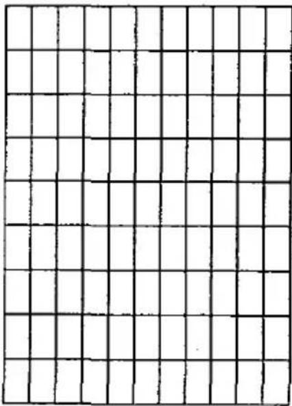
natural_image
Blank grid paper with no text, numbers, or symbolsDownload Character Matrix Blanks: NLQ
18×23

natural_image
Grid pattern with uniform black lines on white background, no text or symbols presente
Make copies of this page first.
Then use blank matrices to design your down line load characters.
Paper
1. Fanfold paper
A list of the paper which may be used with this unit is provided below.
Width: 102\~254 mm {4\~10 inches}
Quality and number of sheets:
| Type of paper | Sheets | Weight | |||
| in lbs | in g/m2 | ||||
| rear | bottom | rear | bottom | ||
| Fine-quality paper | 1 | 16~20 | 18~24 | 60~90 | 60~83 |
| Non-carbon | 2~4 | 11~14 (17*) | 41~53 (64*) | ||
| Multi-layered with carbon | 2 | 11~14 (17*) | 41~53 (64*) | ||
* only for the last sheet
Notes:
●For optimum paper handing, when using some types of thicker multi-part fanfold paper, we suggest the use of the bottom feed paper path.
- When using multi-part fanfold paper in environments which have very high or low temperature and/or humidity, we recommend the use of the bottom feed to optimize paper handling and print quality.
● In multi-layered paper with carbon, the carbon is equivalent to a sheet of paper.
● "Weight in pounds" represents the weight of 500 [17×22 inches (432×559 mm)] sheets.
● The printer will handle multi-part papers up to 0.013 inch (0.32 mm) thick. Up to 4 copies of 14 lb. chemical release paper can be used.
2. Single Sheet
Width: 102\~297 mm {4\~11.7 inches}
Height: 127\~363 mm {5\~14.3 inches}
Weight in pounds (g/m²): 53\~90 g/m2 {14\~24 lbs}

3. Envelope
10 size envelope is recommended. Since envelopes vary in size, paper weight and construction, we cannot guarantee print quality and paper handling for all types of envelopes.

Printing Area
1. Fanfold paper
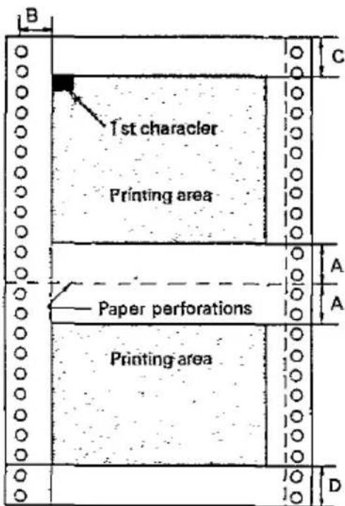
| Rear | Bottom | |
| A | 25.4 mm {1"} | |
| B | 19.4 mm {0.76"} | |
| C | 20.3 mm {0.80"} | 91.5 mm {3.6"} |
| D | 38.1 mm {1.5"} | 24.1 mm {0.95"} |
A: Value A indicates the positions near the paper perforations where the printing quality may not be optimum.
B: Value B indicates the position where the first character is printed. (When the left tractor is set on the left end.)
C: Value C indicates the area from the top of the paper to the position where the first character is printed.
D: Value D indicates the position where paper out is detected.
2. Single Sheet

| B | 47 mm {1.85"} |
| C | 20.3 mm {0.80"} |
| D | 25.4 mm {1"} |
B: Value B indicates the position where the first character is printed.
C: Value C indicates the area from the top of the paper to the position where the first character is printed.
D: Value D indicates the position where paper out is detected.
Envelope

| B | 25.4 mm {1"} |
| C | 20.3 mm {0.80"} |
| D | 25.4 mm {1"} |
E-1 Appendix
Software commands of Standard mode and IBM mode descriptions are not indexed here.
For page references for commands see pages 6-1 through 6-9 in section 6.
A
Adjusting the printing head gap 2-4
ASCII tables B-1
B
Back tension plate 3-5
Bit image 5-21
8-pin Bit Image 5-23
9-pin Bit Image 5-25
C
Center paper support 1-6
Character pitch 5-1
Character set 1-2
Standard mode A-1
IBM mode A-4
International A-7
Column indicator light 1-5,3-3
Connecting to a Computer 2-14
Control Table 1-5,3-2
Setting 3-2
D
Detectors 3-6
DIP switch setting 2-15
Dot density 5-21
Double height printing 5-2
Double printing 5-2
Double width printing 5-2
Download characters 5-3
E
Emphasized printing 5-2
EZ Set Operator panel 1-1, 1-5, 3-1
F
Front Panel Switches 1-5,3-1
FF/PITCH switches 1-5, 3-1
FUNCTION switch 1-5,3-1
LF/FORM LENGTH 1-5,3-1
Function mode 3-1
H
Head gap lever 1-6,2-4
Head nose 2-3
Hex. Dump 3-7
I
Initialization 3-7
Ink ribbon cassette 2-1,8-2
Interfacing 7-1
M
MEMO LOAD 1-1,3-4
N
Nose cover 2-3
0
| ON LINE indicator light | 1-5, 3-1 |
| ON LINE switch | 1-5, 3-1 |
| 3-2, 3-6 | |
| Out of paper detector | 3-6 |
| Overheat detector | 3-6 |
| Overline printing | 5-2 |
P
| Paper | D-1 |
| Envelope | D-2 |
| Installation | 2-5~2-12 |
| Specifications | 1-2~1-4 |
| Paper bail release lever | 1-6, 2-6, 2-9 |
| Paper feed selector | 1-6, 2-5 |
| Paper guide | 1-6, 2-5 |
| Parallel Interface connector | 1-7, 7-1 |
| Platen knob | 1-6, 1-7 |
| POWER/PAPER OUT | |
| Indicator light | 1-5 |
| Power switch | 1-7, 2-4 |
| Power up | 2-4 |
| Printhead | 1-6 |
| Printing Area | E-1 |
| Print pitch | 1-1, 5-1 |
| Proportional Spacing tables | B-1 |
R
| ROW indicator light | 1-5 |
| RS-232C serial interface | 1-2 |
S
| Self test | 2-13 |
| Site requirements | 2-1 |
| Smoked plastic cover | 1-6, 2-2 |
T
| Top cover | 1-6 |
| Top of form | 3-5 |
| Tractor | 1-6, 2-5, 2-7 |
| Tractor clamping lever | 1-6, 2-7 |
| 2-10 |
U
| Underline printing | 5-2 |
W
| Wing tab | 2-3 |
OPTIONS and SUPPLIES
KX-P19 RS-232C/Current Loop Serial Interface Board
KX-PS10 RS-232C Adapter
KX-PS12 Apple Interface Adapter
KX-P37 Auto Cut Sheet Feeder (Single bin)
KX-P43 32K Buffer Chip
KX-P115i Ribbon Cassette (Black)
934
Matsushita Electric Industrial Co., Ltd.
Central P.O. Box 288, Osaka 530-91, Japan
Printed in U.K.
PJQX6316ZA C0691CJ0
- Operating Instructions
- FOR USE IN U.K.
- IMPORTANT:
- WARNING
- Introduction 1-1
- Set up 2-1
- Operation 3-1
- Software Introduction 4-1
- KX-P1170 Features 5-1
- Software Commands 6-1
- Interfacing 7-1
- Maintenance.... 8-1
- OPTIONS and SUPPLIES
- Introduction
- Product Overview
- 1-1 Introduction
- Specifications
- 1-3 Introduction
- Names of the Parts
- The Front View
- 1-5 Introduction
- Site Requirements
- Unpacking and Inspection
- Note:
- Mounting the Ribbon Cassette
- Power Up
- Adjusting the Printhead Gap
- Paper Installation
- Single Sheet and Envelopes
- Fanfold Paper from Rear
- Fanfold Paper from Bottom
- Self Test
- Connecting to a Computer
- DIP Switches
- -Changing the DIP switch settings
- SW1 Printer Mode
- SW2 Skip Perforation
- SW3 Automatic LF
- SW4 Cut Sheet Feeder
- SW5 7/8 Bit Code Selection
- SW6, 7 & 8 Character Set
- SW6 (IBM mode)
- SW7 (IBM mode)
- SW8 (IBM mode)
- Front Panel Switches
- FUNCTION / EXIT switch
- ON LINE / FONT switch
- FF / PITCH switch
- LF / FORM LENGTH switch
- Control Table
- Setting Font/Pitch/Form Length
- Setting Font
- Setting Pitch
- Setting Form Length
- 3-2 Operation
- EXAMPLES
- Feeding the paper
- 3
- Form Feed
- Line Feed
- Memo Load (LOAD/PARK)
- To print on the single sheet
- After printing on the single sheet
- 3-4 Operation
- Aligning the Top of Form
- To set the Top of Form
- Detectors
- Out of Paper Detector
- Overheat Detector
- Initialization
- Hex Dump
- To enter the Hex Dump mode:
- To release the Hex Dump mode:
- Software Introduction
- Introduction
- Control Codes
- 4-1 Software Introduction
- Entering Control Codes through Commercial Software Packages
- Entering Control Codes Directly from the Keyboard
- Entering Control Codes from Within a Program
- Entering Hexadecimal Code
- Control Codes
- Special Code IBM PC or Compatible
- 4-7 Software Introduction
- Print Feature Control
- Print Quality and Font
- Character Pitch
- (Print Example)
- Character Highlighting
- Download Characters
- Standard Mode (Epson FX-86e/FX-800)
- DRAFT FONT DOWNLOADING:
- Example:
- Explanation:
- Comments:
- NLQ FONT DOWNLOADING:
- Comment:
- ROM CHARACTER GENERATOR SET COPY:
- CHARACTER GENERATOR SELECTION:
- IBM Mode
- Draft and Text Character Downloading
- At _1 is attribute byte 1
- Designing Draft and Text download characters.
- 5-16 KX-P1170 Features
- Example
- NLQ FONT DOWNLOADING
- Bit Image (Graphics)
- 5-22 KX-P1170 Features
- 8-Pin Bit Image Mode
- 9-Pin Bit Image Mode (Standard Mode only)
- Software Commands
- Standard Mode (FX-86e/FX-800)
- IBM Mode (Proprinter II)
- ITALIC FONT:
- NLQ FONT STYLE:
- NEAR LETTER QUALITY (NLQ) FONT:
- PRINT MODE SELECT:
- DOUBLE STRIKE PRINTING: (IBM Mode only)
- SUB/SUPERSCRIPT FONT:
- PICA PITCH:
- ELITE PITCH:
- MICRON PRINTING:
- COMPRESSED PRINTING PITCH:
- (Standard Mode)
- (IBM Mode)
- PROPORTIONAL SPACING: (Standard Mode only)
- PROPORTIONAL SPACING:
- CHARACTER DOT SPACING:
- PROGRAMMABLE PITCH/HIGHLIGHTING:
- EMPHASIZED PRINTING:
- DOUBLE PRINTING:
- DOUBLE WIDTH PRINTING-SINGLE LINE:
- DOUBLE WIDTH PRINTING:
- DOUBLE HIGH PRINTING:
- DOUBLE HIGH AND DOUBLE WIDTH PRINTING:
- UNDERLINING:
- OVERLINING: (IBM Mode only)
- INTERNATIONAL CHARACTER SET:
- IBM CHARACTER SET I:
- IBM CHARACTER SET II:
- ALL CHARACTER CHART PRINTING
- (Continuous):
- ALL CHARACTER CHART PRINTING (Single):
- ALTERNATE CHARACTER SET:
- STANDARD DENSITY GRAPHICS:
- DOUBLE DENSITY GRAPHICS:
- DOUBLE SPEED, DOUBLE DENSITY GRAPHICS:
- QUADRUPLE DENSITY GRAPHICS:
- 8-PIN BIT IMAGE MODE SELECTION:
- 9-PIN BIT IMAGE MODE SELECTION:
- BIT IMAGE MODE REASSIGNMENT:
- 1/8 INCH PAPER FEED:
- 7/72 INCH PAPER FEED:
- 1/6 INCH PAPER FEED:
- n/72 INCH PAPER FEED:
- n/216 INCH PAPER FEED:
- AUTOMATIC LINE FEED MODE: (IBM Mode only)
- FORM FEED (FF):
- LINE FEED (LF):
- n/216 INCH REVERSE DIRECTION SINGLE LINE PAPER FEED: (Standard Mode only
- Notes:
- PAGE LENGTH (INCHES):
- PAGE LENGTH (LINES):
- RIGHT MARGIN:
- LEFT MARGIN:
- MARGIN SET:
- LEFT ALIGNMENT:
- AUTO CENTERING:
- RIGHT ALIGNMENT:
- AUTO JUSTIFICATION:
- TOP OF FORM:
- SKIP PERFORATION:
- HORIZONTAL TAB STOP SETTING:
- HORIZONTAL TAB EXECUTION:
- VERTICAL TAB STOP SETTING:
- VERTICAL TAB EXECUTION:
- ALL TAB INITIAL CLEAR:
- VFU CHANNEL SELECTION:
- VFU SETTING:
- BACKSPACE:
- CARRIAGE RETURN:
- ONE LINE UNIDIRECTION PRINT:
- SINGLE DIRECTION:
- HALF SPEED PRINTING:
- RELATIVE HORIZONTAL POSITION:
- ABSOLUTE HORIZONTAL POSITION:
- CANCEL:
- REMOTE PRINTER SELECT:
- REMOTE PRINTER DESELECT:
- REMOTE PRINTER DESELECT: (IBM Mode only)
- DELETE:
- MSB ON:
- MSB OFF:
- MSB CANCEL:
- UNDEFINED CODE PRINTING: (Standard Mode only)
- CHARACTER GENERATOR SET COPY:
- DOWNLOADABLE CHARACTER DEFINITION:
- ESCAPE:
- NULL:
- RESET PRINTER:
- PAPER-OUT DETECTION:
- CUT SHEET FEEDER:
- Interfacing
- Parallel Interfacing
- Specifications:
- 7-1 Interfacing
- Connector pin signals
- STB...STROBE
- DATA 1-DATA 8
- ACK...ACKNOWLEDGE
- BUSY
- PO...PAPER OUT
- SLCT...SELECT
- AUTO FEED XT (AFXT)
- SG...SIGNAL GROUND
- FG...FRAME GROUND
- +5 V
- PRIME
- ERROR
- Precautions
- Periodic Maintenance
- Ribbon Cassette
- Troubleshooting
- 8-2 Maintenance
- Standard Mode Graphic Character Set 1
- Proportional Spacing Tables
- ASCII Characters Standard Mode Characters
- Download Character Matrix Blanks: Draft
- Download Character Matrix Blanks: NLQ
- Paper
- Fanfold paper
- Single Sheet
- Envelope
- size envelope is recommended. Since envelopes vary in size, paper weight and construction, we cannot guarantee print quality and paper handling for all types of envelopes.
- Printing Area
- Envelope
- E-1 Appendix
- A
- B
- C
- D
- E
- F
- H
- I
- M
- N
Marque : PANASONIC
Modèle : KX-P1170
Catégorie : Imprimante