
KX-P3200 - Imprimante PANASONIC - Notice d'utilisation et mode d'emploi gratuit
Retrouvez gratuitement la notice de l'appareil KX-P3200 PANASONIC au format PDF.


| Type de produit | Imprimante matricielle 24 aiguilles |
| Marque | Panasonic |
| Modèle | KX-P3200 |
| Résolution max | 360 x 360 dpi |
| Nombre d'aiguilles | 24 |
| Vitesse d'impression | Jusqu'à 300 cps (caractères par seconde) |
| Langages d'émulation | Epson LQ, IBM Proprinter |
| Types de papier supportés | Papier continu (perforé) et feuilles individuelles |
| Largeur de papier max | 381 mm (15 pouces) |
| Interfaces | Parallèle (Centronics), série (RS-232C) |
| Nombre de copies | Original + 3 copies (formulaire) |
| Dimensions (L x P x H) | 536 x 374 x 164 mm |
| Poids | 7,2 kg |
| Alimentation | AC 100-240V, 50/60 Hz |
| Consommation électrique | 53 W en impression, 12 W en veille |
| Niveau sonore | 52 dB(A) en impression |
| Type de ruban | Cartouche ruban noir (réf. KX-P314) |
| Raccordement | Câble parallèle ou série (non inclus) |
| Fonctions principales | Impression bidirectionnelle, gestion de formulaires, polices internes |
| Entretien et nettoyage | Nettoyer les aiguilles et les rouleaux avec un kit de nettoyage adapté |
| Sécurité | Ne pas exposer à l'eau ni à une humidité excessive |
| Pièces détachées et réparabilité | Ruban, tête d'impression, circuit électronique disponibles |
| Informations générales | Notice d'utilisation disponible en PDF |
FOIRE AUX QUESTIONS - KX-P3200 PANASONIC
Questions des utilisateurs sur KX-P3200 PANASONIC
0 question sur cet appareil. Repondez a celles que vous connaissez ou posez la votre.
Poser une nouvelle question sur cet appareil
Téléchargez la notice de votre Imprimante au format PDF gratuitement ! Retrouvez votre notice KX-P3200 - PANASONIC et reprennez votre appareil électronique en main. Sur cette page sont publiés tous les documents nécessaires à l'utilisation de votre appareil KX-P3200 de la marque PANASONIC.
MODE D'EMPLOI KX-P3200 PANASONIC
Operating Instructions
Forms Printer
Model No. KX-P3200

natural_image
Exterior view of a Panasonic portable air conditioner unit (no visible text or symbols on body)Congratulations on purchasing a Panasonic printer.
This printer is a versatile, high quality 9-pin dot matrix printer which is designed to meet the needs of your office. This printer has been factory set to operate with the most popular software packages. Your application software should control the printer functions. In most cases, there will be no need to change the factory settings.
The serial number of the unit may be found on the label on the rear of the unit. For your convenience, note this number below, and retain this book, along with your proof of purchase, to serve as a permanent record of your purchase in the event of a theft, or for future reference.
MODEL NO. KX-P3200
NAME OF DEALER
SERIAL NO.
DATE OF PURCHASE
Warning:
- The power source voltage of this unit is listed on the nameplate. Plug the printer's 3-prong cord into an outlet with the proper voltage.
• To prevent fire or shock hazard, do not expose this product to rain or any type of moisture.
Caution:
- When you operate this equipment, the mains socket-outlet should be near the equipment and should be easily accessible.
- To prevent parallel/serial interface and printhead from static electricity damage, before you touch them, discharge any static electricity from your hands by touching a grounded metal surface. (However, do not touch the printhead when it is hot.)
FOR YOUR SAFETY
To ensure safe operation the three-pin plug supplied must be inserted only into a standard three-pin power point which is effectively earthed through the normal household wiring.
Extension cords used with the equipment must be three-core and be correctly wired to provide connection to earth. Improperly wired extension cords are a major cause of fatalities.
The fact that the equipment operates satisfactorily does not imply that the power point is earthed and that the installation is completely safe. For your safety, if in any doubt about the effective earthing of the power point, consult a qualified electrician.
If the plug cannot be inserted into the mains socket-outlet, contact a licensed electrician to replace the outlet with properly grounded one. Do not defeat the purpose of the grounding plug (ex. do not use a conversion plug).
IBM, IBM-PC and Proprinter are trademarks of International Business Machines Corporation.
Microsoft® and Windows® are registered trademarks of Microsoft Corporation in the United States and/or other countries.
Epson is a trademark of Seiko Epson Corporation.
Printer Driver Program for Windows 3.1: All Rights Reserved. © COPYRIGHT 1990 – 1992 Microsoft Corporation.
Printer Driver Program for Windows 95: All Rights Reserved. © COPYRIGHT 1991 – 1995 Microsoft Corporation.
Any details given in these Operating Instructions are subject to change without notice.
All Rights Reserved. © COPYRIGHT 1996 KYUSHU MATSUSHITA ELECTRIC CO., LTD.
Unpacking
Having unpacked the printer, make sure none of the contents shown below are missing or damaged. Report damages or shortages to the store from which the unit was purchased.

natural_image
Simple line drawing of a rectangular prism with no text or symbolsPrinter

Ribbon cassette (KX-P181)

Platen knob

Power cord
Setup Disk

Operating Manual
Quick Start Guide
- The Setup Disk contains a Printer Driver for Windows 3.1 and Windows 95 (P. 11), a Control Panel Software program (P. 13) and a Command Reference program (P. 15).
- To use this Setup Disk, you need to have an IBM-PC or a compatible computer with 3.5" floppy disk drive.
Note:
- It is recommended that you save the original carton and packing materials for proper shipping and transporting of the printer.
2 Warning/Caution
2 Unpacking
Chap. 1 Read Me First
| 4 | End-User License Agreement | 5 | Precautions |
| 5 | Cautions | 6 | Parts of the Printer |
| 5 | Operating Environment |
Chap. 2 Setup
| 7 | Connecting to a Computer | 9 | Installing Paper |
| 7 | Power Supply | 10 | Tearing off Paper |
| 8 | Installing Ribbon Cassette | 10 | Self Test |
| 9 | Handling Paper | 10 | Printer Driver Selection |
Chap. 3 Installing and Using the Setup Disk
| 11 | Installing the Setup Disk | 13 | Using the Setup Disk |
| 11 | For DOS | 13 | Control Panel Software Program |
| 11 | For Windows 3.1 | 15 | Command Reference Program |
| 12 | For Windows 95 |
Chap. 4 Using the Control Panel
| 16 | Using the Control Panel and DIP Switch | 17 | Paper Out Detector |
| 16 | Selecting a Character Font | 18 | Initial Setup Mode |
| 16 | Line Feed/Form Feed (LF/FF) | 19 | Returning All Current Settings to the Factory Settings |
| 16 | Paper Loading (LOAD) | ||
| 17 | Top of Form Function (TOF SET) | 19 | Using the DIP Switch |
Chap. 5 Periodic Maintenance/Troubleshooting
| 20 | Periodic Maintenance | 21 | Options and Supplies |
| 20 | Troubleshooting |
Appendix
| 24 | Printer Specifications | 26 | Interfacing |
| 25 | Paper Specifications | 26 | Parallel Interfacing |
| 25 | Printing Area | 26 | Serial Interfacing |
| 27 | Index |
The Setup Disk contains the following programs and informations. Please refer to this manual how to use.
- Printer Driver for Windows 3.1 ( P. 11)
• Printer Driver for Windows 95 ( P. 12)
• Control Panel Software Program ( P. 13)
• Command Reference Program ( P. 15)
• Character Set Tables ( P. 15)
• Proportional Spacing Tables ( P. 15)
End-User License Agreement
THIS IS A LEGAL AGREEMENT BETWEEN YOU AND PANASONIC. CAREFULLY READ ALL THE TERMS AND CONDITIONS OF THIS AGREEMENT PRIOR TO OPENING THE PACKET OF SOFTWARE PROGRAM. OPENING THE PACKET INDICATES YOUR ACCEPTANCE OF THESE TERMS AND CONDITIONS. If you do not agree to these terms and conditions, return the unopened packet and the other components of the Panasonic product to the place of purchase and your money will be refunded. No refunds will be given for the products that have an opened packet or missing components.
1. COPYRIGHT:
Panasonic has the right to license or has been granted to license the enclosed Software Program ("SOFTWARE"), developed and copyrighted by Kyushu Matsushita Electric Co., Ltd. or its licensor ("Licensor"). You acknowledge that you are receiving only a LIMITED LICENSE TO USE the SOFTWARE and related documentation, and that you shall obtain no title, ownership nor any other rights in or to the SOFTWARE and related documentation, all of which title and rights shall remain with Licensor and Panasonic.
2. LICENSE:
(1) You have the non-exclusive right to use the one copy of the SOFTWARE on a single computer used by single user. Installation of the SOFTWARE on a network server for the purpose of distribution to one or more other computers shall not be granted in this Agreement. (2) You may not copy, reproduce, or permit to be copied or reproduced, the SOFTWARE or related documentation for any purpose, except that you may either (a) make a reasonable quantity of copies of the SOFTWARE solely for backup or archival purposes, or (b) transfer the SOFTWARE to a single hard disk, provided that you keep the original solely for backup or archival purposes. (3) You may not rent or lease the SOFTWARE, but you may transfer your right under this License Agreement on a permanent basis, provided that you transfer this Agreement, all copies of the SOFTWARE, all related documentation and your Panasonic product, and the recipient thereof agrees to the terms of this Agreement. (4) You may not reverse engineer, decompile or disassemble the SOFTWARE, except that in European Union and European Free Trade Association, you may have the limited right to reverse engineer, decompile or disassemble the SOFTWARE solely to the extent specifically permitted by the terms and conditions of Article 6 of the European Community's Directive for the Legal Protection of Computer Programs, OJL 122/42 (17 May 1991). (5) You may not use, copy, modify, alter, or transfer the SOFTWARE, or any copy thereof, in whole or in part, except as expressly provided in this Agreement.
3. TERM:
This license is effective until terminated. You may terminate this Agreement at any time by destroying the SOFTWARE and related documentation and all copies thereof. This license will also terminate if you fail to comply with any term or condition of this Agreement. Upon such termination, you agree to destroy all copies of the SOFTWARE and related documentation.
4. LIMITED WARRANTY:
Within ninety (90) days of your receipt of the SOFTWARE, Panasonic warrants that the storage media on which the SOFTWARE are furnished is free from defect in materials and workmanship under normal use, and that it will repair or at its option replace any defective media at no charge to you, provided that such defective media is returned to Panasonic within such ninety (90) days period.
5. LIMITATION OF LIABILITY:
EXCEPT AS STATED ABOVE, NEITHER PANASONIC NOR PANASONIC'S SUPPLIER MAKES OR PASSES ON TO YOU OR OTHER THIRD PARTY, ANY WARRANTY OR REPRESENTATION INCLUDING, BUT NOT LIMITED TO, THE IMPLIED WARRANTY OF MERCHANTABILITY AND FITNESS FOR A PARTICULAR PURPOSE. WITHOUT LIMITING THE GENERALITY OF THE FOREGOING, NEITHER PANASONIC NOR PANASONIC'S SUPPLIER WARRANTS THAT THE SOFTWARE WILL BE ERROR-FREE OR THAT IT WILL MEET YOUR REQUIREMENTS. NEITHER PANASONIC NOR PANASONIC'S SUPPLIER SHALL BE LIABLE FOR ANY DAMAGE SUFFERED BY YOU INCLUDING, BUT NOT LIMITED TO, CONSEQUENTIAL, INCIDENTAL SPECIAL OR PUNITIVE DAMAGES. THE ABOVE LIMITATIONS SHALL APPLY REGARDLESS OF THE FORM OF ACTION WHETHER IN CONTRACT, TORT (INCLUDING NEGLIGENCE), STRICT PRODUCT LIABILITY OR OTHERWISE, EVEN IF SUCH PARTY HAS BEEN ADVISED OF THE POSSIBILITY OF SUCH DAMAGES.
Operating Environment
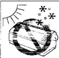
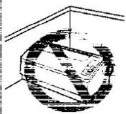
Do not use the printer under the following conditions to avoid machine malfunction.
natural_image
Illustration of a sun shining on a textured object with scattered asterisks (no text or symbols)- Extremely high or low temperature [temperature range: 10\~35°C (50\~95°F)]

natural_image
Illustration of a barrel with raindrops falling from above (no text or symbols)- Extremely high or low humidity (humidity range: 20–80% RH)

natural_image
Illustration of a cloud above a stylized book or document (no text or symbols visible)- Areas of high dust concentration
natural_image
Pure technical diagram of a mechanical component inside a circular housing (no text or symbols)- Areas of poor ventilation [a minimum of 4" (10 cm) clearance on all sides is necessary to insure proper ventilation]

natural_image
Illustration of a mechanical component with motion lines, no visible text or symbols- Areas with extreme vibration or when placed on an unstable, unlevel or leaned surface
Precautions
The following precautions are recommended to extend the life of the printer.

natural_image
Illustration of a laboratory setup with a glassware and three cylindrical containers (no text or symbols visible)- Keep all liquids away from the printer — Accidental spillage of a liquid into the printer can cause severe damage.

natural_image
Simple line drawing of a rectangular object resembling a printer or scanner (no text or symbols)- Do not operate the printer without paper and a ribbon cassette installed.
natural_image
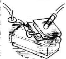
Hand-drawn sketch of a mechanical device with wires and components, no visible text or symbols- Do not place books, paper, or other items on top of the printer. - Do not obstruct the movement of the printhead while in operation.
natural_image
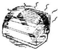
Illustration of a mechanical device emitting smoke or steam (no text or symbols)- Avoid prolonged use without allowing the printhead time to cool.

natural_image
Illustration of a hand inserting a plug into a battery (no text or symbols)- If the printer is not going to be used for an extended period, unplug the power cord.
Parts of the Printer


flowchart
graph TD
    A["④"] --> B["FONT"]
    C["⑤"] --> D["READY"]
    E["⑥"] --> F["LF/FF LOAD"]
    B --> G["TOF SET"]
    D --> G
    F --> G
    style A fill:#f9f,stroke:#333
    style C fill:#f9f,stroke:#333
    style E fill:#f9f,stroke:#333
    style B fill:#ccf,stroke:#333
    style D fill:#ccf,stroke:#333
    style F fill:#ccf,stroke:#333
    style G fill:#cfc,stroke:#333
    note right of G POWER PAPER OUT
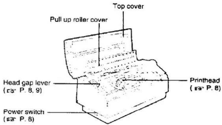
① FONT Switch ( P. 16)
② READY Switch
③ LF/FF Switch ( P. 16) LOAD Switch ( P. 16)
④ FONT indicators (P. 16)
⑤ READY indicator
⑥ POWER/PAPER OUT indicator ( P. 17)
7 Micro Line Feed/TOF SET ( P. 17)

Connecting to a Computer
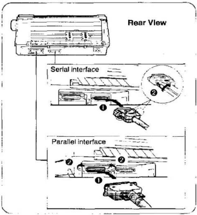
1 Turn the power off and unplug the power cord.
2 Attach other end of the interface cable from your computer.
Note:
• Take care not to drop the printer when you slant the printer to connect the cable.
- Use a shielded cable 6'5" {1.95 m} or less in length) for both of parallel and serial.
If you do not already have a interface cable, you will need to purchase one from your local computer store or dealer. For details, refer to "Interfacing" (P. 26).
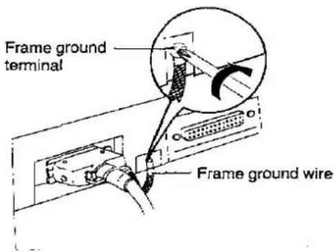
- If the cable has a frame ground wire, connect it to the frame ground terminal.
Power Supply
1 Connect the power cord firmly into the printer's power connector plug.

2 Plug the power cord into a grounded 3-prong AC socket.

Note:
Take care not to drop the printer when you
slant the printer to connect the power cord.
If the power cord is not connected firmly,
there is a fear of becoming hot.
Installing Ribbon Cassette
1 ① Turn the power on.
② Shift the head gap lever to position "6".

2 ① Raise the top cover.
② Raise the pull up roller cover.

3 Install the ribbon cassette and push 4 arrows down until they click into place.

Note:
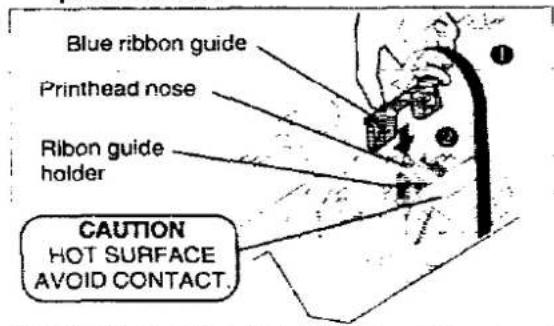
- Do not take off the blue ribbon guide from the ribbon.
4 ① Lift the blue ribbon guide from the ribbon cassette.
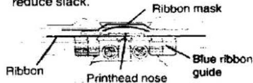
② Slide the blue ribbon guide between the printhead nose and the ribbon mask, and push it down.
Note:
- If the ribbon does not insert easily between the printhead nose and the ribbon mask, rotate the knob on the ribbon cassette to reduce slack.
5 Make sure the ribbon is not twisted and rotate the knob to remove any slack.

6 Close the pull up roller cover, then the top cover.
Note:
- If the top cover is replaced before the pull up roller cover, it may be damaged.
7 Adjust the head gap lever for the thickness of paper you are using.
| Position | Used for |
| 1 or 2 | Thinner sheets |
| 3, 4, 5 or 6 | Thick sheets ormulti-part forms |
Installing Paper
1 Remove the tape on the support bar.
② Grasp the tractor clamping levers and lift up to unlock tractors.
③ Slide the tractors to the approximate width of the paper being used.
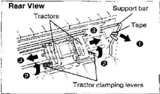
2 Open the tractor covers.

3 0 Be sure the support bar is in the raised position. Pass the paper between the support bar and the printer.
② Place the paper onto the tractor sprockets, making sure paper is aligned straight.
③ Close the tractor covers.

4 ① Push the support bar down until it clicks into place.
② Adjust the tractors to remove any slack.
③ Push the tractor clamping levers back to lock the tractors.

Note:
- When reinstalling paper, first raise the support bar by pushing both sides toward center and lifting the bar up. Pushing the support bar too strongly may cause the support bar to release from the printer.

5 Raise the paper stand.

Note:
• To lower the paper stand, pull it upward, then lower into place.
6 Turn the power on.
7 Adjust the head gap lever for the thickness of paper you are using ( P. 8).
8 Press LF/FF to load paper to the first print line.
Tearing off Paper
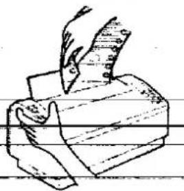
The printer is equipped with an AUTO TEAR OFF feature that automatically advances the paper's perforation to the tear off position when printing is completed. This feature has already been set to ON at the factory and will advance the paper 0.8 seconds after printing is completed. You can turn this feature OFF or change the wait time (0.4-10 Seconds) through the AUTO TEAR OFF item in the INSTALL menu of the Control Panel Software program (P. 13-14). ATUO TEAR OFF can also be turned OFF and ON through the Control Panel in the Initial Setup mode (P. 18).
Note:
- When you tear off the paper, be sure to hold the printer to avoid toter and fall.
natural_image
Illustration of a hand holding a sheet of paper over a wooden rolling pin (no text or symbols)Self Test
The printer has a self test feature which allows you to test the printer. When activated, this feature will print 5 lines of each resident font. When complete, it will return to the draft font and continue approximately 10 minutes.
1 Install the ribbon cassette and paper, then turn the power off ( P. 8-9).
2 While pressing FONT, turn the power on, then release.
3 Make sure all indicators are lit and press LF/FF LOAD
A sample printout will begin, which serves as a self test.
4 Once you see that the printer is functioning properly, you may turn the power off during the self test, or you may run the entire test. (approximately 10 minutes)
Printer Driver Selection
This procedure is the final step before printing and is performed in your application software program.
The steps will vary, depending on the software program. Consult your software package for proper procedures.
The Panasonic KX-P3200 will be your first choice. However, if the Panasonic KX-P3200 printer is not listed in your software, you must select an alternative from the following table.
Note: If using Microsoft Windows 3.1 or Windows 95, you will need to install a Windows printer driver. These drivers are located on the Setup Disk supplied with your printer. Proceed to Installing the Setup Disk on pages 11\~12 for the installation procedure.
Printer Selections (In order of priority)
| Panasonic KX-P3200 |
| Panasonic KX-P1150 |
| Panasonic KX-P2180 |
| Epson FX-850 |
| Panasonic KX-P1694 |
| Panasonic KX-P3696 |
| Panasonic KX-P1695 |
| Epson FX Series |
| IBM Proprinter III * |
* If selecting the IBM Proprinter III in your software, printer emulation must also be changed through the Control Panel Software program ( P. 13-14) or using the Control Panel ( P. 18).
Installing the Setup Disk
This Setup Disk can only be used in an IBM-PC or a compatible computer with a 3.5" floppy disk drive.
Before using the Setup Disk, it is recommended that you make a back-up copy and store the original in a safe place.
The following steps will automatically create a directory called 3200 and copy Control Panel Software and Command Reference utility from the Setup Disk to your C Drive. (You can change the directory and drive.)
For DOS
| Program | Function |
| Control Panel Software (CPS3200.EXE) | Allows you to view and change the printer settings on the computer screen. |
| Command Reference utility (CMDREF.EXE) | Allows you to access a detailed explanation of each software command on the computer screen. |
For installation, follow the steps below.
1 Insert the Setup Disk Into drive A or B.
3 Type SETUP and press Enter.
2 Type A: (or B:) and press Enter.
4 Follow the instructions on your computer screen.
For Windows 3.1
| Program | Function | |
| Printer Driver | A printer driver is the part of the software that allows the software to communicate with the printer via the interface in use. | |
| Control Panel Software |  | Allows you to view and change the printer settings on the computer screen. |
| Command Reference utility | Allows you to access a detailed explanation of each software command on the computer screen. | |
For installation, follow the steps below.
1 Start Windows 3.1
4 Click Run...
2 Insert the Setup Disk into drive A (or B).
5 Type A:\SETUP and then press Enter (or click OK).
3 Click File from the Program Manager window.
6 Follow the instructions on your computer screen.
For Windows 95
For Printer Driver
| Program | Function |
| Printer Driver | A printer driver is the part of the software that allows the software to communicate with the printer via the interface in use. |
Windows 95 Supports Plug & Play functions. When you turn on your computer, Windows recognizes and sets up your hardware automatically.
For installation, follow the steps below.
1 Connect interface cable to printer and computer, then power on printer.
2 Start computer using Windows 95.
3 When "New Hardware Found" dialog is displayed, click OK.
4 Insert the Setup Disk into drive A (or B).
5 Click:OK.
6 Select your Panasonic printer model.
7 Click OK to set up.
8 Select "Yes" and click Next.
9 Click Finish.
10 Follow the instructions on your computer screen.
For Utilities
| Program | Function | |
Control Panel Software  | Allows you to view and change the printer settings on the computer screen. | |
| Command Reference utility | Allows you to access a detailed explanation of each software command on the computer screen. | |
For installation, follow the steps below.
1 Start computer using Windows 95.
2 Click Start, point to "Run...".
3 Type A:\SETUP and then press Enter (or click OK).
4 Follow the instructions on your computer screen.
Note:
- If you cannot install the Printer Driver using Plug & Play, follow the steps below for installation.
1 Insert the Setup Disk into drive A.
2 Click Start, point to "Settings" and "Printers".
3 Double click Add Printer, and click Next.
4 When the option "Local printer" or "Network printer" appears, select Local printer then Next.
5 Click Have Disk, OK.
6 Select your Panasonic printer model.
7 Click Next.
8 Click Next to set up.
9 Select "Yes" and click Next.
10 Click Finish.
11 Follow the instructions on your computer screen.
Control Panel Software Program
The printer allows you to select 30 initial setup items shown in the table below by using the Control Panel Software program.
The printer has been factory set to operate with most of the popular software packages. If no changes are required, you should be ready to print. In most cases there will be no need to change the initial setup items.
You can verify the current settings by pressing F5 (P. 14) after running the Control Panel Software program. You can also verify the factory and current settings by turning the power on while pressing READY).
| Menu | Item | Menu | Item |
| PRINT STYLE | FONT | TEXTENHANCEMENT | BOLD |
| PITCH | DOUBLE HIGH | ||
| EMULATION | EMULATION | DOUBLE_STRIKE | |
| PAGEFORMAT | LINE/INCH | DOUBLE WIDE | |
| PAGE LENGTH | ITALICS | ||
| TOP MARGIN | ZERO FONT | ||
| BOTTOM MARGIN | CHARACTER SET | COUNTRY | |
| LEFT MARGIN | CHARACTER SET | ||
| RIGHT MARGIN | CODE PAGE | ||
| CTR PRINTHEAD | INSTALL | AUTO CR/IBM | |
| PRINT MODE | GRAPHIC DIRECTION | AUTO FEED XT CONTROL | |
| TEXT DIRECTION | AUTO LF | ||
| N.L.Q. DIRECTION | AUTO TEAR OFF | ||
| DOWNLOAD | |||
| PAPER OUT DETECT | |||
| SELECT 20CPI | |||
| T.O.F (Top of Form)SETTING | T.O.F. SETTING |
Note:
This program communicates between printer and computer. Before running this program under Windows 3.1 or Windows 95, be sure printing is completed.
To recall the programs, follow the steps below.
1* At your C:\prompt, type CD 3200 and press Enter.
2 Type CPS3200 and press Enter.
1 Select KX-P3200 Group.
2 Double click "Control Panel Software" icon.
1 Click Start, point to "Programs", "KX-P3200" "Control Panel Software".
2 Click "Control Panel Software".
* If you changed the directory when installing utilities to DOS, select your changed directory and press Enter
Using the Setup Disk
Note:
- If you want to run the Control Panel Software program using the Setup Disk, follow the steps below.
- Insert your Setup Disk into either drive A or B.
- ① Type A: (or B:) and press Enter.
● Type CD DOS and press Enter.
● Type CPS3200 and press Enter.
- Select Run from the File menu.
② Type A:\DOS\CPS3200 (or B:\DOS\CPS3200).
① Press Enter (or click OK).
- Click Start, point to Run and click it.
● Type A:\DOS\CPS3200 (or B:\DOS\CPS3200)
● Press Enter (or click OK)
3 The first screen is an introduction to the operation of the Control Panel Software program. Please read it through and press any key to continue. (If your display is monochrome, press "M" key.)
4 The
- When PAPER OUT DETECT is set to ON, printing stops at 0.5" from the bottom of the paper.
The paper out detector can be disabled through the Control Panel Software program ( P. 13).
Using the Control Panel and DIP Switch
Initial Setup Mode
The following features (items) can be set in the Initial Setup mode through the Control Panel; Emulation, Auto Line Feed, Auto Tear off, Graphic Direction, Page Length and Interface. Each time you press FONT, you will advance to the next item. Each time you press READY, the item's status will change. Select the desired setting according to the status of the indicators.
To enter the Initial Setup Mode
While pressing ! LF/FF LOAD , turn the power on. If paper is installed, the current setting will be printed.

flowchart
graph TD
    A["Initial Setup Mode"] --> B["FONT"]
    B --> C["FONT"]
    C --> D["READY"]
    D --> E["The current setting will be printed."]
    E --> F["Page Length"]
    F --> G["11" FONT READY 12" FONT READY 11 23" (11.65")"]
    F --> H["8.5" FONT READY 14" FONT READY 14""]
    F --> I["8" FONT READY 14" FONT READY 14""]
    F --> J["Page Length"]
    J --> K["Page Length"]
    K --> L["Page Length"]
    L --> M["Page Length"]
    M --> N["Page Length"]
    N --> O["Page Length"]
    O --> P["Page Length"]
    P --> Q["Page Length"]
    Q --> R["Page Length"]
    R --> S["Page Length"]
    S --> T["Page Length"]
    T --> U["Page Length"]
    U --> V["Page Length"]
    V --> W["Page Length"]
    W --> X["Page Length"]
    X --> Y["Page Length"]
    Y --> Z["Page Length"]
    Z --> AA["Page Length"]
    AA --> AB["Page Length"]
    AB --> AC["Page Length"]
    AC --> AD["Page Length"]
    AD --> AE["Page Length"]
    AE --> AF["Page Length"]
    AF --> AG["Page Length"]
    AG --> AH["Page Length"]
    AH --> AI["Page Length"]
    AI --> AJ["Page Length"]
    AJ --> AK["Page Length"]
    AK --> AL["Page Length"]
    AL --> AM["Page Length"]
    AM --> AN["Page Length"]
    AN --> AO["Page Length"]
    AO --> AP["Page Length"]
    AP --> AQ["Page Length"]
    AQ --> AR["Page Length"]
    AR --> AS["Page Length"]
    AS --> AT["Page Length"]
    AT --> AU["Page Length"]
    AU --> AV["Page Length"]
    AV --> AW["Page Length"]
    AW --> AX["Page Length"]
    AX --> AY["Page Length"]
    AY --> AZ["Page Length"]
    AZ --> BA["Page Length"]
    BA --> BB["Page Length"]
    BB --> BC["Page Length"]
    BC --> BD["Page Length"]
    BD --> BE["Page Length"]
    BE --> BF["Page Length"]
    BF --> BG["Page Length"]
    BG --> BH["Page Length"]
    BH --> BI["Page Length"]
    BI --> BJ["Page Length"]
    BJ --> BK["Page Length"]
    BK --> BL["Page Length"]
    BL --> BM["Page Length"]
    BM --> BN["Page Length"]
    BN --> BO["Page Length"]
    BO --> BP["Page Length"]
    BP --> BQ["Page Length"]
    BQ --> BR["Page Length"]
    BR --> BS["Page Length"]
    BS --> BT["Page Length"]
    BT --> BU["Page Length"]
    BU --> BV["Page Length"]
    BV --> BW["Page Length"]
To exit the Initial Setup Mode
Press LF/FF LOAD
If paper is installed, the current setting will be printed.
Returning All Current Settings to the Factory Settings
This procedure will reset ALL settings to the original factory settings.
This includes those settings made through the Control Panel Software program.
1 While pressing READY and FONT, turn the power on, then release.
2 Press READY.
Using the DIP Switch
The following serial interface items can be set by using the DIP switch; Baud Rate, Parity, Protocol, Data Length and Polarity. DIP switch is found on the bottom of the printer. Refer to the following charts to make any serial interface settings as necessary to match your computer system.
1 ① Turn the power off.
② Unplug the power cord and interface cable from the printer.
③ Carefully turn the printer over as shown.

Note:
Take care not to drop the printer and damage the covers when you set the DIP switches.

DIP Switch
Chart 1
| Switch | Funciton | ON | OFF |
| 1 | Baud Rate | Refer to Chart 2 | |
| 2 | |||
| 3 | |||
| 4 | Parity | Refer to Chart 3 | |
| 5 | |||
| 6 | Protocol | XON/XOFF | DTR |
| 7 | Data Length | 7 bit | 8 bit |
| 8 | Polarity | SPACE | MARK |
2 ① Slide the cover to the left.
② Move the DIP switches to the appropriate ON or OFF position.
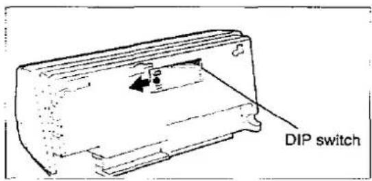
Chart 2
| Baud Rate\Switch | 1 | 2 | 3 |
| 19200 | ON | ON | ON |
| 9600 | OFF | OFF | OFF |
| 4800 | ON | OFF | OFF |
| 2400 | OFF | ON | OFF |
| 1200 | ON | ON | OFF |
| 600 | OFF | OFF | ON |
| 300 | ON | OFF | ON |
| 150 | OFF | ON | ON |
Chart 3
| Parity\Switch | 4 | 5 |
| None | OFF | OFF |
| Ignore | ON | OFF |
| Odd | OFF | ON |
| Even | ON | ON |

Factory Setting
Periodic Maintenance / Troubleshooting
Periodic Maintenance
The printer does not require routine maintenance. However, reasonable care of the printer will extend its life. The following periodic measures are recommended:
- Cleaning the unit is the most important action you can perform.
The frequency of cleaning is dependent upon the environment.
—Turn the power OFF and unplug the power cord.
— Clean the case and covers with a soft cloth. Use any mild commercial cleaner on the cloth, do not spray directly on to the printer.
— Raise the top cover and pull up roller cover. Vacuum or dust the inside area of the unit. Be very careful not to damage the printhead ribbon cable or the carriage drive belt.
— The platen should be cleaned with denatured alcohol only.
-- The carriage guide bar can be lubricated with a very light oil. Contact your Authorized Panasonic Service Center for advice on lubrication.
Ribbon Cassette
Note:
- if the ribbon begins to catch, snag, or tear from the printhead, your printer requires servicing.
Caution:
- The printhead may be hot, use caution when the cover is open.
Troubleshooting
Most problems associated with the printer can be traced to improper setup, installation, or cabling. The following table will assist you in identifying and correcting some of the more common problems. If you need additional help, contact the store from which the unit was purchased or the Panasonic technical support number found on the back cover of this manual.
| Symptom | Possible Cause | Probable Solution |
| Ink smears | Head gap lever is not in proper position | Move the lever toward the position “6” until ink doesn’t smear ( P. 8) |
| Printout is faint | Head gap lever is not in proper position | Adjust the lever to the proper position ( P. 8, 9) |
| Printhead moves but there is no printing | Ribbon is not installed correctly | Re-insert ribbon ( P. 8) |
| Paper out detector inoperative | PAPER OUT DETECT is OFF | Set PAPER OUT DETECT to ON ( P. 13) |
| Printer does not power up | No AC power | Check power cord ( P. 7) |
| Power is on but printer does not print | Printer is not READY | Press READY |
| Interface cable is not properly connected | Secure connection ( P. 7) | |
| Out of paper | Install new paper ( P. 9) | |
| Printhead has become overheated | Allow the printhead some time to cool down. The printer will automatically resume printing | |
| Wrong Interface setting is selected | Set interface setting to match the computer ( P. 18, 19) | |
| Carriage stops moving, all indicators start blinking | Path of printhead is blocked | Turn the power off, clear the path. Turn the power back on to resume printing |
| Unexpected characters appear in printing | EMULATION is set incorrectly | Check printer driver of your software package and set EMULATION accordingly ( P. 13, 18) |
(continued)
| Symptom | Possible Cause | Probable Solution |
| Fanfold paper is jamming | Paper is stuck on or under the platen | Remove jammed paper and reinstall paper correctly into tractors ( P. 9) |
| Remove the platen, clear the debris and clean the platen ( P. 22) | ||
| Printed paper is caught in the printer | Tear off the printed paper every one or two pages | |
Place the printer on the edge of the table and the paper under the table as shown in the illustration [Make sure the printed paper go outside the support bar ( P. 6)]  | ||
| 32K Buffer Chip option (KX-P44) is installed but cannot download | DOWNLOAD is OFF | Set DOWNLOAD to ON ( P. 13) |
| Printout is double-spaced | AUTO LF is ON | Set AUTO LF to OFF ( P. 13, 18) |
| Keeps printing on the same line | Computer is not sending a LF command | Set AUTO LF to ON ( P. 13, 18) |
| Wrong character set prints | Wrong character set is selected | Set the character set as required ( P. 13) |
| Cannot print ASCII characters with code above 127 | Data length is set incorrectly | Set data length as required ( P. 19) |
| When using serial interface, printer does not print or data loss occurs | Parallel interface is selected on your printer | Set interface setting to Auto or Serial ( P. 18) |
| Baud rate, Parity, Protocol or Data length does not match with the computer | Set Baud rate, Parity, Protocol and Data length to match the computer ( P. 19) | |
| Paper is not advanced automatically when printing is completed | Auto tear off, Page length, Top margin and Bottom margin are set incorrectly | Set Auto tear off to ON and set Page length, Top margin and Bottom margin to meet your software package ( P. 13) |
| A communication error occurs when running the CPS (Control Panel Software) in Windows 95 | Printer Driver of KX-P3200 is spooling the data sent from DOS | 1. Select "Printers" from "Settings" in Windows 952. Select "Properties" of the KX-P32003. Select "Port Settings" from "Details" and disable "Spool MS-DOS print jobs" by clicking off its check box |
Options and Supplies
| Description | Model Number |
| Ribbon Cassette | KX-P181 |
| 32 K Buffer Chip | KX-P44 |
These items are subject to change without notice.
roubleshooting
Platen Removal
This procedure is to allow easy access for removing jammed labels or paper.
Caution:
- If the printer has been operating, the printhead may be hot. Use caution or allow unit to cool before attempting removal of the platen.
1 Remove the platen knob by pulling straight out.
2 Raise the top cover.

① Release the latches on the pull up roller unit.
Remove the pull up roller unit by pulling straight up.

To release the platen bushings.
A ① Push the right platen bushing (gray) in and
② Rotate the platen bushing towards the front of the printer.
③ Slide the platen bushing inward along the platen shaft.
B ① Push the left platen bushing (gray) in and
② Rotate the platen bushing towards the front of the printer.
③ Slide the platen bushing inward along the platen shaft.
5 Remove the platen by lifting from the left side.
Platen Installation
1 Move the head gap lever to position "6".
2

Lower the platen into the openings of the chassis (right side first).
Note:
- Make sure the metal washer on the right side of the platen is on the outside of the chassis.
3

A Align the right platen bushing with the opening in the chassis and slide the bushing into the opening.
B Align the left platen bushing with the opening in the chassis and slide the bushing into the opening.
4 Rotate the platen bushings towards the rear of the printer until they latch into place.
5 Replace the pull up roller unit.
Note:
• Take care not to damage the cover when replacing the pull-up roller unit.
6 Replace the top cover.
7 Reinstall the platen knob.
Printer Specifications
| Power requirements: | Refer to the namepalte located on the rear of the printer. | |||
| Frequency: | ||||
| Current: | ||||
| Interface: | Centronics parallelRS-232C/Serial interface | |||
| Print fonts: | 3 Draft (Pica, Elite, Micron)4 Near Letter Quality (Roman, Sans Serif, Courier, Bold PS)2 High Speed Draft (Pica, Elite) | |||
| Software emulation: | Epson FX-850IBM Proprinter III | |||
| Buffer: | 12 K (standard), additional 32 K (optional KX-P44) | |||
| Character sets: | EPSON mode ONE Italic and 17 characters set tables15 International characters and LEGAL SetIBM mode 17 character set tables | |||
| Dot configuration: | 184 inch (0.3 mm) dot diameterDraftNLQHSDMatrix(Hor. × Ver.)9 × 918 × 188 × 9Dot pitch(Hor.)1/20" (0.21 mm)1/240" (0.11 mm)1/90" (0.28 mm)(Ver.)1/72" (0.35 mm)1/144" (0.18 mm)1/72" (0.35 mm) | |||
| Maximum number ofcharacters per line (cpl): | FontPrint line size: 8"Pica [10 cpi (character per inch)]80 cplElite (12 cpi)96 cpiMicron (15 cpi)120 cpiCompressed (17 cpi)137 cpiElite compressed (20 cpi)160 cpi | |||
| Printing speed [characters persecond (cps)]: | MicronElitePlcaDraft330 cps264 cps220 cpsNLQ44 cps53 cps44 cpsHSD317 cps264 cps | |||
| Printing direction: | Uni-directional / Bi-directional (user selectable) | |||
| Line feed time: | Approx. 90 msec [with 1⁄2 inch (4.2 mm) line feeding] | |||
| Paper feed: | Push tractor feed (with fanfold paper) | |||
| Operating environment: | Temperature: 10°C~35°C {50°F~95°F}Humidity: 20~80% RH (Please allow the printer to stabilize at room temperature withinthe operating temperature range before operation) | |||
| Power consumption: | Max — 90 WStand by — 10 WSelf Test — 60 W | |||
| Storage envlroment: | Temperature: -20°C~60°C (-4°F~140°F)Humidity: 10~90% RH | |||
| Head service life: | Approx. 200 million strokes in DRAFT mode | |||
| Ribbon: | Endless fabric ribbonBlack ribbon cassette KX-P181:Life expectancy (in DRAFT mode/rolling ASCII)Approx. 6 million characters | |||
| Detectors: | Paper out detectorOverheat detectorOverload detector | |||
| Dimensions: | 427 (W) × 215 (D) × 197 (H) mm {16.8" × 8.5" × 7.8"} | |||
| Mass (Weight): | Approx. 4.9 kg {10.8 lbs.) | |||
| CPU: | TOSHIBA CORPORATION TMP90C845F 16 MHz | |||
Paper Specifications
Paper which may be used with this unit must be within the specifications provided below.
Width: 4-10 inches (102-254 mm)
Quality and number of sheets:
| Type of paper | Sheets | Weight | |
| Ibs | g/m^2 | ||
| Fine-quality paper | 1 | 16~24 | 60~90 |
| Non-carbon | 2~5 | 11~14 (17*) | 41~53 (64*) |
| Multi-layered with carbon | 2 | 11~14 (17*) | 41~53 (64*) |
(* only for the last sheet)
Note:
To insure optimum print quality, 16\~22 lbs (60\~82.5 g/m ^2 ) is recommended for graphic printing.
• In multi-layered paper with carbon, the carbon is equivalent to a sheet of paper.
"Weight in pounds" represents the weight of 500 [17 × 22 inches (432 × 559 mm)] sheets.
The printer will handle multipart forms up to 0.014 inch (0.36 mm) thick. Up to 5 copies of 14 lb. chemical release paper can be used.
Printing Area

| A | 1"(25.4mm) |
| B | 0.7"(17.8mm) |
| C* | 0.33"(8.38mm) |
| D | 1"(25.4mm) |
* You can set the first print line at 0, however, 0.33" or more is recommended to insure optimum print quality.
A: The area near the paper perforations where the print quality may not be optimum.
B: The minimum distance between the sprockets and first printable character. (When the left tractor is set on the left end and the margin is set to 0.)
C: The area from the top edge of the paper to the top of the first printed character where the print quality may not be optimum.
D: The area from the bottom edge of the paper where the print quality may not be optimum.
ntertacing
This information should be provided to the company from which you are purchasing the Printer Cable to ensure the proper wiring of the cable.
Parallel Interfacing
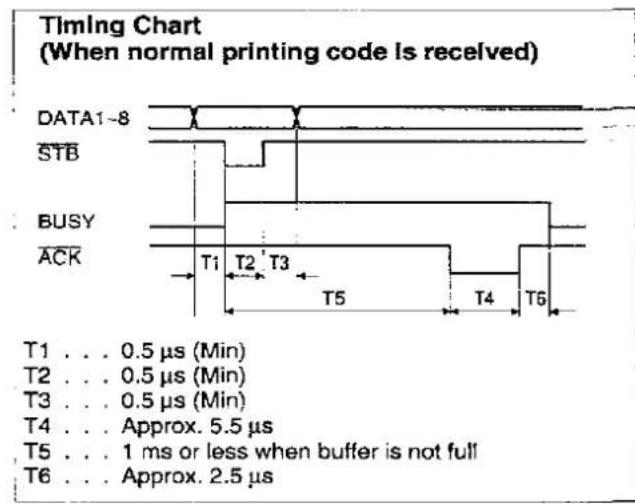
The parallel interface is a bidirectional parallel interface and it conforms to IEEE standard 1284-B.
A method of transferring data from a computer to a printer through a parallel interface based on the Centronics Standard.
Specifications:
• data transfer speed: 1000 cps minimum
- synchronization: external STROBE pulse
- logic levels: TTL (Transistor-Transistor-Logic) levels

Parallel Interface Connector (printer side)
Timing Diagram
- handshaking: BUSY and ACK signals
- connector type: 57-30360 (AMPHENOL) or equivalent
- cable: use a shielded cable 6'5" {1.95 m} or less in length.
| Signal pin | Return side pin | Signal | Direction |
| 1 | 19 | STB | Input |
| 2 | 20 | DATA 1 | |
| 3 | 21 | DATA 2 | |
| 4 | 22 | DATA 3 | |
| 5 | 23 | DATA 4 | |
| 6 | 24 | DATA 5 | |
| 7 | 25 | DTAT 6 | |
| 8 | 26 | DATA 7 | |
| 9 | 27 | DATA 8 | |
| 10 | 28 | ACK | Output |
| 11 | 29 | BUSY | |
| 12 | PO | ||
| 13 | SLCT | ||
| 14 | AUTO FEED XT | Input | |
| 15 | |||
| 16 | SG | ||
| 17 | FG | ||
| 18 | +5 V | Output | |
| 31 | 30 | PRIME | Input |
| 32 | ERROR | Output | |
| 33 | |||
| 34 | |||
| 35 | |||
| 36 | SLCT IN | Input |
Pin Configuration
Serial Interfacing
- cable: use a shielded cable 6'5" {1.95 m} or less in length.

Serial Interface Connector (printer side)
| Signal pin | Signal | Direction |
| 1 | FG | |
| 2 | TXD | OUTPUT |
| 3 | RXD | INPUT |
| 7 | SG | |
| 20 | DTR | OUTPUT |
Pin Configuration
A
Automatic Carriage Return (AUTO CR) ..... 13
Automatic Line Feed (AUTO LF) ..... 13, 18
B
Buffer 21,24
C
Cable 7
Centering (CTR PRINTHEAD) 13
Character sets 13,15
Code page 13
D
Data length 19
Detectors 17,24
Dot configuration 24
E
Emulation 13,18
F
Factory setting 14,19
Fanfold paper 9.25
Font 24
Form feed 16
Front panel switches .....6, 16, 17
G
Graphic direction 13,18
H
Head service life 24
1
Interfacing . . . . . . . . . . . . . . . . . . . . . . . . . . . . . . . . . . . . . . . . . . . . . . . . . . . . . . . . . . 7, 18, 26
Italics 13
L
Line feed 16
M
Maintenance 20
Margin 13
Micro line feed 17
N
Near Letter Quality (NLQ) 24
N.L.Q direction 13
O
Operating environment 5
Options 21
P
Page format 13
Page length 13
Paper installation 9
Paper specifications 25
Paper thickness 25
Parallel interface 7,26
Parts of the printer 6
Power requirement 24
Power switch 6,8
Print direction 13,24
Print speed 24
Print style 13
Printer driver 10.11.12
Printing area 25
Proportional Spacing (PS) 15
R
Reverse micro line feed 17
Ribbon cassette 2,8,20
S
Serial interface 7.26
Setup Disk 2,13
Command Reference program ..... 15
Control Panel Software program ..... 13
Printer driver 10, 11, 12
Specifications 24,25
T
Tear Off 10,13,18
Text direction 13
Top of Form (TOF) set 13.17
Troubleshooting 20
U
Unpacking 2
W
Windows printer driver 11,12
Z
Zero font 13
152
Matsushita Electric of Canada Limited
5770 Ambler Drive, Mississauga, Ontario, L4W 2T3
Matsushita Electric Industrial Co., Ltd.
Central P.O. Box 288, Osaka 530-91, Japan
- Operating Instructions
- Congratulations on purchasing a Panasonic printer.
- Warning:
- Caution:
- FOR YOUR SAFETY
- Unpacking
- Note:
- Warning/Caution
- Unpacking
- End-User License Agreement
- COPYRIGHT:
- LICENSE:
- TERM:
- LIMITED WARRANTY:
- LIMITATION OF LIABILITY:
- Operating Environment
- Precautions
- Parts of the Printer
- Connecting to a Computer
- Power Supply
- Installing Ribbon Cassette
- ① Turn the power on.
- ① Raise the top cover.
- Install the ribbon cassette and push 4 arrows down until they click into place.
- ① Lift the blue ribbon guide from the ribbon cassette.
- Make sure the ribbon is not twisted and rotate the knob to remove any slack.
- Close the pull up roller cover, then the top cover.
- Adjust the head gap lever for the thickness of paper you are using.
- Installing Paper
- Tearing off Paper
- Self Test
- Printer Driver Selection
- Installing the Setup Disk
- For Windows 95
- Control Panel Software Program
- Using the Setup Disk
- Command Reference Program
- For DOS>
- Using the Control Panel and DIP Switch
- Selecting a Character Font
- Line Feed/Form Feed (LF/FF)
- Paper Load (LOAD)
- Top of Form Function (TOF SET)
- Paper Out Detector
- Initial Setup Mode
- To enter the Initial Setup Mode
- To exit the Initial Setup Mode
- Returning All Current Settings to the Factory Settings
- Using the DIP Switch
- Periodic Maintenance / Troubleshooting
- Periodic Maintenance
- Ribbon Cassette
- Troubleshooting
- roubleshooting
- Platen Removal
- Platen Installation
- Move the head gap lever to position "6".
- 2
- 3
- Rotate the platen bushings towards the rear of the printer until they latch into place.
- Replace the pull up roller unit.
- Replace the top cover.
- Reinstall the platen knob.
- Paper Specifications
- Printing Area
- ntertacing
- Parallel Interfacing
- Specifications:
- Serial Interfacing
- A
- B
- C
- D
- E
- F
- G
- H
- 1
- L
- M
- N
- O
- P
- R
- S
- T
- U
- W
- Z
Marque : PANASONIC
Modèle : KX-P3200
Catégorie : Imprimante