
VN 750 - Moto KAWASAKI - Notice d'utilisation et mode d'emploi gratuit
Retrouvez gratuitement la notice de l'appareil VN 750 KAWASAKI au format PDF.


| Marque | Kawasaki |
| Modèle | VN 750 |
| Type de produit | Moto de type cruiser |
| Catégorie | Moto |
| Longueur (mm) | 2400 |
| Largeur (mm) | 900 |
| Hauteur (mm) | 1200 |
| Poids à vide (kg) | 230 |
| Capacité réservoir essence (L) | 15 |
| Moteur | Bicylindre en V, refroidissement liquide, 750 cm³ |
| Puissance (ch) | 65 |
| Démarreur | Électrique |
| Transmission | Chaîne, 5 vitesses |
| Freins avant | Double disque |
| Frein arrière | Disque simple |
| Pneu avant | 150/80-16 |
| Pneu arrière | 140/90-15 |
| Entretien courant | Vidange huile moteur, graissage chaîne, contrôle freins |
| Sécurité | Antivol de direction, béquille latérale |
| Pièces détachées | Disponibles chez concessionnaire agréé Kawasaki |
FOIRE AUX QUESTIONS - VN 750 KAWASAKI
Questions des utilisateurs sur VN 750 KAWASAKI
0 question sur cet appareil. Repondez a celles que vous connaissez ou posez la votre.
Poser une nouvelle question sur cet appareil
Téléchargez la notice de votre Moto au format PDF gratuitement ! Retrouvez votre notice VN 750 - KAWASAKI et reprennez votre appareil électronique en main. Sur cette page sont publiés tous les documents nécessaires à l'utilisation de votre appareil VN 750 de la marque KAWASAKI.
MODE D'EMPLOI VN 750 KAWASAKI

保存版
VN750
TWIN
Motorcycle Owner's Manual
AUSTRALIAN MODEL ONLY
TAMPERING WITH NOISE CONTROL SYSTEM
Owners are warned that the law may prohibit:
(a) The removal or rendering inoperative by any person other than for purposes of maintenance, repair or replacement, of any device or element of design incorporated into any new vehicle for the purpose of noise control prior to its sale or delivery to the ultimate purchaser or while it is in use; and
(b) the use of the vehicle after such device or element design has been removed or rendered inoperative by any person.
Whenever you see the symbols shown below, heed their instructions! Always follow safe operating and maintenance practices.
WARNING
○This warning symbol identifies special instructions or procedures which, if not correctly followed, could result in personal injury, or loss of life.
CAUTION
○This caution symbol identifies special instructions or procedures which, if not strictly observed, could result in damage to or destruction of equipment.
NOTE
○This note symbol indicates points of particular interest for more efficient and convenient operation.
NOTICE
THIS PRODUCT HAS BEEN MANUFACTURED FOR USE IN A REASONABLE AND PRUDENT MANNER BY A QUALIFIED OPERATOR AND AS A VEHICLE ONLY.
FOREWORD
We wish to thank you for choosing this fine Kawasaki Motorcycle. Your new motorcycle is the product of Kawasaki's advanced engineering, exhaustive testing, and continuous striving for superior reliability, safety, and performance.
Read this Owner's Manual before riding so you will be thoroughly familiar with the proper operation of your motorcycle's controls, its features, capabilities and limitations. This manual offers many safe riding tips, but its purpose is not to provide instruction in all the techniques and skills required to ride a motorcycle safely. Kawasaki strongly recommends that all operators of this vehicle enroll in a motorcycle rider training program to attain awareness of the mental and physical requirements necessary for safe motorcycle operation.
To ensure a long, trouble-free life for your motorcycle, give it the proper care and maintenance described in this manual. For those who would like more detailed information on their Kawasaki Motorcycle, a Service Manual is available for purchase from any Kawasaki Dealer. The Service Manual contains detailed disassembly and maintenance information.
Due to improvements in design and performance during production, in some cases there may be minor discrepancies between the actual vehicle and the illustrations and text in this manual.
KAWASAKI HEAVY INDUSTRIES, LTD. CONSUMER PRODUCTS & COMPONENTS GROUP
© Kawasaki Heavy Industries, Ltd., 1993
Feb. 1993. (1). (M)
TABLE OF CONTENTS
Specifications 4
Location of Parts 7
General Information 10
Meter Instruments 10
Speedometer and Tachometer...11
Coolant Temperature Gauge....11
Fuel Gauge. 12
Indicator Lights....12
Key 13
Ignition Switch/ Steering Lock .... 13
Right Handlebar Switches ..... 14
Engine Stop Switch....14
Starter Button....15
Headlight Switch ..... 15
Left Handlebar Switches....16
Dimmer Switch 16
Turn Signal Switch ..... 16
Horn Button....16
Passing Button. . . . . . . . . . . . . . 16
Fuel Tank Cap. 16
Fuel Tank 17
Fuel Tap 19
Stands 20
Document/Tool Kit Container 21
Seat 22
Helmet Hooks. 22
Electric Accessory Leads. 23
Break-In 25
How to Ride the Motorcycle ..... 26
Starting the Engine . . . . . . . . . . 26
Jump Starting 28
Moving Off. 30
Shifting Gears 31
Braking. 32
Stopping the Engine 33
Stopping the Motorcycle in an Emergency 34
Parking 35
Safe Operation 36
Daily Safety Checks 36
Additional Considerations for High Speed Operation ..... 38
Maintenance and Adjustment ..... 40
Periodic Maintenance Chart ..... 41
Engine Oil 44
Cooling System 48
Final Gear Case Oil 56
Spark Plugs 59
Air Cleaner. 60
Throttle Grip 62
Choke Lever. 64
Carburetors 66
Clutch 68
Brakes 70
Brake Light Switches ..... 75
Rear Shock Absorbers .....77
Wheels 81
Battery 85
Headlight Beam 87
Fuses 89
Fuel System 90
Cleaning 92
Storage 94
Wiring Diagram ..... Inside back cover
SPECIFICATIONS
PERFORMANCE
Maximum Horsepower
Maximum Torque
Minimum Turning Radius
DIMENSIONS
Overall Length
Overall Width
Overall Height
Wheelbase
Road Clearance
Dry Weight
ENGINE
Type
Displacement
Bore x Stroke
Compression Ratio
Starting System
Cylinder Numbering Method
44 kW (60PS) @7,500 r/min (rpm)
61N-m (6.2kg-m, 44.8 ft-lb) @5,500 r/min (rpm)
2.9 m (114.2 in)
2,300mm (90.55 in)
860 mm (33.9 in)
1,235 mm (48.62 in)
1,585 mm (62.40 in)
135 mm (5.31 in)
223 kg (492 lb)
DOHC,V type 2-cylinder,4-stroke,liquid-cooled
749 mL (45.7 cu in)
84.9×66.2mm(3.34×2.61in)
10.3 : 1
Electric Starter
Front to Rear, 1-2
Firing Order
Carburetors
Ignition System
Ignition Timing
(Electronically advanced)
Spark Plugs
Lubrication System
Engine Oil
Engine Oil Capacity
Coolant Capacity
TRANSMISSION
Transmission Type
Clutch Type
Driving System
Primary Reduction Ratio
Final Reduction Ratio
Overall Drive Ratio
Gear Ratio: 1st
2nd
3rd
4th
5th
Final Gear Case Oil
1-2
Keihin CVK34 x2
Battery and coil (transistorized ignition)
5° BTDC @1,100 r/min (rpm) —
25° BTDC @3,500 r/min (rpm)
NGK DPR7EA-9 or ND X22EPR-U9
Forced lubrication (wet sump)
SE or SF class SAE 10W40, 10W50, 20W40, or 20W50
4.0 L (4.2 US qt)
1.5 L (1.6 US qt)
5-speed, constant mesh, return shift
Wet, multi disc
Shaft drive
2.428(85/35)
2.454(15/22×36/10)
5.109 (Top gear)
2.250(36/16)
1.600(32/20)
1.230(32/26)
1.000(26/26)
0.857(24/28)
API GL-5 Hypoid gear oil SAE 90 [above 5°C(41°F)]
SAE 80 [below 5°C(41°F)]
Final Gear Case Oil Capacity
150 mL (0.16 US qt)
FRAME
Castor
Trail
Tire Size: Front
Rear
Fuel Tank Capacity
ELECTRICAL EQUIPMENT
Battery
Headlight
Tail/Brake Light
32°
127 mm (5.0 in)
100/90-19 57H Tubeless
150/90-15 M/C 74H or 150/90-B15 M/C 74H Tubeless
13.5 L (3.57 US gal)
12 V 14 Ah
12 V 60/55 W
12 V 5/21 W ×2
Specifications subject to change without notice, and may not apply to every country.
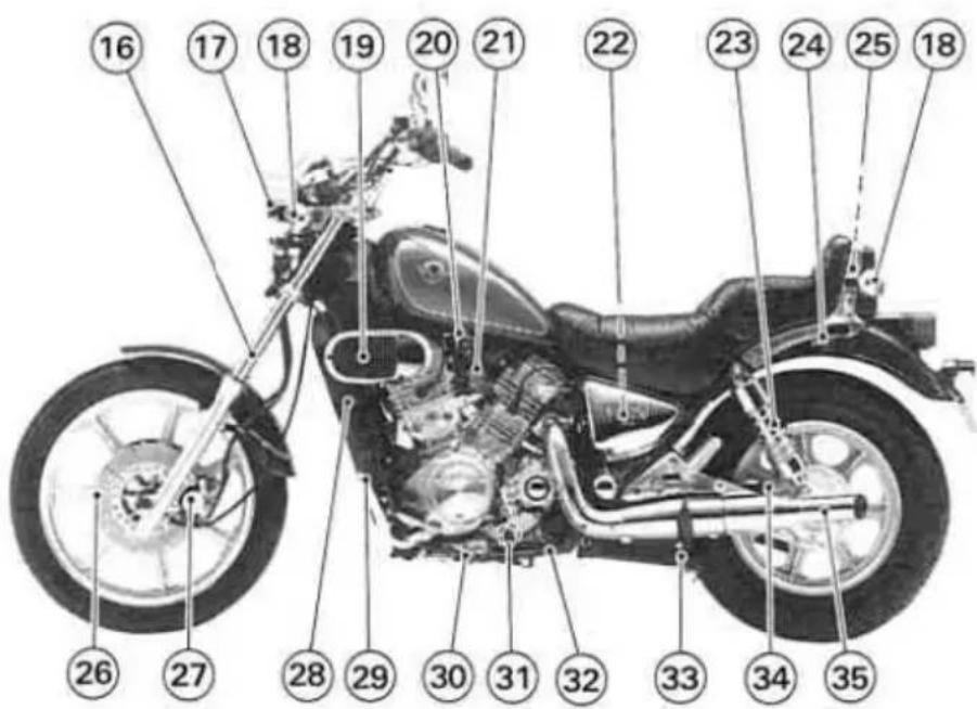
LOCATION OF PARTS

- Clutch Lever
- Passing Button
- Dimmer Switch
- Choke Lever
- Starter Lockout Switch
- Meter Instruments
- Brake Fluid Reservoir (Front)
- Engine Stop Switch
- Front Brake Lever
- Horn Button
- Turn Signal Switch
- Ignition Switch/Steering Lock
- Starter Button
- Headlight Switch
-
Throttle Grip
-
Front Fork
- Headlight
- Turn Signal Light
- Air Cleaner Element
- Fuel Tap
- Idle Adjusting Screw
- Fuse
- Rear Shock Absorber
- Helmet Hook
- Document/Tool Kit Container
- Brake Disc
- Brake Caliper
- Radiator
- Shift Pedal
- Side Stand Switch
- Oil Level Gauge
- Side Stand
- Center Stand
- Final Gear Case
- Muffler
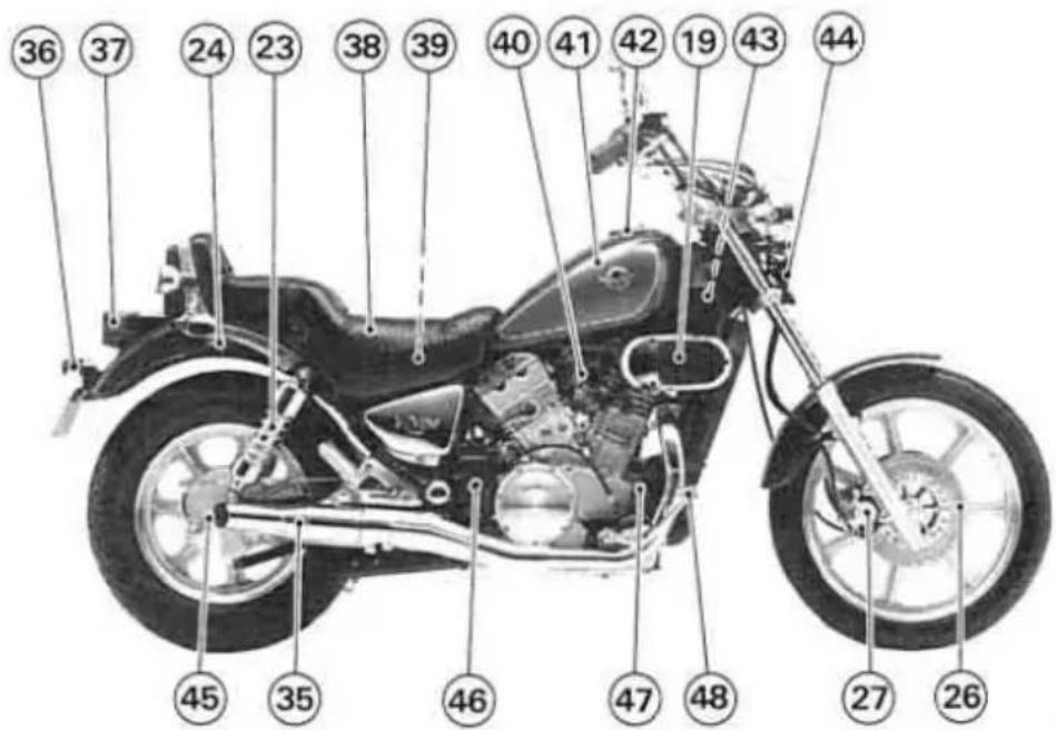
- License Plate Light
- Tail/Brake Light
- Seat
- Battery
- Carburetor
- Fuel Tank
- Fuel Tank Cap
- Radiator Cap
- Horn
- Brake Lining Wear Indicator
- Coolant Reserve Tank
- Rear Brake Light Switch
- Rear Brake Pedal
GENERAL INFORMATION
Meter Instruments
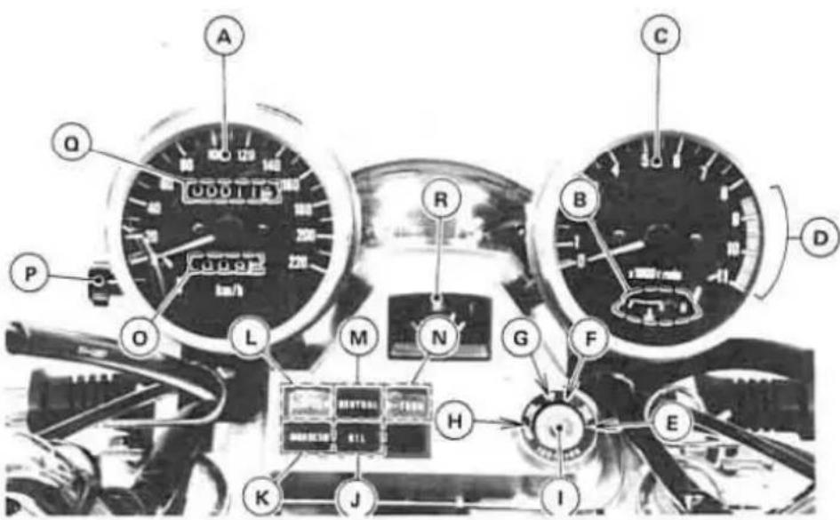
A. Speedometer
B. Coolant Temperature Gauge
C. Tachometer
D. Red Zone
E. P (Park) position
F. ON position
G. OFF position
H. LOCK position
I. Ignition Switch/Steering Lock
J. Oil Pressure Warning Light
K. High Beam Indicator Light
L. Left Turn Signal Indicator Light
M. Neutral Indicator Light
N. Right Turn Signal Indicator Light
O. Trip Meter
P. Reset Knob
Q. Odometer
R. Fuel Gauge
Speedometer and Tachometer
The speedometer shows the speed of the vehicle. In the speedometer face are the odometer and trip meter. The odometer shows the total distance that the vehicle has been ridden. The trip meter shows the distance traveled since it was last reset to zero. The trip meter can be reset to zero by turning the reset knob counterclockwise.
The tachometer shows the engine speed in the revolutions per minute (r/min, rpm). On the right side of the tachometer face is a portion called the "red zone". Engine r/min (rpm) in the red zone is above maximum recommended engine speed and is also above the range for good performance.
CAUTION
- Engine r/min (rpm) should not be allowed to enter the red zone; operation
in the red zone will overstress the engine and may cause serious engine damage.
Coolant Temperature Gauge
The coolant temperature gauge is in the tacometer face. This gauge shows the temperature of coolant. Ordinarily, the needle should stay within the white zone. If the needle reaches the red zone (marked "H"), stop the engine and check the coolant level in the reserve tank after the engine cools down.
CAUTION
- Do not let the engine continue running when the gauge needle reaches the red zone. Prolonged engine operation will result in severe damage from overheating.
Fuel Gauge
The fuel gauge shows the amount of fuel in the fuel tank. When the needle comes near the E(empty) position, turn the fuel tap to RES, and refuel at the earliest opportunity.
NOTE
○Make certain that the fuel tap is turned to ON (Not RES), after filling up the fuel tank.
Indicator Lights
TURN: When the turn signal switch is turned to left or right, the corresponding turn signal indicator light flashes on and off.
NEUTRAL: When the transmission is in neutral, the neutral indicator light is lit.
HIGH BEAM: When the headlight is on high beam, the high beam indicator light is lit.
OIL: The oil pressure warning light goes on whenever the oil pressure is dangerously low or the ignition switch is in the ON position with the engine not running, and goes off when the engine oil pressure is high enough. Refer to the Maintenance and Adjustment chapter for more detailed engine oil information.
Key
This motorcycle has a combination key, which is used for the ignition switch, steering lock, fuel tank cap, document/tool kit container, and helmet hook.
Blank keys are available at your Kawasaki Dealers. Ask your Dealer to make any additional spare keys you may need, using your original key as a master.
| OFF | Engine off. All electrical circuits off. |
| ON | Engine on. All electrical equipment can be used. |
| LOCK | Steering locked. Engine off. All electrical circuits off. |
| P(PARK) | Steering locked. Engine off. Taillight, city light, and license plate light on. All other electrical circuits cut off. |
NOTE
If you leave the PARK position on for a long time (one hour), the battery may become totally discharged.
Ignition Switch/Steering Lock
This is a four-position, key-operated switch. The key can be removed from the switch when it is in the OFF, LOCK, or P(PARK) position.
To operate the ignition switch:

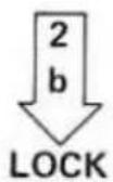
-
Turn the handlebar fully to the left.
-
a. For parking push down the key in the ON position and turn it to P (Park).
b. For locking push down the key in the OFF position and turn it to LOCK.
Right Handlebar Switches
Engine Stop Switch
In addition to the ignition switch, the engine stop switch must be in the RUN position for the motorcycle to operate.
The engine stop switch is for emergency use. If some emergency requires stopping the engine, move the engine stop switch to the OFF position.
NOTE
Although the engine stop switch stops the engine, it does not turn off all the electrical circuits. Ordinarily, the ignition switch should be used to stop the engine.
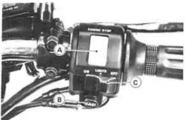
A. Engine Stop Switch
C. Headlight Switch
B. Starter Button
Starter Button
The starter button operates the electric starter when pushed in or the transmission in neutral.
Refer to the Starting the Engine section of the "How to Ride the Motorcycle" chapter for stating instructions.
Headlight Switch
| OFF | The headlight is off with the switch in the OFF position. |
| ○ | The city, tail, meter, and license plate lights come on if the switch is pushed to the ○ position with the ignition switch in the ON position. |
| ON | The head, city, tail, meter, and license plate lights come on if the switch is pushed forward to the ON position with the ignition switch in the ON position. |
Left Handlebar Switches
Dimmer Switch
High or low beam can be selected with the dimmer switch. When the headlight is on high beam (HI), the high beam indicator light is lit.

A. Dimmer Switch
C. Horn Button
B. Turn Signal Switch
D. Passing Button
Turn Signal Switch
When the turn signal switch is turned to L (left) or R (right), the corresponding turn signals flash on and off.
Horn Button
When the horn button is pushed, the horn sounds.
Passing Button
When the passing button is pushed, the headlight high beam (passing beam) comes on to signal the driver of the vehicle ahead that you are about to pass him. The passing light shuts off as soon as the switch is released.
Fuel Tank Cap
To open the fuel tank cap, insert the ignition switch key into the lock and turn the key to the right.
To close the cap, push it down into place with the key inserted. The key can be removed by turning it counterclockwise to the original position.
NOTE
- The tank cap cannot be closed without the key inserted, and the key cannot be removed unless the cap is locked properly.
Do not push the cap down with the key or the cap cannot be locked.
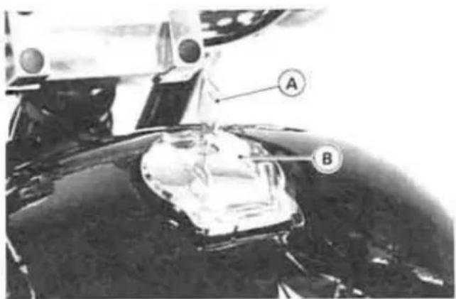
A. Ignition Switch Key
B. Fuel Tank Cap
Fuel Tank
Avoid filling the tank in the rain or where heavy dust is blowing so that the fuel does not get contaminated.

WARNING
○Gasoline is extremely flammable and can be explosive under certain conditions. Turn the ignition switch OFF.
Do not smoke. Make sure the area is well ventilated and free from any source of flame or sparks; this includes any appliance with a pilot light.
Never fill the tank so the fuel level rises into the filler neck. If the tank is overfilled, heat may cause the fuel to expand and overflow through the vents in the tank cap.
○After refueling, make sure the tank cap is closed securely.
○If gasoline is spilled on the fuel tank, wipe it off immediately.
Fuel Requirements:
Your Kawasaki engine is designed to use unleaded gasoline. However, except for Australian models, if suitable gasoline is not available then PREMIUM, SUPER, or FOUR-STAR gasolines may be used.
CAUTION
○Use of leaded gasoline is illegal in some countries, states or territories. Check local regulations before using leaded gasoline.
Octane Rating
The octane rating of a gasoline is a measure of its resistance to detonation or "knocking." The term commonly used to describe a gasoline's octane rating is the Research Octane Number (RON). Always use a gasoline with an octane rating equal to, or higher than, Research Octane Number (RON) 91.
NOTE
○If "knocking" or "pinging" occurs, use a different brand of gasoline or higher octane rating.
Fuel Tap
The fuel tap has three positions: OFF, ON, and RES (reserve). For normal operation turn the tap to the ON position. If the fuel runs out with the tap in the ON position, the last 1.8 L (0.48 US gal) of fuel can be used by turning the fuel tap to the RES position.

A. Fuel Tap
B. RES position
C. ON position
D. OFF position
With the fuel tap in the ON or RES position fuel flows to carburetors only when the engine is started or is running, and fuel supply is shut off when the engine is stopped.
Turn the fuel tap to the OFF position when the fuel tank is removed for maintenance and adjustments or the motorcycle is stored for a long time.
NOTE
○Since riding distance is limited when on RES, refuel at the earliest opportunity.
○Make certain that the fuel tap is turned to ON (Not RES) after filling up the fuel tank.
WARNING
- Practice operating the fuel tap with the motorcycle stopped. To prevent an accident you should be able to operate the fuel tap while riding without taking your eyes off the road.
Stands
The motorcycle is equipped with two stands: a center stand and a side stand.
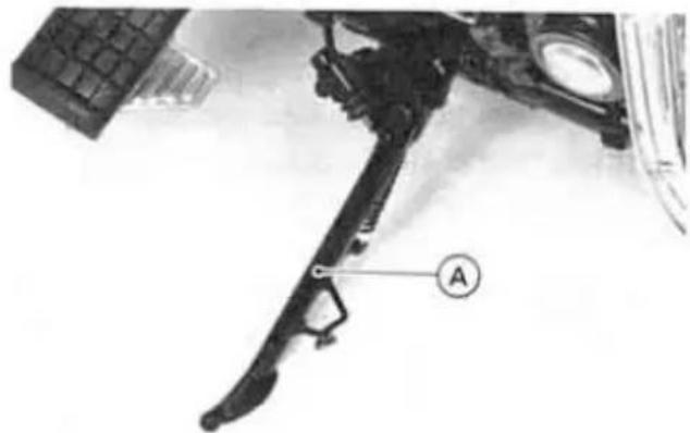
A. Side Stand
NOTE
When using the side stand, turn the handlebar to the left.
Whenever the side or center stand is used, make it a practice to kick the stand fully up before sitting on the motorcycle.
WARNING
○Forgetting and leaving the side stand down and riding away could cause an accident.
To set the motorcycle up on the center stand, step down firmly on the stand, and then lift the motorcycle up and to the rear using the grab rail as a handhold. Don't pull up on the seat to lift it as this will damage the seat.
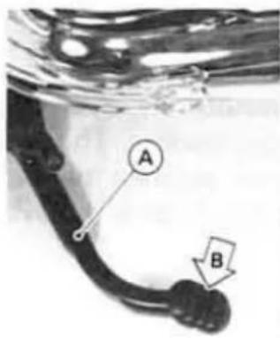
A. Center Stand
B. Step down

C. Grab Rail D. Lift up
Document/Tool Kit Container
Use this container to keep the owner's manual and any papers or documents which should be kept with the motorcycle, and tool kit with which minor adjustments and replacement of parts explained in this manual can be performed. To open the container, insert the ignition switch key into the container lock and turn it to the right.

A. Container Lock
B. Ignition Switch Key
Seat
Seat can be removed as follows.
- Open the document/tool kit conatiner.
- Remove the bolts from the seat mounting bracket, and lift the seat up and to the rear.

A. Bolts
Helmet Hooks
Helmets can be secured to the motor-cycle using the helmet hooks.
The helmet hook can be unlocked by inserting the ignition switch key into the lock, and turning the key to the right.
WARNING
Do not ride the motorcycle with helmets attached to the hooks. The helmets could cause an accident by distracting the operator or interfering with normal vehicle operation.

A. Helmet Hook

A. Helmet Hook
Electric Accessory Leads
The electric power of the battery can be used through the electric accessory leads regardless of ignition switch position. Observe and follow the notes listed below.
Electric Accessory Leads
| Location | Polarity | Lead Color |
| Inside Right Side Cover | (+) | White/Blue |
| (-) | Yellow/Black | |
| Inside Headlight Housing | (+) | White/Blue |
| (-) | Yellow/Black | |
| Maximum Current: 10A | ||
CAUTION
- Whenever you leave the motorcycle, stop using the electric accessories.
○Be careful not to discharge the battery
totally. For example, if a current of 20 amperes is continuously taken out with the engine stopped, even an originally-fully-charged battery may become totally discharged in about 20 minutes.
WARNING
Take care not to pinch any lead between the seat and the frame or between other parts to avoid a short circuit.
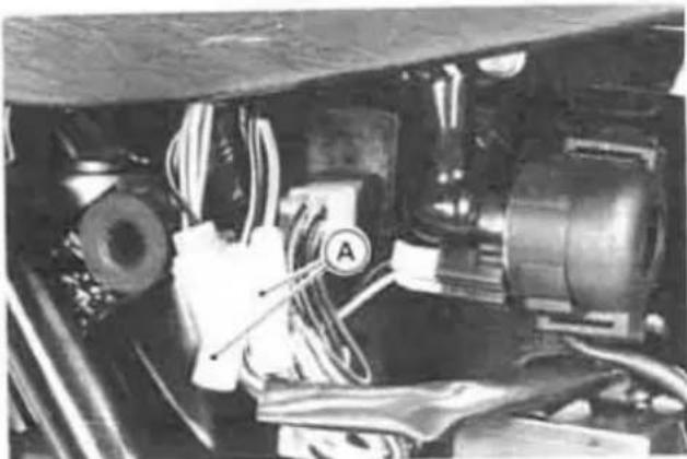
A. Electric Accessory Leads
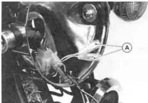
A. Electric Accessory Leads
BREAK-IN
The first 1,600 km (1,000 mi) that the motorcycle is ridden is designated as the break-in period. If the motorcycle is not used carefully during this period, you may very well end up with a "broken down" instead of a "broken in" motorcycle after a few thousand kilometers.
The following rules should be observed during the break-in period.
●The table shows maximum recommended engine speed during the break-in period.
| Distance traveled | Maximum engine speed |
| 0 ~ 800 km (0 ~ 500 mi) | 4,000 r/min (rpm) |
| 800 ~ 1,600 km (500 ~ 1,000 mi) | 6,000 r/min (rpm) |
- Do not start moving or race the engine immediately after starting it, even if the engine is already warm. Run the engine for two or three minutes at idle speed to give the oil a chance to work up into all the engine parts.
- Do not race the engine while the transmission is in neutral.
In addition to the above, at 800 km (500 mi) it is extremely important that the owner have the initial maintenance service performed by an authorized Kawasaki Dealer.
HOW TO RIDE THE MOTORCYCLE
Starting the Engine
●Turn the fuel tap to the ON position.
- Check that the engine stop switch is in the RUN position.
●Turn the ignition switch on.
●Make certain the transmission is in neutral or the clutch is disengaged.
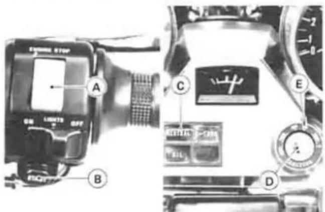
A. Engine Stop Switch
B. Starter Button
C. Neutral Indicator Light
D. Ignition Switch
E. ON position
- If the engine is cold, pull the choke lever all the way.
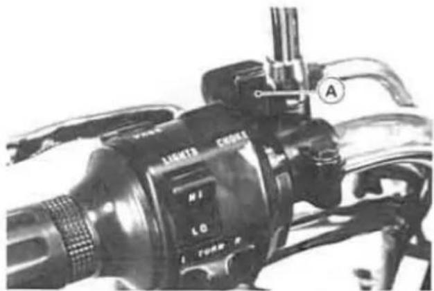
A. Choke Lever
NOTE
When the engine is already warm or on hot days [higher than 35°C (95°F)], open the throttle part way instead of using the choke, and then start the engine.
●Leaving the throttle completely closed, push the starter button with the clutch lever pulled in until the engine starts.
CAUTION
Do not operate the starter continuously for more than 5 seconds or the starter will overheat and the battery power will drop temporarily. Wait 15 seconds between each operation of the starter to let it cool and the battery power recover.
NOTE
- If the engine is flooded, crank the engine over with the throttle fully open until the engine starts.
The motorcycle is equipped with a starter lockout switch. This switch prevents the electric starter from operating when
the clutch is engaged and the transmission is not in neutral.
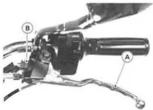
A. Clutch Lever
B. Starter Lockout Switch
●Gradually return the choke toward the off position a little at a time as necessary to keep the engine speed below 2,000 r/min (rpm) during warm-up.
- When the engine is warmed up enough to idle without using the choke, return the choke to the off position.
NOTE
○If you drive the motorcycle before the engine is warmed up, return the choke to the off position after you have driven the motorcycle for 15 seconds.
CAUTION
- Do not let the engine idle longer than five minutes, or engine overheating and damage may occur.
Jump Starting
If your motorcycle battery is "run down," it should be removed and charged. If this is not practical, a 12 volt booster battery and jumper cables may be used to start the engine.
WARNING
Battery acid generates hydrogen gas which is flammable and explosive under certain conditions. It is present within a battery at all times, even in a discharged condition. Keep all flames and sparks (cigarettes) away from the battery. Wear eye protection when working with a battery. In the event of battery acid contact with skin, eyes, or clothing, wash the affected areas immediately with water for at least five minutes. Seek medical attention.
Connecting Jumper Cables
●Make sure the ignition switch is turned "OFF"
- Connect a jumper cable from the positive (+) terminal of the booster battery to the positive (+) battery cable at the starter relay terminal.

A. Positive (+) Starter Relay Terminal
B. To Booster Battery Positive (+) Terminal
C. Unpainted Metal Surface
D. To Booster Battery Negative (−) Terminal
- Connect another jumper cable from the negative (−) terminal of the booster battery to your motorcycle rear brake pedal or other unpainted metal surface. Do not use the negative (−) terminal of the battery.
WARNING
Do not make this last connection at the carburetor or battery. Take care that you do not touch the positive and negative cables together, and do not lean over the battery when making this last connection. Do not jump start a frozen battery. It could explode.
- Do not reverse polarity by connecting positive (+) to negative (−) or a battery explosion and serious damage to the electrical system may occur.
●Follow the standard engine starting procedure.
CAUTION
Do not operate the starter continuously for more than 5 seconds or the starter will overheat and the battery power will drop temporarily. Wait 15 seconds between each operation of the starter to let it cool and the battery power recover.
●After the engine starts, disconnect the jumper cables. Disconnect the positive (+) cable from the motorcycle first.
Moving Off
- Check that the side stand is up.
●Pull in the clutch lever.
-Shift into 1st gear. - Open the throttle a little, and start to let out the clutch lever very slowly.
- As the clutch starts to engage, open the throttle a little more, giving the engine just enough fuel to keep it from stalling.
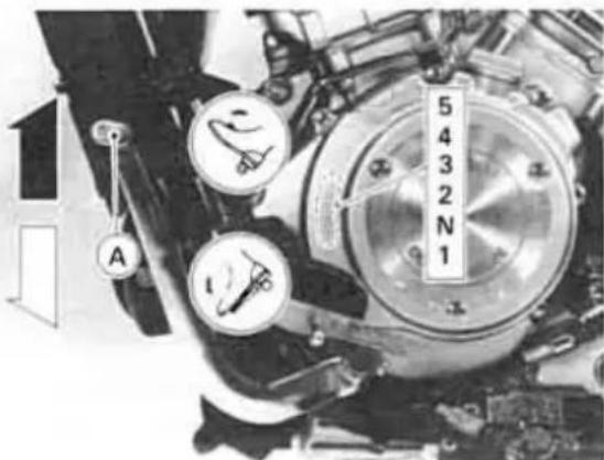
A. Shift Pedal
NOTE
The motorcycle is equipped with a side stand switch. This switch is designed so that the engine stops if the clutch is engaged with the transmission in gear when the side stand has been left down.
Shifting Gears
- Close the throttle while pulling in the clutch lever.
●Shift into the next higher or lower gear.
WARNING
When shifting down to a lower gear, do not shift at such a high speed that the engine r/min (rpm) jumps excessively. Not only can this cause engine damage, but the rear wheel may skid and cause an accident. Downshifting should be done below 5,000 r/min (rpm) for each gear.
- Open the throttle part way, while releasing the clutch lever.
NOTE
The transmission is equipped with a positive neutral finder. When the motorcycle is standing still, the transmission cannot be shifted past neutral from 1st gear. To use the positive neutral finder, shift down to 1st gear, then lift up on the shift pedal while standing still. The transmission will shift only into neutral.
Braking
- Close the throttle completely, leaving the clutch engaged (except when shifting gears) so that the engine will help slow down the motorcycle.
- Shift down one gear at a time so that you are in 1st gear when you come to a complete stop.
- When stopping, always apply both brakes at the same time. Normally the front brake should be applied a little more than the rear. Shift down or fully disengage the clutch as necessary to keep the engine from stalling.
●Never lock the brakes, or it will cause the tires to skid. When turning a corner, it is better not to brake at all. Reduce your speed before you get into the corner. - For emergency braking, disregard down-shifting, and concentrate on applying the brakes as hard as possible without skidding.

A. Front Brake Lever

A. Rear Brake Pedal
Stopping the Engine
- Close the throttle completely.
- Shift the transmission into neutral.
●Turn the ignition switch off.
●Support the motorcycle on a firm level surface with the side or center stand. - Lock the steering.
Stopping the Motorcycle in an Emergency
Your Kawasaki Motorcycle has been designed and manufactured to provide you optimum safety and convenience. However, in order to fully benefit from Kawasaki's safety engineering and craftsmanship, it is essential that you, the owner and operator, properly maintain your motorcycle and become thoroughly familiar with its operation. Improper maintenance and insufficient riding skills can create a dangerous situation known as throttle failure. Two of the most common causes of throttle failure are:
- During removal of the air cleaner by the owner, dirt is allowed to enter and jam the carburetor.
- A novice may forget which direction the throttle rotates; then jerk the throttle wide open thinking he has shut it off. He may panic when the machine accelerates suddenly instead of slowing
down; and "freeze," holding the throttle wide open.
In an emergency situation such as throttle failure, your motorcycle may be stopped by disengaging the clutch and applying the brakes. Once this stopping procedure is initiated, the engine stop switch may be used to stop the engine. If the engine stop switch is used, turn off the ignition switch after stopping the motorcycle.
Parking
- Shift the transmission into neutral and turn the ignition switch OFF.
●Support the motorcycle on a firm level surface with the side or center stand.
CAUTION
- Do not park on a soft or steeply inclined surface or the motorcycle may fall over.
- If parking inside a garage or other structure, be sure it is well ventilated and the motorcycle is not close to any source of flame or sparks; this includes any appliance with a pilot light.
WARNING
- Gasoline is extremely flammable and can be explosive under certain conditions.
●Lock the steering to help prevent theft.
NOTE
When stopping near traffic at night, you can leave the taillight and city light on for greater visibility by turning the ignition switch to the P (park) position.
Do not leave the switch at P position too long, or the battery will discharge.
SAFE OPERATION
Daily Safety Checks
Check the following items each day before you ride. The time required is minimal, and habitual performance of these checks will help ensure you a safe, reliable ride. If any irregularities are found during these checks, refer to the Maintenance and Adjustment chapter or see your dealer for the action required to return the motorcycle to a safe operating condition.
WARNING
- Failure to perform these checks every day before you ride may result in serious damage or a severe accident.
Fuel Adequate supply in tank, no leaks.
Engine oil . . . . . . . . . . . Oil level between level lines.
Tires... Air pressure (when cold)
| Front | 200 kPa (2.0 kg/cm 2 , 28 psi) | |
| Rear | Up to 97.5 kg(215 lb) load | 200 kPa(2.0 kg/cm 2 , 28 psi) |
| 97.5 ~ 184 kg(215 ~ 406 lb) load | 225 kPa(2.25 kg/cm 2 , 32 psi) | |
| Nuts, bolts, fasteners | Check that steering and suspension components, axles, and all controls are properly tightened or fastened. |
| Steering | Action smooth but not loose from lock to lock. No binding of control cables. |
| Brakes | No brake fluid leakage. |
| Brake pedal play 20~30 mm (0.8~1.2 in). | |
| Brake pad wear: Lining thickness more than 1 mm (0.04 in) left. | |
| Brake lining wear: Indicator within "USABLE RANGE". | |
| Throttle | Throttle grip play 2~3 mm (0.08~0.12 in). |
| Clutch | Clutch lever play 2~3 mm (0.08~0.12 in). |
| Clutch lever operates smoothly. | |
| Coolant | No coolant leakage. |
| Coolant level between level lines (when engine is cold). | |
| Radiator cap | Properly installed. |
| Final gear case | No oil leakage. |
| Electrical equipment | All lights and horn work. |
| Engine stop switch | Stops engine. |
| Side and center stands | Return to their fully up positions by spring tension. |
| Return springs not weak or not damaged. |
Additional Considerations for High Speed Operation
Brakes: The importance of the brakes, especially during high speed operation, cannot be overemphasized. Check to see that they are correctly adjusted and functioning properly.
Steering: Looseness in the steering can cause loss of control. Check to see that the handlebar turns freely but has no play.
Tires: High speed operation is hard on tires, and good tires are crucial for riding safety. Examine their overall condition, inflate to the proper pressure, and check the wheel balance.
Fuel: Have sufficient fuel for the high fuel consumption during high speed operation.
Engine Oil: To avoid seizure and resulting loss of control, make certain the oil level is at the upper level line.
Spark Plugs: For demanding operation such as racing, install one heat colder spark plugs NGK DPR8EA-9 or ND X24EPR-U9.
Coolant: To avoid overheating, check that the coolant level is at the upper level line.
Final Gear Case Oil: To avoid seizure and resulting loss of control, make certain the oil level is correct.
Electrical Equipment: Make certain that the headlight, tail/brake light, turn signals, horn, etc., all work properly.
Miscellaneous: Make certain that all nuts and bolts are tight and that all safety related parts are in good condition.
WARNING
○Handling characteristics of a motorcycle at high speeds may vary from those you are familiar with at legal highway speeds. Do not attempt high speed operation unless you have received sufficient training and have the required skills.
MAINTENANCE AND ADJUSTMENT
The maintenance and adjustments outlined in this chapter are easily carried out and must be done in accordance with the Periodic Maintenance Chart to keep the motorcycle in good running condition. The initial maintenance is vitally important and must not be neglected.
If you are in doubt as to any adjustment or vehicle operation, please ask your authorized Kawasaki Dealer to check the motorcycle.
Please note that Kawasaki cannot assume any responsibility for damage resulting from incorrect maintenance or improper adjustment done by the owner.
Periodic Maintenance Chart
| FrequencyOperation | Whichever comes first | * Odometer Reading km (mi) | |||||||
| 800(500) | 5,000(3,000) | 10,000(6,000) | 15,000(9,000) | 20,000(12,000) | 25,000(15,000) | 30,000(18,000) | See Page | ||
| Every | |||||||||
| Carburetor synchronization-check † | ● | ● | ● | ● | ● | ● | ● | 66 | |
| Idle speed-check † | ● | ● | ● | ● | ● | ● | ● | 66 | |
| Throttle grip play-check † | ● | ● | ● | ● | 62 | ||||
| Spark plug-clean and gap † | ● | ● | ● | ● | ● | ● | 59 | ||
| Air cleaner element-clean | ● | ● | ● | ● | 60 | ||||
| Air cleaner element-replace | 5 cleanings | ● | 60 | ||||||
| Fuel system-check |  | ● | ● | 92 | |||||
| Battery electrolyte level-check † | month | ● | ● | ● | ● | ● | ● | 87 | |
| Brake play-check † | ● | ● | ● | ● | ● | ● | ● | 73 | |
| Brake light switch-check † | ● | ● | ● | ● | ● | ● | ● | 75 | |
| Operation\Frequency | Whichever comes first | *Odometer Reading km (mi) | ||||||||
| Every | 800(500) | 5,000(3,000) | 10,000(6,000) | 15,000(9,000) | 20,000(12,000) | 25,000(15,000) | 30,000(18,000) | See Page | ||
| Brake lining or pad wear-check † | ● | ● | ● | ● | ● | ● | 70 | |||
| Brake fluid level-check † | month | ● | ● | ● | ● | ● | ● | ● | 71 | |
| K Brake fluid-change | 2 years | ● | 71 | |||||||
| Clutch-adjust | ● | ● | ● | ● | ● | ● | ● | 68 | ||
| K Steering-check † | ● | ● | ● | ● | ● | ● | ● | - | ||
| Final gear case oil level-check † | ● | ● | ● | 56 | ||||||
| Final gear case oil-change | ● | ● | 56 | |||||||
| K Propeller shaft joint-lubricate | ● | ● | - | |||||||
| K Nut, bolt, and fastener tightness -check † | ● | ● | ● | ● | - | |||||
| Tire wear-check † | ● | ● | ● | ● | ● | ● | 85 | |||
| Engine oil-change | year | ● | ● | ● | ● | 44 | ||||
| Oil filter-replace | ● | ● | ● | ● | 44 | |||||
| Oil screen-clean | ● | ● | ● | ● | 44 | |||||
| K General lubrication-perform | ● | ● | ● | ● | ● | ● | - | |||
| K Front fork oil-change | ● | - | ||||||||
| FrequencyOperation | Whichever comes first | *Odometer Reading km (mi) | ||||||||
| 800(500) | 5,000(3,000) | 10,000(6,000) | 15,000(9,000) | 20,000(12,000) | 25,000(15,000) | 30,000(18,000) | See Page | |||
| Every | ||||||||||
| K Swing arm pivot-lubricate | ● | ● | - | |||||||
| K Brake camshaft-lubricate | 2 years | ● | 71 | |||||||
| Coolant-change | 2 years | ● | 51 | |||||||
| Radiator hoses, connections-check † | year | ● | ● | ● | ● | 49 | ||||
| K Steering stem bearing-lubricate | 2 years | ● | - | |||||||
| K Master cylinder cup and dust seal-replace | 2 years | - | ||||||||
| K Caliper piston seal and dust seal-replace | 2 years | - | ||||||||
| K Brake cable-replace | 2 years | - | ||||||||
| K Brake hose-replace | 4 years | - | ||||||||
| K Fuel hose-replace | 4 years | - | ||||||||
K : Should be serviced by an authorized Kawasaki Dealer.
• For higher odometer readings, repeat at the frequency interval established here.
† : Replace, add, adjust, or torque if necessary.
Engine Oil
In order for the engine, transmission, and clutch to function properly, maintain the engine oil at the proper level, and change the oil and oil filter and clean the oil screen in accordance with the Periodic Maintenance Chart. Not only do dirt and metal particles collect in the oil, but the oil itself loses its lubricative quality if used too long.
WARNING
- Motorcycle operation with insufficient, deteriorated, or contaminated engine oil will cause accelerated wear and may result in engine or transmission seizure, accident, and injury.
Oil Level Inspection
- If the oil has just been changed, start the engine and run it for several minutes at idle speed. This fills the oil filter with oil. Stop the engine, then wait several minutes until the oil settles.
CAUTION
○Racing the engine before the oil reaches every part can cause engine seizure.
- If the motorcycle has just been used, wait several minutes for all the oil to drain down.
- Check the engine oil level through the oil level gauge. With the motorcycle held level, the oil level should come up between the lines next to the gauge.

A. Oil Filler Cap B. Oil Level Gauge
C. High Level
D. Low Level
- If the oil level is too high, remove the excess oil, using a syringe or some other suitable device.
- If the oil level is too low, add the correct amount of oil through the oil filler opening. Use the same type and brand of oil that is already in the engine.
CAUTION
If the engine oil gets extremely low or if the oil pump or oil passages clog up or otherwise do not function properly, the oil pressure warning light will light. If the light stays on when the engine speed is above 1,400 r/min (rpm), stop the engine immediately and find the cause.
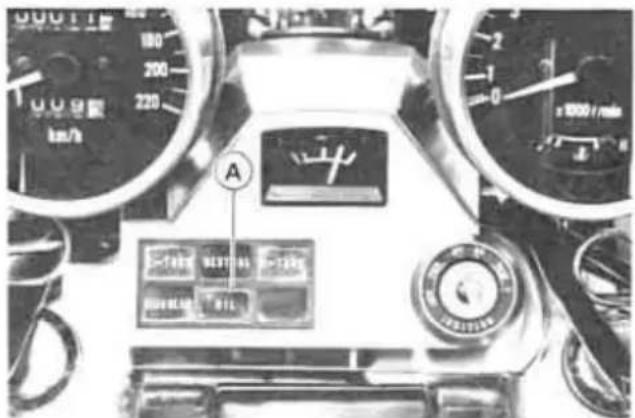
A. Oil Pressure Warning Light
Oil and/or Oil Filter Change, Oil Screen Cleaning
●Warm up the engine thoroughly, and then stop the engine.
- Place an oil pan beneath the engine drain plug.
- Remove the engine drain plug.

A. Drain Plug
- With the motorcycle held level, let the oil completely drain.
- If the oil filter is to be changed, remove the cartridge and replace it with a new one.
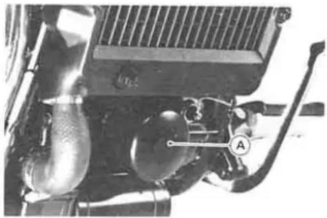
A. Cartridge
- Apply a thin film of oil on the gasket and tighten the cartridge to the specified torque.

A. Gasket

A. Oil Screen
- If the oil screen is to be cleaned, clean it in a bath of a high flash-point solvent. The oil screen is taken out when the drain plug is removed.
●Install the engine drain plug with its gasket and tighten it to the specified torque.
NOTE
○Replace the damaged gasket with a new one.
●Fill the engine up to the upper level with good quality motor oil specified in the table.
- Check the oil level.
- Start the engine and check for oil leakage.
Tightening Torque
Cartridge:
15\~20N-m
(1.5\~2.0 kg-m, 11.0\~14.5 ft-lb)
Engine Oil Drain Plug:
15\~20 N·m
(1.5\~2.0 kg-m, 11.0\~14.5 ft-lb)
Engine Oil
Grade: SE or SF class
Viscosity: SAE 10W40, 10W50, 20W40, or 20W50
Capacity: 3.6 L (3.8 US qt)
[when filter is not removed]
4.0 L (4.2 US qt)
[when filter is removed]
Cooling System
Radiator and Cooling Fan
Check the radiator fins for obstruction by insects or mud. Clean off any obstructions with a stream of low-pressure water.
WARNING
The cooling fan turns on automatically, even with the ignition switch off. Keep your hands and clothing away from the fan blades at all times.
CAUTION
○Using high-pressure water, as from a car wash facility, could damage the radiator fins and impair the radiator's effectiveness.
- Do not obstruct or deflect airflow through the radiator by installing
unauthorized accessories in front of the radiator or behind the cooling fan. Interference with the radiator airflow can lead to overheating and consequent engine damage.
Radiator Hoses:
Check the radiator hoses for cracks or deterioration, and connections for looseness in accordance with the Periodic Maintenance Chart.
Coolant
Coolant absorbs excessive heat from the engine and transfers it to the air at the radiator. If the coolant level becomes low, the engine overheats and may suffer severe damage. Check the coolant level each day before riding the motorcycle, and replenish coolant if the level is low. Change the coolant in accordance with the Periodic Maintenance Chart.
Information for Coolant:
To protect the cooling system (consisting of the aluminum engine and radiator) from rust and corrosion, the use of corrosion and rust inhibitor chemicals in the coolant is essential. If coolant containing corrosion and rust inhibitor chemicals is not used, over a period of time, the cooling system accumulates rust and scale in the water jacket and radiator. This will clog up the coolant passages, and considerably reduce the efficiency of the cooling system.
WARNING
- Use coolant containing corrosion inhibitors made specifically for aluminum engines and radiators in accordance with the instructions of the manufacturer. Chemicals are harmful to the human body.
Soft or distilled water must be used with the antifreeze (see below for antifreeze) in the cooling system.
CAUTION
- If hard water is used in the system, it causes scale accumulation in the water passages, and considerably reduces the efficiency of the cooling system.
If the lowest ambient temperature encountered falls below the freezing point of water, use permanent antifreeze in the coolant to protect the cooling system against engine and radiator freeze-up, as well as from rust and corrosion.
Use a permanent type of antifreeze (soft water and ethylene glycol plus corrosion and rust inhibitor chemicals for aluminum engines and radiators) in the cooling system. On the mixture ratio of coolant, choose the suitable one referring
to the relation between freezing point and strength directed on the container.
CAUTION
- Permanent types of antifreeze on the market have anti-corrosion and anti-rust properties. When it is diluted excessively, it loses its anti-corrosion property. Dilute a permanent type of antifreeze in accordance with the instructions of manufacturer.
NOTE
A permanent type of antifreeze is installed in the cooling system when shipped. It is colored green and contains ethylene glycol. It is mixed at 50% and has the freezing point of -35°C (-31°F).
Coolant Level Inspection
- Situate the motorcycle so that it is perpendicular to the ground (on its center stand).
- Check the coolant level through the coolant level gauge. The coolant level should be between the FULL and LOW marks.
NOTE
○Check the level when the engine is cold (room or atmospheric temperature).
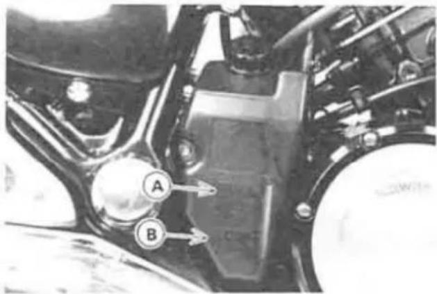
A. FULL Mark
B. LOW Mark
- If the amount of coolant is insufficient, unscrew the cap from the reserve tank, and add coolant through the filler opening to the FULL mark. Install the cap.
NOTE
In an emergency you can add water alone to the coolant reserve tank, however it must be returned to the correct mixture ratio by the addition of antifreeze concentrate as soon as possible.
CAUTION
If coolant must be added often, or the reserve tank completely runs dry, there is probably leakage in the system. Have the cooling system inspected by your authorized Kawasaki Dealer.
Coolant Change
WARNING
To avoid burns, do not remove the radiator cap or try to change the coolant when the engine is still hot. Wait until it cools down.
- Set the motorcycle up on its center stand.
- Remove the right front side cover.
- Place a container under the radiator drain plug, and drain the coolant from the radiator by removing the drain plug at the bottom of the radiator. Coolant begins to flow out when the plug is loosened several turns.
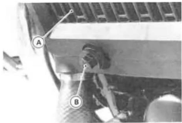
A. Radiator
B. Drain Plug
●Place a container under the water pump.
- Remove the drain plug at the bottom of the water pump.

A. Water Pump
B. Drain Plug
- Remove the radiator cap in two steps. First turn the cap counterclockwise to the first stop and wait there for a few seconds. Then push and turn it further in the same direction and remove the cap. This helps the coolant flow out more smoothly.
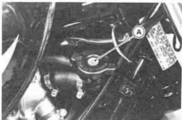
A. Radiator Cap

A. Drain Plug
●Coolant is drained from the radiator and engine. Immediately wipe off or wash out any spilled coolant on the frame, engine, or wheels.
WARNING
●Place a container under the drain plug on each cylinder and drain the coolant by removing the drain plugs respectively.
Coolant on tires will make them slippery and can cause an accident and injury.
- Visually inspect the old coolant. If whitish cotton-like wafts are observed, aluminum parts in the cooling system are corroded. A brownish color of the coolant indicates rusting of iron parts. If the coolant gives off an abnormal smell when changing, it may be caused by exhaust gas leaking into the cooling system (coolant leaks into engine). In this case, have the cooling system checked by your authorized Kawasaki Dealer.
●Pull off the air vent hose and unscrew the mounting bolt and remove the reserve tank from the grommet with lower hose attached.

A. Bolt
B. Reserve Tank
●Unscrew the cap off the reserve tank, and pour the coolant into a container. Install the reserve tank and its cap.
●Install the radiator, water pump, and cylinder drain plugs with the specified torques shown in the table. Always replace the O-ring and the gasket with new ones, if they are damaged.
Tighten Torque
Radiator Drain Plug:
3 N-m (0.3 kg-m, 26 in-lb)
Water Pump Drain Plug:
9 N-m (0.9 kg-m, 78 in-lb)
Cylinder Drain Plug:
9 N-m (0.9 kg-m, 78 in-lb)
- Fill the radiator up to the bottom of the radiator filler neck with coolant, and install the cap, turning it clockwise by about 1/4 turn.
NOTE
Pour in the coolant slowly so that it can expel the air from the engine and radiator.

A. Radiator Filler Neck
●Unscrew the cap off the reserve tank and fill it up to the FULL mark with coolant, and install the cap. Total refill will take about 1.5 L (1.6 US qt) after the air inside the system is expelled.
- Start the engine and warm it up by running it at idle speed, and then stop the engine.
- Remove the radiator cap and refill the radiator up to the bottom of the filler neck with coolant, if the coolant level has gone down.
- Check the coolant level in the reserve tank. Add coolant up to the FULL mark if the level has gone down.
- Inspect the drain plugs and the radiator cap for leaks.
Final Gear Case Oil
In order for the pinion and ring gears in the final gear case to function properly, check the oil level, and change the oil in accordance with the Periodic Maintenance Chart.
WARNING
- Motorcycle operation with insufficient, deteriorated, or contaminated oil causes accelerated wear and may result in seizure of the pinion and ring gears. Seizure can lock the rear wheel and skid the rear tire, with consequent loss of control.
Oil Level Inspection
●Put the motorcycle on its center stand.
- Remove the filler cap.
CAUTION
- Be careful not to allow any dirt or foreign materials to enter the gear case.
- Check the oil level. If it is insufficient, add oil as necessary. The oil level should come to the bottom thread of the filler opening.
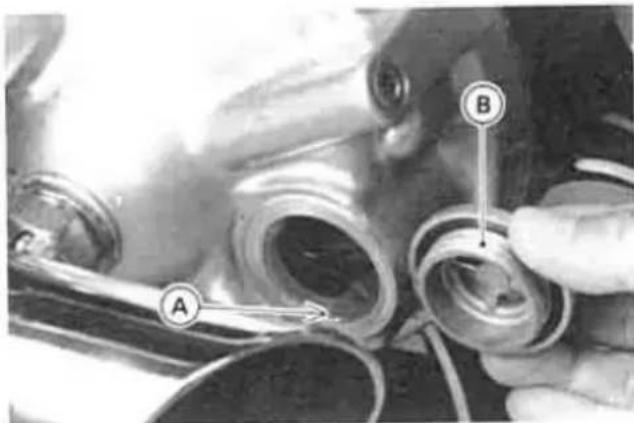
A. Bottom Thread
B. Filler Cap
NOTE
○Use the same type and brand of oil that is already in the final gear case.
Oil Change
NOTE
- Final gear case oil drains easily and picks up any sediment when the oil is warmed up by running the motorcycle.
●Put the motorcycle on its center stand.
●Place an oil pan beneath the gear case.
- Remove the filler cap and the drain plug.

A. Drain Plug
WARNING
When draining or filling the gear case, be careful that no oil gets on the tire and rim. Clean off any oil that inadvertently gets on them with soap and water.
●After the oil has completely drained out, install the drain plug and gasket.
Replace the damaged gasket with a new one.
●Fill the gear case up to the bottom thread of the filler opening with the oil specified below.
Final Gear Case Oil
| OilCapacity | about 150 mL(0.16 US qt) |
| OilType | API “GL-5”Hypoid gear oilabove 5°C ( 41°F ) SAE 90below 5°C ( 41°F ) SAE 80 |
NOTE
- "GL-5" indicates a quality and additive rating. "GL-6" rated hypoid gear oils can also be used.
●Install the filler cap.
Spark Plugs
The standard spark plug is shown in the table. The spark plugs should be taken out periodically in accordance with the Periodic Maintenance Chart for cleaning, inspection, and resetting of the plug gap.
Maintenance
If the plug is oily or has carbon built up on it, have it cleaned, preferably in a sand-blasting device, and then clean off any abrasive particles. The plug may also be cleaned using a high flash-point solvent and a wire brush or other suitable tool. Measure the gap with a wire-type thickness gauge, and adjust the gap if incorrect by bending the outer electrode. If the spark plug electrodes are corroded or damaged, or if the insulator is cracked, replace the plug. Use the standard plug.
Spark Plug
| Standard Plug | NGK DPR7EA-9 or ND X22EPR-U9 |
| Plug Gap | 0.8 ~ 0.9 mm(0.032 ~ 0.036 in) |
| Tightening Torque | 14 N·m(1.4 kg·m, 10.0 ft·lb) |

Air Cleaner
A clogged air cleaner restricts the engine's air intake, increasing fuel consumption, reducing engine power, and causing spark plug fouling.
The air cleaner element must be cleaned and replaced in accordance with the Periodic Maintenance Chart. In dusty areas, the element should be cleaned more frequently than the recommended interval. After riding through rain or on muddy roads, the element should be cleaned immediately. The element should be replaced if it is damaged.
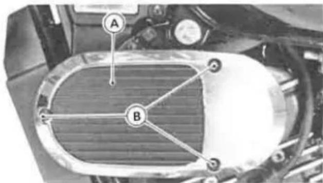
A. Air Cleaner Cover
B. Screws
Element Removal
- Remove the screws on the left and right air cleaner covers and then remove both the covers.
- Remove the bolts and pull out the element from both the air cleaner housings.

A. Bolts
B. Element
- Remove the element from the frame.
- Push a clean, lint-free towel into the air cleaner housing to keep dirt or other foreign material from entering.
- Inspect the element material and sponge gasket for damage. If any part of the element is damaged, the element must be replaced.
WARNING
If dirt or dust is allowed to pass through into the carburetors, the throttle may become stuck, possibly causing accident.
CAUTION
- If dirt gets through into the engine, excessive engine wear and possibly engine damage will occur.
NOTE
○Element installation is performed in the reverse order of removal.
Element Cleaning
●Clean the element in a bath of a high flash-point solvent.
- Dry the element with compressed air or squeeze it.
●After cleaning, saturate the element with SE class SAE 30 motor oil, squeeze out the excess, then wrap it in a clean rag and *squeeze it as dry as possible. Be careful not to tear the element.
WARNING
- Clean the element in a well ventilated area, and take care that there are no sparks or flame anywhere near the working area; this includes any appliance with a pilot light. Do not use gasoline or a low flash-point solvent to clean the element. A fire or explosion could result.
Throttle Grip
The throttle grip controls the throttle valves. If the throttle grip has excessive play due to either cable stretch or maladjustment, it will cause a delay in throttle response, especially at low engine speed. Also, the throttle valves may not open fully at full throttle. On the other hand, if the throttle grip has no play, the throttle will be hard to control, and the idle speed will be erratic. Check the throttle grip play periodically in accordance with the Periodic Maintenance Chart, and adjust the play if necessary.
Inspection
- Check that there is 2 \~ 3 mm (0.08 \~ 0.12 in) throttle grip play when lightly turning the throttle grip back and forth.
- If there is improper play, adjust it.
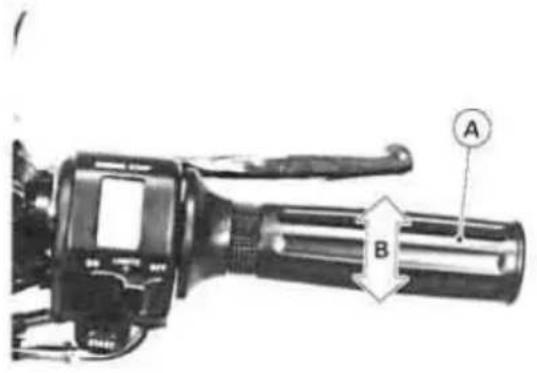
A. Throttle Grip
B. 2\~3 mm (0.08\~0.12 in)
Adjustment
- Loosen the locknuts, and screw both throttle cable adjusters in completely at the upper end of the throttle cables so as to give the throttle grip plenty of play.
●Turn out the decelerator cable adjuster until there is no play when the throttle grip is completely closed. Tighten the locknut.
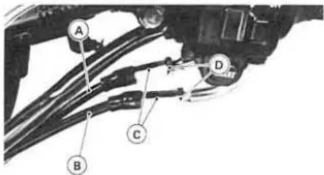
A. Accelerator Cable
B. Decelerator Cable
C. Adjusters
D. Locknuts
- Turn the accelerator cable adjuster until 2 \~ 3 mm (0.08 \~ 0.12 in) of throttle grip play is obtained. Tighten the lock-nut.
NOTE
- If the throttle cables cannot be adjusted by using the cable adjusters at the upper end of the throttle cables, have
them adjusted by an authorized Kawasaki Dealer.
Choke Lever
By pulling the choke lever, the carburetor provides a rich starting mixture that is necessary to enable easy starting when the engine is cold.
If starting difficulty or rich fuel mixture trouble occurs, inspect the choke lever, and adjust it if necessary.
Inspection
- Check that the choke lever returns properly and that the inner cable slides smoothly. If there is any irregularity, have the choke cable checked by an authorized Kawasaki Dealer.
●Push the choke lever back all the way to its released position.
●Determine the amount of choke cable play at the choke lever. Pull the choke lever until the starter plunger lever at the carburetor touches the starter plunger; the amount of choke lever travel is the amount of choke cable play.
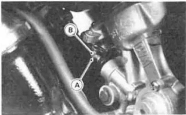
A. Starter Plunger Lever
B. Starter Plunger
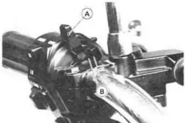
A. Choke Lever
B. 2\~3 mm (0.08\~0.12 in)
●The proper amount of play is 2 \~ 3 mm (0.08 \~ 0.12 in) at the bottom of the choke lever. If there is too much or too little play, adjust the choke cable.
Adjustment
- Loosen the locknut at the upper end of the choke cable, and turn the adjuster until the cable has the proper amount of play.
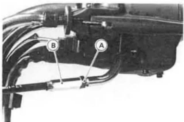
A. Locknut
B. Adjuster
●Tighten the locknut after adjustment.
Carburetors
The carburetor adjustments, idle speed and synchronization, should be performed in accordance with the Periodic Maintenance Chart or whenever the idle speed is disturbed.
The following procedure covers the idle speed adjustment. Carburetor synchronization should be done by your authorized Kawasaki Dealer.
NOTE
Poor carburetor synchronization will cause unstable idling, sluggish throttle response, and reduced engine power and performance.
Adjustment
- Start the engine, and warm it up thoroughly.
- Adjust the idle speed to 1,050 \~ 1,150 r/min (rpm) by turning the idle adjusting screw.

A. Idle Adjusting Screw
- Open and close the throttle a few times to make sure that the idle speed does not change. Readjust if necessary.
- With the engine idling, turn the handlebar to each side. If handlebar movement changes the idle speed, the throttle cables may be improperly adjusted or incorrectly routed, or they may be damaged. Be sure to correct any of these conditions before riding.
WARNING
Operation with damaged cables could result in an unsafe riding condition.
Clutch
Due to friction plate wear and clutch cable stretch over a long period of use, the clutch must be adjusted in accordance with the Periodic Maintenance Chart.
WARNING
To avoid a serious burn, never touch a hot engine or an exhaust pipe during clutch adjustment.
Inspection
- Check that the clutch lever has 2 3 mm (0.08 \~ 0.12 in) of play as shown in the figure.
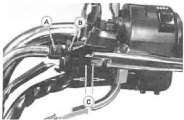
A. Adjuster
B. Locknut
C. 2\~3 mm (0.08\~0.12 in)
If it does not, adjust the lever play as follows.
Adjustment
- Loosen the locknut at the clutch lever.
- Turn the adjuster so that the clutch lever will have 2 3 mm (0.08 \~ 0.12 in) of play.
WARNING
- Be sure each end of the clutch outer cable is fully seated in its fitting, or it could slip into place later, creating enough cable play to prevent clutch disengagement, resulting in a hazardous riding condition.
●Tighten the locknut. - If it cannot be done, use the adjuster at the middle of the cable.

A. Locknut
B. Adjuster
NOTE
After the adjustment is made, start the engine and check that the clutch does not slip and that it releases properly.
- For minor corrections, use the adjuster at the clutch lever.
Brakes
Brake Wear Inspection
In accordance with the Periodic Maintenance Chart, inspect the brakes for wear. For the front disc brake caliper, if the thickness of either pad is less than 1 mm (0.04 in), replace both pads in the caliper as a set. Pad replacement should be done by an authorized Kawasaki Dealer.

On the rear brake panel is a brake lining wear indicator. If the brake lining wear indicator does not point within the USABLE RANGE when the brake is fully applied, the brake shoe linings have worn past the service limit. In this case, the brake shoes must be replaced and the drum and other brake parts examined by an authorized Kawasaki Dealer.
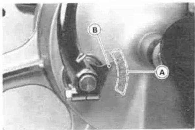
A. USABLE RANGE
B. Brake Lining Wear Indicator
Lubrication
In accordance with the Periodic Maintenance Chart, the brake camshaft should be lubricated by an authorized Kawasaki Dealer.
Disc Brake Fluid:
In accordance with the Periodic Maintenance Chart, inspect the brake fluid level in the reservoir and change the brake fluid. The brake fluid should also be changed if it becomes contaminated with dirt or water.
Fluid Requirement
Recommended fluids are given in the table below. If none of the recommended brake fluids are available, use extra heavy-duty brake fluid only from a container marked D.O.T.4.
Recommended Disc Brake Fluid
Castrol Girling-Universal Castrol GT (LMA) Castrol Disc Brake Fluid Check Shock Premium Heavy Duty
CAUTION
Do not spill brake fluid onto any painted surface.
Do not use fluid from a container that has been left open or that has been unsealed for a long time.
○Check for fluid leakage around the fittings.
○Check for brake hose damage.
Fluid Level Inspection
●The brake fluid level in the reservoir must be kept between the upper and lower level lines (reservoir held horizontal).
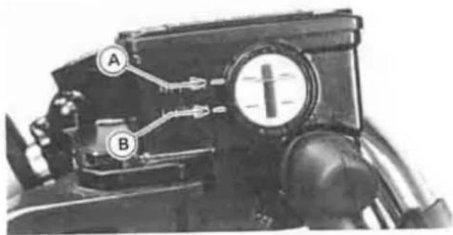
A. Upper Level
B. Lower Level
●Fill the reservoir to the upper level line.
WARNING
Do not mix two brands of fluid. Change the brake fluid in the brake line completely if the brake fluid must be refilled but the type and brand of the brake fluid that is already in the reservoir are unidentified.
Fluid Change
Have the brake fluid changed by an authorized Kawasaki Dealer.
Front Brake:
Disc and disc pad wear is automatically compensated for and has no effect on the brake lever action. So there are no parts that require adjustment on the front brake.
WARNING
If the brake lever feels mushy when it is applied, there might be air in the brake lines or the brake may be defective. Since it is dangerous to operate the motorcycle under such conditions, have the brake checked immediately by an authorized Kawasaki Dealer.
Rear Brake:
Brake pedal position can be adjusted to suit you. In accordance with the Periodic Maintenance Chart, inspect the brake pedal play.
Pedal Position Inspection
- When the brake pedal is in its rest position, it should be 55 \~ 65 mm (2.2 \~ 2.6 in) higher than the top of the footpeg.

A. Rear Brake Pedal
B. 55\~65 mm (2.2\~2.6 in)
- If it is not, adjust the pedal position.
Pedal Position Adjustment
- Loosen the locknut, and turn the adjusting bolt to adjust the pedal position.
●Tighten the locknut.
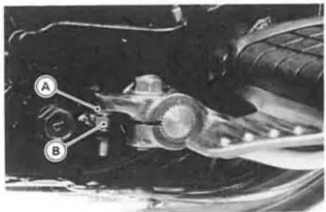
A. Adjusting Bolt
B. Locknut
- Check the brake pedal play and operation of the rear brake light switch.
Pedal Play Inspection
●The brake pedal should have 20 \~ 30 mm (0.8 \~ 1.2 in) of play when the pedal is pushed down lightly by hand.
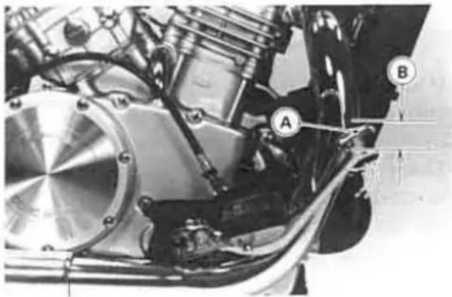
A. Rear Brake Pedal
B. 20\~30 mm (0.8\~1.2 in)
- Rotate the wheel to check for brake drag.
- Operate the pedal a few times to see that it returns to its rest position immediately upon release.
- Check braking effectiveness.
- If the pedal has improper play, adjust it.
Pedal Play Adjustment
●Turn the adjusting nut at the brake cam lever so that the pedal has 20 \~ 30 mm (0.8 \~ 1.2 in) of play.

A. Adjusting Nut
Brake Light Switches
When either the front or rear brake is applied, the brake light goes on. The front brake light switch requires no adjustment, but the rear brake light switch should be adjusted in accordance with the Periodic Maintenance Chart.
Inspection
●Turn on the ignition switch.
●The brake light should go on when the front brake is applied.
- If it does not, ask your authorized Kawasaki Dealer to inspect the front brake light switch.
- Check the operation of the rear brake light switch by depressing the brake pedal. The brake light should go on after about 15 mm (0.6 in) of pedal travel.
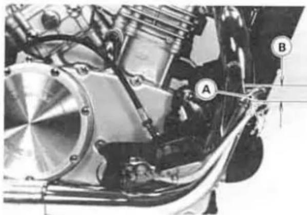
A. Rear Brake Pedal
B. 15 mm (0.6 in)
- If it does not, adjust the rear brake light switch.
Adjustment
- Adjust the rear brake light switch by moving the switch up or down. To change the switch position, turn the adjusting nut.
CAUTION
To avoid damaging the electrical connections inside the switch, be sure that the switch body does not turn during adjustment.

A. Rear Brake Light Switch
B. Adjusting Nut
C. Lights sooner
D. Lights later
Rear Shock Absorbers
The rear shock absorbers can be adjusted by changing the air pressure and damping force to suit various riding and loading conditions.
Before making any adjustments, however, read the following procedures:
Air Pressure
The air pressure in the rear shock absorbers can be adjusted for different road and loading conditions.
The following table shows an example of air pressure adjustment. To obtain stable handling and a suitable ride, adjust the air pressure as indicated. The standard air pressure for an average-build rider of 68 kg (150 lb) with no passenger and no accessories is atmospheric pressure. Ordinarily, the heavier the total load becomes, the higher the air pressure should be set.
Air Pressure Adjustment
| Air Pressure | Setting | Load | Road |
| Atmospheric Pressure 300 kPa(3.0 kg/cm2, 43 psi) | Soft Hard | Light Heavy | Good Bad |
To adjust the air pressure:
NOTE
○Check and adjust the air pressure when the rear shock absorbers are cold (room temperature).
●Put the motorcycle up on its center stand to raise the rear wheel off the ground.
●Take off the air valve caps on the left and right shock absorbers.
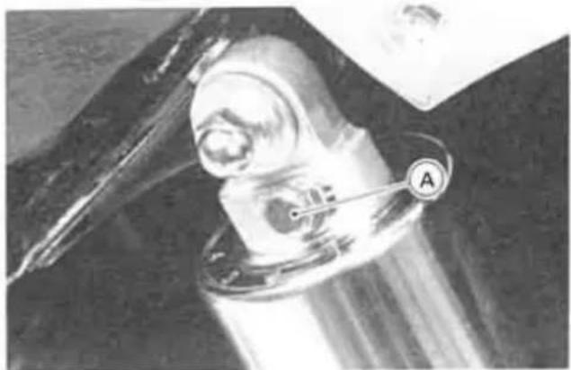
A. Air Valve
- Check the air pressure with the air pressure gauge.
NOTE
Do not use tire gauges for checking air pressure. They may not indicate the correct air pressure because of air leaks that occur when the gauge is applied to the valve.
●To lower the air pressure, push the valve core in slightly. To raise the pressure, inject air through the valve with a tire pump. Change the air pressure within the range specified in the preceding table to suit various riding conditions.
CAUTION
- Inject air little by little so that air pressure does not rise rapidly. Air pressure exceeding 500 kPa (5.0 kg/cm 2 , 71 psi) may damage the oil seal.
○Try to set the air pressure of the left and right shock absorbers as equally as possible.
WARNING
- Be sure to adjust the air pressure within the usable range. Pressure too high can produce a hazardous riding condition.
○Only air or nitrogen gas can be used. Never inject oxygen or any kind of explosive gas.
Do not incinerate the rear shock absorber.

A. Damping Adjuster
B. Number
Damping Force
The adjuster on each rear shock absorber has 4 positions so that the rebound damping force can be adjusted for different road and loading conditions. The numbers on the adjuster show the setting position.
The following table shows an example of damping force adjustment. To obtain stable handling and a suitable ride, adjust the damping force as indicated. The damping force can be left soft for average riding. But it should be adjusted harder for high speed riding or riding with a passenger. If the damping feels too soft or too stiff, adjust it in accordance with the following table.
The standard setting position under the same conditions as in air pressure adjustment is No. 2.
To adjust the damping force:
●Turn the adjusters to the desired position until you feel a click.
- Check to see that both adjusters are turned to the same relative position.
WARNING
If both damping adjusters are not adjusted equally, handling may be impaired and a hazardous condition may result.
Rebound Damping Adjustment
| Adjuster Position | Damping Force | Setting | Load | Road | Speed |
| 1 |  Stronger Stronger | Soft Hard Hard | Light Heavy Heavy | Good Bad Bad | Low[7DSW]High |
| 2 | |||||
| 3 | |||||
| 4 |
Wheels
Tubeless tires are installed on the wheels of this motorcycle. The indications of TUBELESS on the tire side wall and the rim show that the tire and rim are speci 'ly designed for tubeless use.

A. TUBELESS Mark
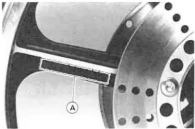
A. TUBELESS Mark
The tire and rim form a leakproof unit by making airtight contacts at the tire chamfers and the rim flanges instead of using an inner tube.
WARNING
- The tires, rims, and air valves on this motorcycle are designed only for
tubeless type wheels. The recommended standard tires, rims, and air valves must be used for replacement.
Do not install tube-type tires on tubeless rims. The beads may not seat properly on the rim causing tire deflation.
Do not install a tube inside a tubeless tire. Excessive heat build-up may damage the tube causing tire deflation.
Tires:
Payload and Tire Pressure
Failure to maintain proper inflation pressures or observe payload limits for your tires may adversely affect handling and performance of your motorcycle and can result in loss of control. The maximum recommended load in addition to vehicle weight is 184 kg (406 lb), including rider, passenger, baggage and accessories.
- Check the tire pressure often, using an accurate gauge.
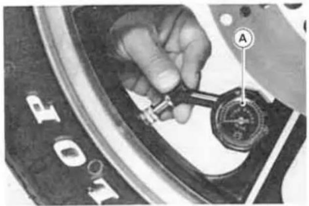
A. Tire Pressure Gauge
NOTE
○Measure the tire pressure when the tires are cold (that is, when the motorcycle has not been ridden more than a mile during the past 3 hours).
○Tire pressure is affected by changes in ambient temperature and altitude, and so the tire pressure should be checked
and adjusted when your riding involves wide variations in temperature or altitude.
Air Pressure (when cold)
| Front | 200 kPa (2.0 kg/cm 2 , 28 psi) | |
| Rear | Up to 97.5 kg(215 lb) load | 200 kPa (2.0kg/cm 2 , 28 psi) |
| 97.5 ~ 184 kg(215 ~ 406 lb)load | 225 kPa (2.25kg/cm 2 , 32 psi) | |
Tire Wear, Damage
As the tire tread wears down, the tire becomes more susceptible to puncture and failure. An accepted estimate is that 90% of all tire failures occur during the last 10% of tread life (90% worn). So it is false economy and unsafe to use the tires until they are bald.
- In accordance with the Periodic Maintenance Chart, measure the depth of the tread with a depth gauge, and replace any tire that has worn down to the minimum allowable tread depth.
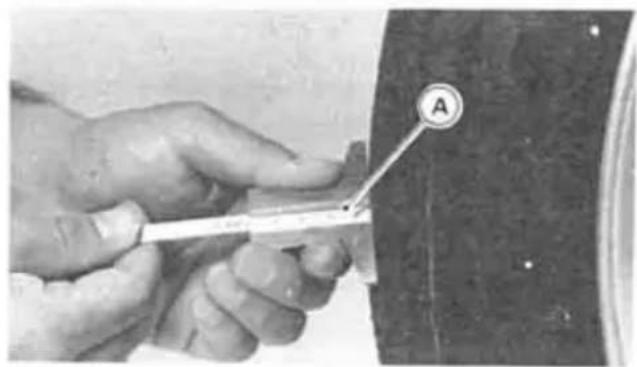
A. Tire Depth Gauge
Minimum Tread Depth
| Front | 1 mm (0.04 in) |
| Rear | 2 mm (0.08 in) |
●Visually inspect the tire for cracks and cuts, replacing the tire in case of bad damage. Swelling or high spots indicate
internal damage, requiring tire replacement.
- Remove any imbedded stones or other foreign particles from the tread.
NOTE
- Have the wheel balance inspected whenever a new tire is installed.
WARNING
To ensure safe handling and stability, use only the recommended standard tires for replacement, inflated to the standard pressure.
Tires that have been punctured and repaired do not have the same capabilities as undamaged tires. Do not exceed 100 km/h (60 mph) within 24 hours after repair, and 180 km/h (110 mph) at any time after that.
Standard Tire
| Front | 100/90-19 57HDUNLOP F11G orMETZELERMARATHON FRONTTubeless |
| Rear | 150/90-15 M/C 74HDUNLOP K425G or150/90-B15 M/C 74H METZELER ME88MARATHON EUROTubeless |
WARNING
- Use the same manufacturer's tires on both front and rear wheels.
Battery
Battery Electrolyte Level Inspection
The battery electrolyte level must be kept between the upper and lower level lines. Check the electrolyte level in each cell in accordance with the Periodic Maintenance Chart.
- Remove the battery from the motorcycle (See Battery Removal).
- Check that the electrolyte level in each cell is between the upper and lower level lines.

A. Filler Cap
C. Lower Level
B. Upper Level
- If the electrolyte level is low in any cell, fill with distilled water as follows.
- Remove the battery filler caps and fill with distilled water until the electrolyte level in each cell reaches the upper-level line.
CAUTION
- Add only distilled water to the battery. Ordinary tap water is not a substitute
for distilled water and will shorten the life of the battery.
Battery Removal
- Remove the seat.
●Unscrew the battery holder.

A. Battery Holder
B. Screw
- Disconnect the leads from the battery, first from the (−) terminal and then the (+) terminal.

A. (+) Terminal
B. (−) Terminal
●Take the battery out of the case.
- Clean the battery using a solution of baking soda and water. Be sure that the lead connections are clean.
Battery Installation
- Check that the battery case rubber dampers are properly in place.
●Put the battery in the battery case, and route the battery vent hose as shown on the caution label.
- Connect the capped lead to the (+) terminal, and then connect the black lead to the (−) terminal.
- Put a light coat of grease on the terminals to prevent corrosion.
- Cover the (+) terminal with its protective cap.
CAUTION
Make sure the battery vent hose is kept away from the drive system and exhaust system. Battery electrolyte can corrode and dangerously weaken the drive system. Do not let the vent hose become folded, pinched, or melted by the exhaust system. An unvented battery will not keep a charge and it may crack from built-up gas pressure.
Headlight Beam
Horizontal Adjustment
The headlight beam is adjustable horizontally. If not properly adjusted horizontally, the beam will point to one side rather than straight ahead.
●Turn the adjusting screw on the head-light rim in or out until the beam points straight ahead.

A. Adjusting Screw
Vertical Adjustment
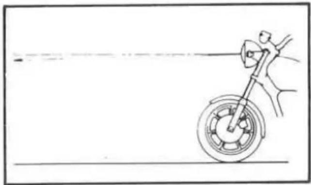
The headlight beam is adjustable vertically. If adjusted too low, neither low nor high beam will illuminate the road far enough ahead. If adjusted too high, the high beam will fail to illuminate the road close ahead, and the low beam will blind oncoming drivers.
●Push the headlight up or down to adjust the headlight vertically.
- If it is difficult, remove the mounting screws, and drop out the headlight unit.

A. Mounting Screw
●Loosen the headlight housing mounting nuts, and adjust the headlight vertically.

A. Mounting Nut
●Tighten the headlight housing mounting nuts.
●Install the headlight unit, and tighten the mounting screws.
NOTE
On high beam, the brightest point should be slightly below horizontal with the motorcycle on its wheels and the rider seated. Adjust the headlight to the proper angle according to local regulations.
Fuses
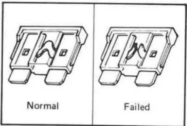
Fuses are located inside the left side cover. If a fuse fails during operation, inspect the electrical system to determine the cause, and then replace it with a new fuse of proper amperage.

A. Fuses
B. Spare Fuses
WARNING
Do not use any substitute for the standard fuse.
- Replace the blown fuse with a new one of the correct capacity, as specified on the fuse case.
Fuel System
Accumulation of moisture or sediment in the fuel system will restrict the flow of fuel and cause carburetor malfunction. The system should be checked in accordance with the Periodic Maintenance Chart.
WARNING
Gasoline is extremely flammable and can be explosive under certain conditions. Turn the ignition switch OFF. Do not smoke. Make sure the area is well ventilated and free from any source of flame or sparks; this includes any appliance with a pilot light.
Make sure the engine is cold before working. Wipe any fuel off the engine before starting it.
Inspection
●Turn the fuel tap to the PRI position.
- Connect a suitable hose to the fitting at the bottom of each carburetor float bowl.

A. Drain Screw
B. Suitable Hose
●Run the lower ends of the hoses into a suitable container.
●Turn out each drain screw a few turns to drain the carburetors, and check to see if water or dirt has accumulated in the carburetors.
●Tighten the drain screws.
NOTE
○If any water or dirt appeared during the above operation, have the fuel system checked by an authorized Kawasaki Dealer.
Cleaning
For the prolonged life of your motorcycle, wash it down immediately after it has been splashed with seawater or exposed to the sea breeze; operated on rainy days, rough roads, or in dusty areas; or operated on roads on which salt has been scattered for ice removal.
Preparation for Washing
Before washing, precautions must be taken to keep water off the following places:
●Rear openings of each muffler; Cover with plastic bags secured with rubber bands.
- Clutch and brake levers, switch housings on the handlebar; Cover with plastic bags.
- Ignition switch; Cover the keyhole with tape.
●Air cleaner intake; Close up the intake with tape, or stuff with rags.
Where to be Careful
Avoid spraying water with any great force near the following places:
●Speedometer and tachometer
●Disc brake master cylinder and caliper
●Rear hub; If water gets inside the hub, the rear brake will not function until it dries out.
●Under the fuel tank; If water gets into the ignition coils or into the spark plug caps, the spark will jump through the water and be grounded out. When this happens, the motorcycle will not start and the affected parts must be wiped dry.
●Front wheel hub
●Steering pivot (steering stem head pipe)
●Swing arm pivot
NOTE
○Coin operated, high pressure spray washers are not recommended. The water may be forced into bearings and
other components causing eventual failure from rust and corrosion. Some of the soaps which are highly alkaline leave a residue or cause spotting.
After Washing
- Remove the plastic bags and tape, and clean the air cleaner intake.
●Lubricate the pivots, bolts, and nuts.
●Test the brakes before motorcycle operation. - Start the engine and run it for 5 minutes.
WARNING
Never wax or lubricate the brake disc. Loss of braking and an accident could result. Clean the disc with an oilless solvent such as trichloroethylene or acetone. Observe the solvent manufacturer's warnings.
STORAGE
Preparation for Storage:
●Clean the entire vehicle thoroughly.
●Run the engine for about five minutes to warm the oil, shut it off and drain the engine oil.
●Put in fresh engine oil.
●Empty the fuel from the fuel tank, and empty the carburetors by unscrewing the drain screw at each float bowl. (If left in for a long time, the fuel will break down and could clog the carburetors.)
- Remove the empty fuel tank, pour about 250 mL (½ pint) of motor oil into the tank, roll the tank around to coat the inner surfaces thoroughly, and pour out the excess oil.
WARNING
Gasoline is extremely flammable and can be explosive under certain conditions. Turn the ignition switch OFF. Do not smoke. Make sure the area is well ventilated and free from any source of flame or sparks; this includes any appliance with a pilot light.
- Remove the spark plugs and put several drops of SE class SAE 30 oil into each cylinder. Push the starter button for a few seconds to coat the cylinder walls with oil, and install the spark plugs.
-
Reduce tire pressure by about 20%.
-
Set the motorcycle on a box or stand so that both wheels are raised off the ground. (If this cannot be done, put boards under the front and rear wheels to keep dampness away from the tire rubber.)
●Spray oil on all unpainted metal surfaces to prevent rusting. Avoid getting oil on rubber parts or in the brakes.
●Lubricate all the cables. - Remove the battery, and store it where it will not be exposed to direct sunlight, moisture, or freezing temperatures. During storage it should be given a slow charge (one ampere or less) about once a month. Keep the battery well charged during cold weather so that the electrolyte does not freeze and crack open the battery. The more discharged the battery becomes, the more easily it freezes.
●Tie plastic bags over the exhaust pipes to prevent moisture from entering.
●Put a cover over the motorcycle to keep dust and dirt from collecting on it.
Preparation after Storage:
- Remove plastic bags from exhaust pipes.
- Check the electrolyte level in the battery, charge the battery if necessary, and install it in the motorcycle. Be careful that the battery vent hose is not pinched and that it is kept away from the driving system and other frame parts.
●Make sure the spark plugs are tight.
●Fill the fuel tank with fuel.
- Check all the points listed in the Daily Safety Checks section.
●Lubricate the pivots, bolts, and nuts.
∴ SΔACD = SΔCOD + SΔCOD - SΔCOD + SΔCOD
VN750-A9
KAWASAKI
HEAVY INDUSTRIES, LTD.
CONSUMER PRODUCTS & COMPONENTS GROUP
Part No. 99922-1680-01
Printed in Japan
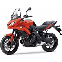
- VN750
- AUSTRALIAN MODEL ONLY
- TAMPERING WITH NOISE CONTROL SYSTEM
- OWNERS ARE WARNED THAT THE LAW MAY PROHIBIT
- WARNING
- CAUTION
- NOTE
- NOTICE
- FOREWORD
- KAWASAKI HEAVY INDUSTRIES, LTD. CONSUMER PRODUCTS & COMPONENTS GROUP
- TABLE OF CONTENTS
- SPECIFICATIONS
- PERFORMANCE
- DIMENSIONS
- ENGINE
- TRANSMISSION
- FRAME
- ELECTRICAL EQUIPMENT
- LOCATION OF PARTS
- GENERAL INFORMATION
- METER INSTRUMENTS
- SPEEDOMETER AND TACHOMETER
- COOLANT TEMPERATURE GAUGE
- FUEL GAUGE
- INDICATOR LIGHTS
- KEY
- IGNITION SWITCH/STEERING LOCK
- TO OPERATE THE IGNITION SWITCH
- RIGHT HANDLEBAR SWITCHES
- ENGINE STOP SWITCH
- STARTER BUTTON
- LEFT HANDLEBAR SWITCHES
- DIMMER SWITCH
- TURN SIGNAL SWITCH
- HORN BUTTON
- PASSING BUTTON
- FUEL TANK CAP
- FUEL TANK
- FUEL REQUIREMENTS
- OCTANE RATING
- FUEL TAP
- STANDS
- DOCUMENT/TOOL KIT CONTAINER
- SEAT
- HELMET HOOKS
- ELECTRIC ACCESSORY LEADS
- BREAK-IN
- HOW TO RIDE THE MOTORCYCLE
- STARTING THE ENGINE
- JUMP STARTING
- CONNECTING JUMPER CABLES
- MOVING OFF
- SHIFTING GEARS
- BRAKING
- STOPPING THE ENGINE
- STOPPING THE MOTORCYCLE IN AN EMERGENCY
- PARKING
- SAFE OPERATION
- DAILY SAFETY CHECKS
- ADDITIONAL CONSIDERATIONS FOR HIGH SPEED OPERATION
- MAINTENANCE AND ADJUSTMENT
- PERIODIC MAINTENANCE CHART
- ENGINE OIL
- OIL LEVEL INSPECTION
- COOLING SYSTEM
- RADIATOR AND COOLING FAN
- RADIATOR HOSES
- COOLANT
- COOLANT LEVEL INSPECTION
- COOLANT CHANGE
- TIGHTEN TORQUE
- FINAL GEAR CASE OIL
- SPARK PLUGS
- MAINTENANCE
- AIR CLEANER
- ELEMENT REMOVAL
- ELEMENT CLEANING
- THROTTLE GRIP
- INSPECTION
- ADJUSTMENT
- CHOKE LEVER
- CARBURETORS
- CLUTCH
- BRAKES
- BRAKE WEAR INSPECTION
- LUBRICATION
- DISC BRAKE FLUID
- FLUID REQUIREMENT
- RECOMMENDED DISC BRAKE FLUID
- FLUID LEVEL INSPECTION
- FLUID CHANGE
- FRONT BRAKE
- REAR BRAKE
- PEDAL POSITION INSPECTION
- PEDAL POSITION ADJUSTMENT
- PEDAL PLAY INSPECTION
- PEDAL PLAY ADJUSTMENT
- BRAKE LIGHT SWITCHES
- REAR SHOCK ABSORBERS
- AIR PRESSURE
- TO ADJUST THE AIR PRESSURE
- DAMPING FORCE
- WHEELS
- TIRES
- TIRE WEAR, DAMAGE
- TIRE DEPTH GAUGE
- BATTERY
- BATTERY INSTALLATION
- HEADLIGHT BEAM
- HORIZONTAL ADJUSTMENT
- VERTICAL ADJUSTMENT
- FUSES
- FUEL SYSTEM
- CLEANING
- PREPARATION FOR WASHING
- WHERE TO BE CAREFUL
- AFTER WASHING
- STORAGE
- PREPARATION FOR STORAGE
- PREPARATION AFTER STORAGE
- VN750-A9
- KAWASAKI
Marque : KAWASAKI
Modèle : VN 750
Catégorie : Moto