
FM-402 - Amplificateur audio Fusion - Notice d'utilisation et mode d'emploi gratuit
Retrouvez gratuitement la notice de l'appareil FM-402 Fusion au format PDF.


| Marque | Fusion |
| Modèle | FM-402 |
| Type de produit | Appareil électronique non catégorisé |
| Dimensions (L × l × H) | 120 × 80 × 30 mm |
| Poids | 200 g |
| Alimentation | Adaptateur secteur 5V / 2A (non inclus) ou 4 piles AA |
| Consommation électrique | 10 W max |
| Température de fonctionnement | 0 °C à 40 °C |
| Fonctions principales | Lecture audio, connectivité Bluetooth, port USB, écran LCD |
| Connectivité | Bluetooth 5.0, USB-A, prise jack 3,5 mm |
| Support de stockage | Carte microSD jusqu'à 32 Go |
| Autonomie (sur piles) | Environ 6 heures |
| Matériau du boîtier | Plastique ABS |
| Couleur | Noir |
| Entretien et nettoyage | Essuyer avec un chiffon doux et sec. Ne pas utiliser de produits abrasifs. |
| Sécurité | Ne pas exposer à l'humidité ou à des températures extrêmes. Débrancher en cas d'orage. |
| Pièces détachées et réparabilité | Piles, adaptateur secteur et câble USB disponibles séparément. Réparation par un professionnel recommandée. |
| Contenu de l'emballage | 1 × FM-402, 1 × câble USB, 1 × manuel d'utilisation |
| Garantie | 2 ans |
| Certifications | CE, RoHS |
FOIRE AUX QUESTIONS - FM-402 Fusion
Questions des utilisateurs sur FM-402 Fusion
0 question sur cet appareil. Repondez a celles que vous connaissez ou posez la votre.
Poser une nouvelle question sur cet appareil
Téléchargez la notice de votre Amplificateur audio au format PDF gratuitement ! Retrouvez votre notice FM-402 - Fusion et reprennez votre appareil électronique en main. Sur cette page sont publiés tous les documents nécessaires à l'utilisation de votre appareil FM-402 de la marque Fusion.
MODE D'EMPLOI FM-402 Fusion
FUSON®
User / Installation Manual
Marine Amplifier
FM-402

Contents
Feature Overview.....Pg 3
Control Descriptions ...... Pg 4
Installation....Pg 6
Connections....Pg 6
Inputs and Gain Setup ...... Pg 7
2 Channel Installation / Trouble Shooting ...... Pg 8
3 Channel Installation / Power Cable Calculator....Pg 9
4 Channel Installation / Specifications.....Pg 10
RECORD YOUR PRODUCT DETAILS HERE:
MODEL NUMBER DATE OF PURCHASE
AFFIX RECEIPT HERE
Feature Overview
• 2 Ohm Stable MOSFET Amplifier Design
• Variable Bass Boost 0 - +12dB
• Variable LP and HP Electronics X-OVER @ 12dB/octave
• FUSION Regulated Amplifier Technology (F.R.A.T.)
• FUSION Intercooled Semi-conductor Technology (F.I.S.T.)
• Gold Plated 4 Gauge Power and Ground Connections
• Gols Plated Audio Input and Output Connections
• FUTRANZ Efficient Heat Sink Transfer Technology
• Gold Plated RCA Output for multi-amp Installations
What sets FUSION apart?
The FUSION FM series amplifiers come complete with FRAT power supplies, FIST cooling system and FUTRANZ. Also all marine amplifiers use heat-tempered PCBs for maximum product life and performance. Gold plated connectivity, ensures your signal flows from the head unit through to the speakers with as little injected distortion and noise as possible. This results is a very clean and very powerful reproduction of the input signal. All these features make it easier to achieve sonic perfection in almost any installation.
FUTRANZ
In developing extremely powerful amplifiers, it is essential to keep things cool so FUSION developed a heat sink that has a heat dissipation ability like never before. This was not an easy task but none the less it was achieved, another important factor is efficiently transferring the heat from the semi-conductors to the heatsink, conventional designs use a white paste as the interface between these devices and the heatsink, this is not a perfect solution when complete surface coupling is required. So all Marine Ampliers come equipped with a composite heat transferring tape. Core heat in semi-conductors causes distortion and poor component performance characteristics. Testing has shown a massive reduction in core heat has been achieved by using the FUTRANZ heat transferring technology. In simplified terms this means excellent thermal stability and maximum component reliability.
F.I.S.T (fusion intercooled semi-conductor technology)
FIST is an innovative method of clamping down all internal power switching and audio output devices with an aluminium extrusion that has extremely low temperature co-efficiency. By using FLST it creates the perfect cooling solution, rapidly removing core heat from all associated semi-conductors from both sides of the device at once resulting in extremely low distortion an excellent thermal stability
F.R.A.T (fusion intercooled semi-conductor technology)
FRAT is a regulated amplifier design, FUSION regulated amplifiers allow an enormous amount of output power at the lowest voltage (12.6 Volts) and extreme output at 14.4 volts.
2010 Version 1.0
Control Descriptions

1 Bass Remote Selector
Use this switch to activate or deactivate the (optional) FP-BASS controller.
2 Bass Remote Connector
This port allows connections to the (optional) FP-BASS control.
3 Power And Status LEDs:
this shows if the amplifier has been correctly powered up and if any faults are present.
4 Crossover Selector:
Set the appropriate mode of operation. The 3 positions available are OFF, LP and HP. See points 5 and 6 below.
5 Low Pass:
Set the crossover switch 2 to LP when a subwoofer is connected. Ensure the crossover frequency is set at 100Hz or below, this feature is designed to filter all mid to high frequencies that only FULL RANGE speakers should produce. NOTE: Failure to do so could result in speaker damage.
6 High Pass:
Set the crossover switch 2 to HP and turn this control to 65Hz or above when using speakers smaller than 6 x 6", this feature is designed to filter all low bass frequencies that only SUBWOOFERS should produce. NOTE: Failure to do so could result in speaker damage.
7 Bass Boost:
This is a variable control to increase the bass boost at 45Hz from 0 -+18dB of gain, adjust to suit.
8 Subsonic Filter:
This is a variable control filters out all Sub Bass Frequencies below the set point at 18dB/octave.
9 Level:
This allows level adjustment of the input signal. Use this control to correctly match the head unit to the amplifier. To set this control correctly, turn the amplifier level to MIN and the head unit to 3/4 volume, with the BASS and TREBLE on zero, then slowly turn up this amplifier level control towards the MAX end of the control. NOTE: If the sound becomes distorted, turn this control down.
10 RCA Input:
Connect these RCA connectors to the rear LOW LEVEL output connection from the head unit.
11 RCA Output:
Use these RCA Output connectors to connect to a secondary amplifier. This output is a PASS-THRU connection derived from the RCA input connector so the signal level and frequency response are the same as the original input signal.
12 Ground Connection:
Connect directly to a suitable ground point via a 4 gauge power cable. NOTE: This is to be the first wire to connect when wiring up amplifiers. Damage could result of this is not done.
13 +12V Connection:
This must be connected to the battery positive (+) terminal via a 4 guage power cable and with an inline fuse or circuit breaker at the battery end. NOTE: This is to be the last wire to connect up during installation as damage could result.
14 Remote Connection:
This input is for turning the amplifier on and off. This requires a switched positive (+12V) to power 'ON' the amplifier, this can be found on the rear of the head unit in the form of an electric antenna output, or a remote on output. If not available you can wire to the ACC position on the key.
15 Fuses:
Please ensure the correct type of fuse is fitted, as specified in this manual. PLEASE NOTE: the FM-402 has 1x 25A fuses.
16 Speaker Output:
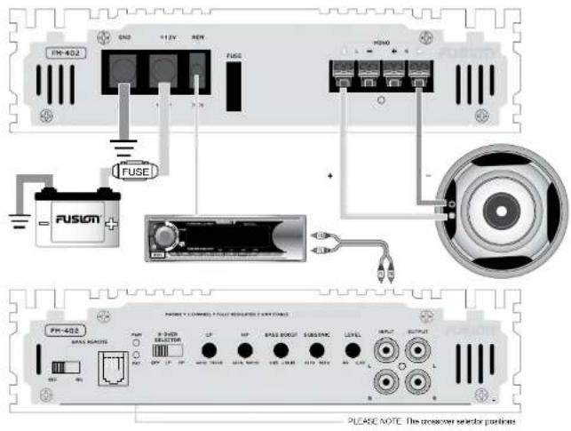
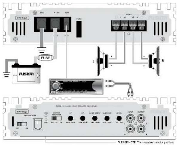
See 2/1 channel installation diagrams in this manual for correct speaker connection.
Installation
Mounting
Appropriate mounting is very important for the prolonged life expectancy of any amplifier. Select a location that allows enough space so sufficient airflow is maintainable and a location that provides protection from moisture. Keep in mind that an amplifier should never be mounted upside down. Upside down mounting will compromise heat dissipation through the heatsink and could engage the thermal protection circuit. Excessive heat will shorten your amplifiers life. To maximise heat dissipation, be sure to leave at least 2.5" of clearance around the amplifier. If space is of the essence and the amplifier must be mounted in an enclosed or restricted area, a small 3 inch fan should be used in correspondence with a duct so the heat can flow past the FUTRANZ Heatsink. Try to avoid mounting any amplifier on a subwoofer enclosure, as extended exposure to vibration may cause malfunction of the amplifier.
To avoid scratching your new FUSION amplifier, pre-drill the mounting holes with either a 3mm or 9/64" diameter drill bit and use the screws supplied in the accessory kit. Be sure to investigate your mounting area thoroughly to avoid electrical wires, vacuum lines and brake or fuel lines.
Installation Options
The quality of installation will affect the performance and reliability of your FUSION amplifier. For maximum performance we recommend you have your new FUSION amplifier installed by an authorised FUSION dealer. Our highly skilled dealers have vast knowledge of our products and their installation techniques are necessary to unleash the high performance capabilities of your amplifier.
If you decide to connect the amplifier yourself, it is important that you read this manual carefully and throughout before starting. Once you have finished reading and you still have questions regarding installation, we recommend your FUSION dealer.
Connection
FUSION amplifiers are designed to work within a 10 to 16 volt DC range. Before any wires are connected, the vessel's electrical system should be checked for correct voltage supply with the help of a voltmeter. First, check the voltage at the battery with the ignition in the OFF position. The voltmeter should read between 12 and 13.8 Volts. If your vehicles' electrical system is not up to these specification, we recommend having it checked by an auto electrician before any further installation. Once the vessel is checked, make certain the correct cable size is used. We recommend using the following cables calculator diagram on page 8 to calculate the correct power cable for your application.
Power
FUSION amplifiers should be wired directly to the battery using the appropriate sized cable. Start at the vehicle battery and run the power cable through to the amplifier. FUSION recommends the use of grommets when passing the power cable through any metal wall to avoid sharp corners or sharp body parts that may easily cut through the insulation on the cable.
Avoid running the power cable over engine components and near heater cores. The use of an inline fuse or circuit breaker is a must, this will prevent the risk of a potential fire caused be a short in your power cable. Connect the fuse holder or circuit breaker as close to the battery positive terminal as possible. Use a fuse or circuit breaker of equal value as that found on the chassis of your FUSION amplifier. You may now connect the cable to the battery, but remember to leave the fuse out or circuit breaker off until all other cable connections are made.
Ground
When grounding your FUSION amplifier, locate a metal area close to the amplifier that is a good source of ground. Once again, investigate the area you wish to use for electrical vires, vacuum lines, and brake or fuel lines. Use either a wire brush or sand-paper to eliminate unwanted paint. This will supply a better contact for your ground. Use the same gauge cable for ground as you did for the power. Secure the ground cable to the appropriate ground point using a bolt, star washer and nut. Spread silicon
over the screw and bare metal to prevent rust. Now its time to connect the power and ground cables to the amplifier. Cut both cables to length. Crimp the yellow spade connectors supplied to the power and ground. Use a hex type screwdriver to loosen the +12V and the GND connections on the amplifier. Terminate the ground first, and then the +12V and please make sure that you terminate them into the correct terminals. Then tighten the screws down securely.
Speaker Load
Keep in mind FUSION "FH" series amplifiers are high power amplifiers and not high current amplifiers. In other words they require a minimum impedance of 2 ohms STEREO and 4 ohms bridged MONO to operate trouble free. Too low of an impedance could send your FUSION amplifier into protection mode and/or damage the amplifier.
Remote Turn-on
This terminal must be connected to a switched +12V source. Typically, remote turn-on leads are provided at the head unit which will turn on and off the amplifier in correspondence with the source. If the head unit does not have a remote turn-on lead, then a power antenna wire can be used. If neither of these leads are present on the head unit then a switched +12V supply must be used, like the ACC +12V.
Run a minimum of 18 gauge wire from the amplifier location to the source of the switched +12V lead. If possible, route this wire on the same side of the vehicle as your power cable. Connect the source remote output to the wire. Go back to the amplifier and cut the wire to length. Loosen the screw terminal marked REM on the amplifier using a hex type screwdriver. Slip the wire into the connector and tighten the screw securely.
Speaker Wiring
Choose the correct speaker wire for your application. Most application will require a minimum of 16 gauge. Route these using the same precautions as you did when you ran the power cables. Terminate these wires at the speaker end using insulated speaker terminals (not supplied) or by soldering the connection. Make sure the speaker connections are positive to positive and negative to negative. At the amplifier end, use a +2 Phillips screwdriver to loosen the speaker terminals on the amplifier. Connect the speaker wires and tighten the screws securely. Check to make sure you've maintained proper polarity and balance.
Inputs & Gain Setup
Low Level Inputs
Be extra careful with your RCA interconnects. Hiss, engine noise, and fan noise can easily be picked up through RCA cables if run Incorrectly. Avoid running your RCAs near large wire looms and electric fans if possible. Run your RCA cables on the opposite side of the power cable. Be sure to check for correct balance (Red is right and black or white is left)
Level Control
On the amplifier, is the LEVEL control, this control allows you to match the input level of the amplifier to the output level of your head unit. Matching the input can be accomplished in three simple steps:
- Turn the LEVEL control on the amplifier to minimum.
- Turn up the head unit and adjust to 2/3 maximum volume ensuring that the BASS and TREBLE are set to zero.
- Adjust the LEVEL control until the desired volume is achieved without audible distortion.
Remember, the gain control is not a volume control. Ignoring the three steps above may leave you with damaged speakers and/or a damaged amplifier.
1 Channel Installation 2 Channel Installation
Power Cable Calculator
| Total Amperage | 6 | 4ft | 4-7ft | 7 | 10ft | 10-13ft | 13-16ft | 16-19ft | 19-22ft | 22-28ft | |||
| 0-20 | 14 | 12 | 12 | 10 | 10 | 8 | 8 | ||||||
| 20-35 | 12 | 10 | 8 | 6 | 6 | 6 | 4 | ||||||
| 35-50 | 10 | 8 | 6 | 4 | 4 | 4 | 4 | ||||||
| 50-65 | 8 | 8 | 6 | 4 | 4 | 4 | 4 | 7 | |||||
| 65-85 | 6 | 6 | 4 | 4 | 2 | 2 | 2 | ||||||
| 85-105 | 6 | 6 | 4 | 2 | 2 | 2 | 2 | ||||||
| 105-125 | 4 | 4 | 4 | 2 | 0 | 0 | 0 | ||||||
| 125-150 | 2 | 2 | 2 | 0 | 0 | 0 | 0 |
Trouble Shooting
| Problem | Cause | Solution |
| Power LED not 'ON' | Fuse at battery blown or not installed | Replace with correct fuse. Typically twice the rating of the fuse that is on the amplifier |
| Improper connections | Check that the ground wire, power wire and the remote wires are connected to the correct terminal | |
| Status LED 'ON' | Fuse or amplifier blown | Replace with the correct AMP rated fuse |
| Amplifier too hot | Move the amplifier into a more ventilated area | |
| Speaker wires shorted | Check that there are no speaker wires shorted to any other wire and also check if any wire is shorted to the vehicle chassis | |
| Internal malfunction | Disconnect all wires except ground, power and remote. Then turn the amplifier 'ON', if the protection light is still 'ON' then return for service |
Specifications
Bandwidth 10Hz - 40kHz
Signal to Noise >95dB
Separation >60dB
Input Sensitivity 300mV - 8V
LP Variable Crossover 40Hz - 160Hz @ 12dB/octave
HP Variable Crossover 40Hz - 600Hz @ 12dB/octave
Variable Bass Boost 0 - +18dB @ 45Hz
Variable Subsonic Filter 20Hz - 55Hz @ 18dB/octave
Input Impedance 20KW
Damping factor >200
T.H.D 0.05%
Fuse Ratings 1 x 25A
Dimensions(mm) 220 (W) x 260(L) x 57.5(H)
12.6 Volt power output specification
50 Watts RMS x 2 @ 40.1% THD+N
96 Watts RMS x 2 @ 20.1% THD+N
160 Watts RMS x 1 @ 4Ω Bridged 1% THD+N
14.4 Volt power output specification
65 Watts RMS x 2 @ 40.1% THD+N
100 Watts RMS x 2 @ 20.1% THD+N
200 Watts RMS x 1 @ 4Ω Bridged 1% THD+N
Specifications and design are subject to change without notice.
- FUSON®
- MARINE AMPLIFIER
- CONTENTS
- RECORD YOUR PRODUCT DETAILS HERE
- FEATURE OVERVIEW
- WHAT SETS FUSION APART
- FUTRANZ
- F.I.S.T (FUSION INTERCOOLED SEMI-CONDUCTOR TECHNOLOGY)
- F.R.A.T (FUSION INTERCOOLED SEMI-CONDUCTOR TECHNOLOGY)
- CONTROL DESCRIPTIONS
- 1 BASS REMOTE SELECTOR
- 2 BASS REMOTE CONNECTOR
- 3 POWER AND STATUS LEDS
- 4 CROSSOVER SELECTOR
- 5 LOW PASS
- 6 HIGH PASS
- 7 BASS BOOST
- 8 SUBSONIC FILTER
- 9 LEVEL
- 10 RCA INPUT
- 11 RCA OUTPUT
- 12 GROUND CONNECTION
- 13 +12V CONNECTION
- 14 REMOTE CONNECTION
- 15 FUSES
- 16 SPEAKER OUTPUT
- INSTALLATION
- MOUNTING
- INSTALLATION OPTIONS
- CONNECTION
- POWER
- GROUND
- SPEAKER LOAD
- REMOTE TURN-ON
- SPEAKER WIRING
- INPUTS & GAIN SETUP
- LOW LEVEL INPUTS
- LEVEL CONTROL
- SPECIFICATIONS
Marque : Fusion
Modèle : FM-402
Catégorie : Amplificateur audio