
FGWPE-101 - Maison intelligente Fibaro - Notice d'utilisation et mode d'emploi gratuit
Retrouvez gratuitement la notice de l'appareil FGWPE-101 Fibaro au format PDF.


| Type de produit | Module Z-Wave pour volet roulant |
| Dimensions | 41,5 x 36,5 x 17 mm |
| Poids | 23 g |
| Alimentation | 230 V AC, 50 Hz |
| Consommation électrique | Max 0,2 W |
| Fonctions principales | Contrôle de volets roulants, stores et stores vénitiens ; commande via Z-Wave ; mesure de consommation |
| Protection | Protection contre les surcharges et les courts-circuits |
| Entretien et nettoyage | Essuyer avec un chiffon sec ; ne pas utiliser de produits abrasifs |
| Sécurité | Installation par un professionnel qualifié ; respecter les normes électriques locales |
| Pièces détachées et réparabilité | Aucune pièce réparable par l'utilisateur ; contacter le service client Fibaro |
| Informations générales | Compatible avec les passerelles Z-Wave ; température de fonctionnement : 0-40°C ; classe IP20 |
FOIRE AUX QUESTIONS - FGWPE-101 Fibaro
Questions des utilisateurs sur FGWPE-101 Fibaro
0 question sur cet appareil. Repondez a celles que vous connaissez ou posez la votre.
Poser une nouvelle question sur cet appareil
Téléchargez la notice de votre Maison intelligente au format PDF gratuitement ! Retrouvez votre notice FGWPE-101 - Fibaro et reprennez votre appareil électronique en main. Sur cette page sont publiés tous les documents nécessaires à l'utilisation de votre appareil FGWPE-101 de la marque Fibaro.
MODE D'EMPLOI FGWPE-101 Fibaro
Operating Manual
Fibaro Wall Plug
FGWPE/F-101 v.2.1 - v.2.3
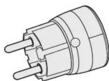
Fibaro Wall Plug is a universal, Z-Wave compatible, relay switch in the form of a socket adapter. The Plug may be used to operate any device up to 2,500W power output. The Plug features power consumption measuring and uses a crystal LED ring to visualize the current load by colour changing illumination.
Fibaro Wall Plug may be operated using the service button located on its casing, or via any Z-Wave compatible controller.
Specifications
| Power supply: | 110-230 V AC +10%, 50/60 Hz |
| Rated load current: | 11A, 110-230V, 50/60 Hz - continuous load13A, 110-230V, 50/60 Hz - momentary load |
| Power consumption: | up to 0.8W |
| Power output:(For resistive load) | 2.5kW at continuous load3.0kW at momentary load |
| In accordance with EU standards: | EN 55015 (noise)EN 60669-2 (-) (operational safety) |
| Circuit's temperature limit: | 105 °C |
| Operational temperature: | 0 - 40 °C |
| Circuit's thermal protection: | 115 °C - Ta (Ta = ambient temperature) |
| To be used with E or F type (Schuko) sockets: | - CEE 7/16 - max load 2,5 A- CEE 7/17 - max load 18A - Dual type plugs E/F |
Radio signal power:
Radio protocol:
Radio frequency
Range:
Dimensions: (D x H):
1mW
Z-Wave
868,4 MHz
up to 50m outdoors
up to 30m indoors (depending on building materials)
。
45 x 65mm

NOTE
In case of loads other than resistive please observe cosφ and use load lower than rated if necessary. It's recommended not to exceed 8A / 1,5kW
Technical Information
Controlled by Fibaro devices or any other Z-Wave controller
Microprocessor control Executive element - rela
Active and historic (average) power consumption measuring
I. General information about Fibaro System
Fibaro is a wireless system, based on Z-Wave technology. Fibaro provides many advantages when compared to similar systems. In general, radio systems create a direct connection between the receiver and transmitter. But the radio signal is weakened by various obstacles located on its path (apartment walls, furniture, etc.) and in extreme cases it fails to transfer required data. The advantage of Fibaro System is that its devices, apart from being transmitters and receivers, are also signal duplicators. When a direct connection path between the transmitter and the receiver cannot be established, the connection may be achieved through other intermediate devices.
Fibaro is a bi-directional wireless system. This means that the signal is not only sent to the receivers, but also the receivers send the confirmation of its reception. This operation confirms their status to check whether they are active. Safety of the Fibaro System transmission is comparable to the safety of transmission in data bus wired systems.
Fibaro operates in the free band for data transmission. The frequency depends on radio regulations in individual country. Each Fibaro network has its own unique network identification number (home ID), which is why it is possible to co-operate two or more independent systems in a single building without any interference. Although Z-Wave is quite new technology, it has already become recognizable and officially binding standard, similarly to Wi-Fi. Many manufacturers in various industries offer solutions based on Z-Wave technology, guaranteeing their compatibility. This means that the system is open and it may be extended in the future. Find more information at www.fibaro.com.
Fibaro generates a dynamic network structure. After Fibaro System is switched on, the location of its individual components is automatically updated in real-time through status confirmation signals received from devices operating in a "mesh" network. The Fibaro Wall Plug is hereinafter referred to as Plug. It is designed to turn on / off electrical devices (see specifications) using radio waves, controllers and push button located in it's casing. Plug automatically recognizes connected load and is protected from overcurrent or short circuit. Features unique, real-time energy consumption measuring through color changing, crystal LED ring.
II. Installation
Theorem 1.2. (Theorem 1.3) Let be a finite field and let (x) be the set of all elements of . Then
1) Insert device into a socket, 2) Add device into the Z-Wave network if necessary.
3) Connect load to the Plug, making sure it does not exceed
2500W 4) Set the c
4) Set the connected device switch to ON. 5) To turn on connected device manually to
button. (Alternative to remote control via Z-Wave controller)
Once the Plug is turned on, LED ring will glow.
6) Current power load is visualized with LED hit 7) Press B button to turn off the Plug manually.
1) Press D button to turn on the Plug manually, 8) Once the Plug is turned off, LED ring illumination is turned off as
well.
III. Z-Wave network inclusion
Fibaro Wall Plug may be controlled manually, by the B button located on its casing, or via any Z-Wave controller. To include the Plug into the Z-Wave network please complete following tasks:
1) Insert the Plug into a socket,
2) Auto-inclusion will be activated, i.e. Plug automatically starts
looking for Z-Wave network controller. Auto-inclusion activation is signaled by a single, red LED ring blink.
3) Set the Z-Wave network main controller into learning mode (see
Z-Wave network controller operating manual)
4) Fibaro Wall Plug should be recognized and automatically included into the 7 Wave network.
After the inclusion process is completed, Plug's auto-inclusion
function is deactivated, i.e. Plug will not try to include itself into the
—
The Ground Truth image displays a single, continuous horizontal line, which is a stylistic or background element (like a ruled paper line). According to Rule 2, such lines must be ignored by the OCR result. The provided OCR content is "____", which consists of underscores. Underscores are not equivalent to a solid line and are not permitted under the “Stylistic/Background Lines (Ignore)” rule. Outputting underscores for a stylistic line is incorrect because it misinterprets the line as a fill-in-the-blank placeholder. Since the OCR output incorrectly rendered a stylistic line as underscores (which should be ignored), this violates the rule. Therefore, the OCR result is inconsistent with the Ground Truth.
The Ground Truth image displays a single, solid horizontal line, which is a stylistic or background element (like a rule line on paper). According to Rule 2, such lines must be ignored by the OCR result. The provided OCR content is "____", which consists of underscores. Underscores are not equivalent to a solid line and are not permitted under the “Stylistic/Background Lines (Ignore)” rule. Outputting underscores for a stylistic line is incorrect because it misinterprets the line as a placeholder fill-in-the-blank area. Since the OCR output incorrectly rendered a stylistic line as underscores (which should be ignored), this violates the rule. Therefore, the OCR result is inconsistent with the Ground Truth.
NOTE
To disable auto-inclusion press the B button once
after inserting the Plug into a socket
To include the Plug manually, without the use of auto-inclusion:
1) Set the Z-Wave controller into the learn-mode (see Z-Wave
controller operating manual),
2) Triple click the B button, located on the Plug's casing
IV. Removing from Z-Wave network
To remove Fibaro Wall Plug from the Z-Wave network:
The following table is provided in the image.
1) Insert the Plug into a socket, 2) Set the Z Wave network controller into the loop mode /sec
Z-Wave controller operating manual)
3) Triple click the B button, located on the Plug's casing.
V. Resetting Fibaro Wall Plug
Reset procedure clears the Plug's memory, including Z-Wave
network controller information and energy consumption data. To assist Fibers Wall Plugs
To reset Fibero Wall Plug.
1) Insert the Plug into a socket,
2) Press and hold the B button for 15 - 20 seconds until LED ring
glows yellow,
4) Press the B button, briefly
Once the reset procedure is completed, LED ring will glow red and turn off. Plug's relay will turn off as well.

NOTE
Resetting the Plug does not mean is has been removed from TWave network controllers.
removed from Z-Wave Network Controller's memory. Remove the Plug from Z-Wave network
controller's memory resetting procedure
VI. Operating the Plug through Z-Wave network
After successful inclusion Plug will be represented in the Home Center 2 by the following, single icon:
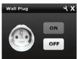
Fig. 1 Wall Plug icon in Home Center 2 interface
Clicking ON/OFF will turn a connected device On or Off.
VII. Association
Through an association Fibaro Wall Plug may control another Z-Wave network device, e.g. another Fibaro Wall Plug, Dimmer, Relay Switch or Roller Shutter.

Association allows for direct communication
between Z-wave network devices. Main controller does not take part in such communication.
does not take part in such communication
The Fibaro Wall Plug provides three association groups:
I association group is assigned to Plugs status - On / Off. Allows for sending control command to associated devices whenever the Plug is turned On or Off.
II association group allows for sending control commands to associated devices depending on the current load. This association group is configured through the advanced parameters no. 50, 51 and 52.
III association group reports relay's status to just one device, Z-Wave network's main controller by default. It's not recommended to modify settings of this association group.
The Fibaro Wall Plug allows for associating 5 normal devices per single association group, out of which 1 field is always reserved for main controller.

NOTE
Group I association commands are sent only in
Case of manual operation through the D button. Group II association commands are cont
automatically, depending on parameters no. 50, 51
and 52 settings.
To add an association (using Home Center 2 Interface) go to device
settings and click the following icon:
Select the "device options" tab. Then specify to which group and what devices are to be associated. Sending relevant information to devices added to association groups may take even a few minutes.
VIII. Current load and energy consumption
1) Fibaro Wall Plug allows for the current load and power consumption monitoring. Data is sent to the main controller, e.g. Home Center 2. Measuring is carried out by an independent microprocessor dedicated exclusively for this purpose, assuring maximum accuracy and precision.
Electric power - power consumed by an electric device in an instant, in Watts (W).
Electric energy - energy consumed by a device through a time period. Most commonly measured in kilowatt-hours (kWh). One kilowatt-hour is equal to one kilowatt of power consumed over a period of one hour, 1kWh = 1000 Wh.

NOTE
Please contact your local electricity supplier for the current rate.
current rates
2) Fibaro Wall Plug stores consumed electricity data in its memory, which means disconnecting the Plug from a socket does not erase the data.
To reset electricity consumption memory:
a) Insert the Plug in a socket, b) Brass and hold the B button for 5-10 seconds until LED ring
olows green,
c) Release the B button,
d) Press the B button briefly
Resetting electricity consumption memory will be signaled by double, green, LED ring blink. Plug's relay won't change its status.

NOTE
Some Z-wave network controllers allow for reselling electricity consumption from controllers
menu
3) Frequently asked questions about power and energy consumption measuring
Why doesn't a device consumes precisely 100% when its data
plate says this is the power exactly?
Power data specified by producers are often based on rough estimates or measured in perfect conditions. Real world power depends on mains voltage, device condition or ambient conditions the device is used in. It may happen that two identical devices will consume different amounts of energy.
Why power of the same device differs depending on the socket it is connected to, in the same house?
Such things happen because of mains voltage fluctuations. Causes
Why the power of the same device differs in times of day?
The reason is the mains voltage fluctuations.
Why do we measure power, not any other parameter instead?
Power measuring is important because based on this parameter electricity suppliers charge households for energy use.
Why certain devices power fluctuates instead of being
constant?
Some devices may have such a characteristic, e.g. computers. In case of devices frequently, significantly changing power consumption, e.g. plasma TVs, it is recommended to modify configuration parameters to optimize the Z-Wave network use. Modify parameters no. 40, 42 and 43 settings in order to reduce the frequency of reporting the power use.
To reduce the number of power reports, value of the parameters 42 and/or 43 must be increased, based on user's experience. (e.g. parameter 42 set to 30 and parameter 43 set to 60).
IX. Led rings settings and readings
The Fibaro Wall Plug has built-in, colour changing LED ring, signaling connected devices power and operating status. Colours shown are those of a RGB scheme. In addition, the LED ring signals Plugs range in relation to the Z-Wave networks main controller and overheating protection activation (parameter no.70).
LED rings signaling modes:
1) Wall Plugs On / Off signaled with a color defined by relevant
parameter settings (see parameters no. 60, 61, 62)
2) Alarm status signaled according to parameters 63 settings,
3) Energy meter reset signaled by double, green blink,
4) Once inserted to mains socket, LED ring signals Z-Wave network
blink means Plug has not been included in the Z-Wave network.
5) Blinking yellow means memory write during software update
prossoo;
6) Alternating blinking, yellow / red, signals overheating warning (overload)
LED ring illumination may be turned off completely. To do so:
1) Insert the Plug in a socket,
2) Press and hold the B button for 2-5 seconds, till LED ring starts
Fasting
3) Release the B button,
4) Press the B button briefly.
Plugs relay will not change its status. After the LED ring has been turned off, it can be turned on by completing again the above procedure.

NOTE Turnip
As well.
[Non-Text]
The Fibaro Wall Plug features built-in network range status, in relation to the Z-Wave network main controller.
To test the range:
1) Insert Plug into a mains socket,
2) Press and hold the B button for 10-15 seconds until the LED ring
3) Release the B button.
4) Press the B button briefly.
5) LED ring signals Z-Wave network range - see below for signaling
(1) 2016年1月1日
6) To exit range testing mode press the B button briefly. Plugs relay
Z-Wave network range signaling modes:
LED ring pulsing green - Wall Plug tries to establish direct connection with the main controller. If direct connection cannot be established, Plug will try routing connection with the main controller which will be signaled by LED ring pulsing yellow.
LED ring glowing green - Wall Plug managed to establish a direct
LED ring pulsing yellow - Wall Plug is trying to establish routed connection with the main cotroller, via other Z-Wave devices acting as signal repeaters.
LED ring glowing yellow - Wall Plug managed to establish routed connection with the main controller. After 2 seconds the Plug will try again to establish a direct connection with the main controller, which will be signaled by LED ring pulsing green.
LED ring pulsing violet - Wall Plug is located outside the Z-Wave network's range or the network is busy. Ultimately, failure to connect with the main controller will be signalled by LED ring pulsing red. After 2 seconds the Plug will again try to establish a direct connection with the main controller which will be signalled by LED ring blinking green.
X. Advanced configuration
Fibaro Wall Plug offers a wide variety of advanced configuration settings. Below parameters can be accessed from main controllers configuration interface.
To configure Wall Plug using Home Center 2 controller go to device
options by clicking the following ico
3
•
GENERAL:
- Always on function
Once activated, Wall Plug will keep a connected device constantly ON, will stop reacting to alarm frames and B-button push.
"Always on" function turns the Plug into a power and energy meter. Also, connected device will not be turned off upon receiving an alarm frame from another Z-Wave device (parameter 35 will be ignored).
In "Always on" mode, connected device may be turned off only after user defined power has been exceeded (parameter 70). In such a case, connected device can be turned on again by pushing the B-button or sending a control frame. By default, overload protection is inactive. Default setting: 1
Available settings:
0 - function activated
- 本报告书不存在虚假记载、误导性陈述或者重大遗漏。
( )
16 - Remember device status after power failure
Define how will the Plug react after the power supply is back on. Default setting: 1
Available settings:
0 - Wall Plug does not memorize its state after a power failure.
Connected device will be on after the power supply is reconnected.
1 - Wall Plug memorizes its state after a power failure.
Parameter: 1 [byte]
ALARMS:
Z-Wave network alarm will be signalled by LED ring according to the parameter 63 settings. Blinking in Red/Blue/White is a default setting.
Connected device state will be changed according to the parameter 35 settings. By default, connected device state will remain unchanged.
Wall Plug will be signaling an alarm through the time period specified in the parameter 39 (10 minutes by default), unless the alarm is cancelled earlier. In addition Wall Plug may exit the alarm mode after the B-button has been pressed and held for 2 - 5 seconds.
____
- Reaction to alarms. Define Z-Wave network alarms to which the Wall Plug will respond. Default setting: 63
Available settings: 0 - 63.
1 - general alarm 2 - smoke alarm
4 - CO alarm,
8 - CO2 alarm, 46 - high temperature alarm
32 - flood alarm
63 - device responds to all types of alarm frames.
Set value may be a sum of available values, e.g. set value = 5 means the Plug will respond to general alarm (1) and CO alarm (4).
Parameter: 1 [byte]
- Wall Plug's response to alarm frames
status change) Default setting: 0
Available settings:
0 - no reaction
1 - turn on connected device. LED ring signals an alarm through defined time period (parameters 30) or until the alarm is
cancelled.
2 - turn off connected device. LED ring signals an alarm through defined time period (parameters 70) so until the alarm is
cancelled
3 - cyclically change device state, each 1second. In alarm mode
Wan P flag does not report status change; power charges; ignores alarm frames. After the defined time period has passed
(parameter 39) or after the alarm cancellation, connected
advice to set to the private state
Parameter: 1[byte]

NOTE
If "always on" function is active (parameter 1), this
param
[Non-Text]
51
arm mode duration. If a device sending an alarm frame
Z-Wave network sets alarm duration as well, this
stung
g: 600 (seconds).
ings: 1 - 65536 (seconds)
[udol]
[Non-Text]
Power load, sent to the main controller. Default settings meters are chosen in such a way that instantaneous s shown without blocking the Z-Wave network in the fault settings are good for most of the devices. In it may be necessary to modify default settings in order of Wave network's use. In extreme cases it is recommend- f reporting completely and configure power polling or cts in Home Center 2.
Plug reports the power load with specified frequency, duration parameters allow to specify how and how lower load will be reported.
e power report
defines by how much power load must change, in be reported to the main controller, with the highest Z-Wave network. By default, Fibaro Wall Plug ends power report if the power load changes by 80%. ng: 80 (%)
ings: 1 - 100 (%).
(%) means the reports are turned off.
byte]
NOTE In extreme cases, reports may be sent every second if rapid and significant power load changes occur. Frequent reporting may overload the Z-Wave network so these parameter's settings should reflect significant changes in power load only.
∴ m = 3/11
- Standard power load reporting
Parameter defines by how much power load must change, in
percents, to be reported to the main controller. By default, Fibaro
Wall Plug sends power report if the power load changes by 15%. By default such changes in power load may be reported up to 5 times.
By default such changes in power load may be reported up to 5 times per 30 seconds. Wall Plug sends 5 reports during time period
per 50 seconds. Wall Flug senda 5 reports during time period specified in parameter 43.
Default setting: 15 (%)
Available settings: 1 - 100 (%)
Value of 100 (%) means the reports are turned off.
Parameter: 1[byte]
- Power reporting frequency
This parameter defines how frequently standard power reports
(parameter 42) will be sent. By default Wall Plug sends up to 5
reports each 30 seconds, provided the power load changes by 15% Default setting: 30 (s)
Available settings: 1 - 254 (s)
Value of 255 - Reports will be sent only as a result of parameter 47
settings or in case of polling.
Parameter: 1[byte]
- Reporting changes in energy consumed by controlled
devices
New, reported energy value is calculated based on last reported value. Default setting: 10 (0.1 kWh)
Value: Default setting. 10 (6,1 KWH).
Available settings. 1 * 234 (0,01kWh * 2,34kWh).
Value of 255 - changes in consumed energy will not be reported.
Reports will be sent only in case of polling.
Parameter: 1[byte]
- Time period between reports on power load and energy
consumption.
Parameter defines time period between reports sent when changes
in power load have not been recorded. By default, if power load changes have not been recorded, we do not even have
changes have not been recorded, reports are sent every hour. Default setting: 3 600 (s).
Available settings: 1 - 65534 (s)
Value of 65535 - no periodic reports. Reports will be sent only in
case of power load / energy consumption changes (parameters 40,
42, 43, 45) or in case of polling.
Parameter: Z[byte]
- Metering energy consumed by the Wall Plug itself.
This parameter determines whether energy metering should include
the amount of energy consumed by the Wall Plug itself.
Results are being added to energy consumed by controlled device.
Default setting: 0
Available settings:
0 - function inactive,
1 - function activated.
Parameter: 1[byte]
ASSOCIATION GROUP 2
Status of devices added to 2nd Association Group may depend on
Status of device based to the Association Group may depend on power consumed by the connected device. For example, turning on
the TV controlled by the Plug will turn off the lights in the room.
User defines two thresholds: UP and DOWN, and then defines the
reaction to them being exceeded (parameter 52).
- DOWN value
Lower power threshold, used in parameter 52
Default setting: 300 (30 W)
Available settings: 0 - 25 000 (0.0W - 2 500W)
DOWN value cannot be higher than a value specified in parameter
51.
Parameter: 2[byte]
- UP value
Upper power threshold, used in parameter 52
Default setting: 500 (50 W)
Available settings: 1 - 25 000 (0,1W - 2 500W)
UP value cannot be lower than a value specified in parameter 50
Parameter: 2[byte]
- Action in case of exceeding defined power values (parameters 50 and 51)
Parameter deifies the way 2nd association group devices are controlled, depending on the current power load.
Default setting:
0 - function inactive
1 - turn the associated devices on, once the power drops below DOWN value (parameter 50),
2 - turn the associated devices off, once the power drops below DOWN value (parameter 50),
3 - turn the associated devices on, once the power rises above UP value (parameter 51).
4 - turn the associated devices off, once the power rises above UP value (parameter 51).
5 - 1 and 4 combined. Turn the associated devices on, once the power drops below DOWN value (parameter 50). Turn the associated devices off, once the power rises above UP value (parameter 51).
6 - 2 and 3 combined. Turn the associated devices off, once the power drops below DOWN value (parameter 50). Turn the associated devices on, once the power rises above UP value (parameter 51).
Parameter: 1[byte]
COLOUR SETTINGS
- Power load, which when exceeded, makes the LED ring flash violet
Function is active only when parameter 61 is set to 0 or 1 Default setting: 25 000 (2 500W)
Available settings: 1 000 - 32 000 (100W - 3200W).
Parameter: 2[byte]
- LED ring illumination colour when controlled device is on. Default value: 1
Available settings
0 - LED ring illumination colour changes in predefined steps, depending on power consumption changes,
1 - LED ring illumination colour changes continuously, using full spectrum of available colorus, depending on power consumption changes.
2 - White illumination
3 - Red illumination.
4 - Green illumination,
5 - Blue illumination,
6 - Yellow illumination,
7 - Cyan (Greenish blue) illumination.
8 - Magenta (Purnlish red) illumination
9 - illumination turned off completely
Parameter: 1[byte]
- LED ring illumination color when controlled device is off. Default setting: 8
0 - LED ring is illuminated with a color corresponding to the last measured power, before the controlled device was turned off
1 - White illumination
- Rod illumination
3 - Green illumination.
4 - Blue illumination
- Yellow illumination
6 - Cyan (Greenish blue) illumination.
- Magenta (Durelich red) illumination
8 - illumination turned off completely
Parameter: 1[byte]
- LED ring illumination colour at the Z-Wave network alarm detection. Default setting: 1
Available settings
0 - No change in colour. LED ring illumination colour determined by parameters 61 or 62 settings,
1 - LED ring flashes red / blue / white (default)
2 - White illumination
3 - Red illumination
-
Cross illumination
-
Blue illumination
-
Yellow illumination
-
Curr (Greenish blue) illumination
8 - Magenta (Purplish red) illumination
- Illumination turned off completely
Parameter: 1(byte)
SAFETY
- Oveload safety switch
This function allows for turning off the controlled device in case of exceeding the defined power. Controlled device will be turned off even if "always on" function is active (parameter 1).
Controlled device can be turned back on via B-button or sending a control frame. By default this function is inactive.
Default setting: 65 535 (6 553,5W)
Available settings: 10 - 65 535 (1W - 6 553.5W)
Value higher than 32 000 (3 200W) turns the overload safety switch off, i.e. this functionality is turned off by default.
Parameter: 2[byte]

NOTE This functionality is not an overload safety protection nor a short circuit protection. Circuit needs additional short circuit and overload protection.
XI. Guarantee
-
The Guarantee is provided by FIBAR GROUP Sp. z o.o. (hereinafter "Manufacturer"), based in Poznan, ul. Lotnicza 1; 60-421 Poznan, entered in the register of the National Court Register kept by the District Court in Poznań, VIII Economic Department of 1 National Court Register, no. 370151, NIP 7811858097, REGON: 301595664.
-
The Manufacturer is responsible for equipment malfunction resulting from physical defects (manufacturing or material) of the Device for 12 months from the date of its purchasing.
-
During the Guarantee period, the Manufacturer shall remove any defects, free of charge, by repairing or replacing (at the sole discretion of the Manufacturer) any defective components of the Device with new or regenerated components, that are free of defects. When the repair impossible, the Manufacturer reserves the right to replace the device with a new or regenerated one, which shall be free of any defects and its condition shall not be worse than the original device owned by the Customer.
-
In special cases, when the device cannot be replaced with the device of the same type (e.g. the device is no longer available in the commercial offer), the Manufacturer may replace it with a different device having technical parameters similar to the faulty one. Such activity shall be considered as fulfilling the obligations of the Manufacturer. The Manufacturer shall not refund money paid for the device.
-
The holder of a valid guarantee shall submit a guarantee claim through the guarantee service. Remember: before you submit a guarantee claim, contact our technical support using telephone or e-mail. More than 50% of operational problems is resolved remotely, saving time and money spent to initiating guarantee procedure. If remote support is insufficient, the Customer shall fill the guarantee claim form (using our website - www.fibargroup.com) in order to obtain claim authorization.
When the guarantee claim form is submitted correctly, the Customer shall receive the claim confirmation with an unique number (Return Merchandise Authorization -RMA).
-
The claim may be also submitted by telephone. In this case, the call is recorded and the Customer shall be informed about it by a consultant before submitting the claim. Immediately after submitting the claim, the consultant shall provide the Customer with the claim number (RMA-number).
-
When the guarantee claim form is submitted correctly, a representative of the Authorised Guarantee Service (hereinafter as "AGS") shall contact the Customer.
-
Defects revealed within the guarantee period shall be removed not later than 30 days from the date of delivering the Device to AGS. The guarantee period shall be extended by the time in which the Device was kept by AGS.
-
The faulty device shall be provided by the Customer with complete standard equipment and documents proving its purchase.
-
Parts replaced under the guarantee are the property of the Manufacturer. The guarantee for all parts replaced in the guarantee process shall be equal to the guarantee period of the original device. The guarantee period of the replaced part shall not be extended.
-
Costs of delivering the faulty device shall be borne by the Customer. For unjustified service calls, the Service may charge the Customer with travel expenses and handling costs related to the case.
-
AGS shall not accept a complaint claim only when: • the Device was misused or the manual was not observed,
the Device was provided by the Customer incomplete, which accessories or nameplate,
- It was determined that the result was caused by other reasons than a material or manufacturing defect of the Device
- the guarantee document is not valid or there is no proof of purchase,
-
The Manufacturer shall not be liable for damages to property caused by defective device. The Manufacturer shall not be liable for indirect, incidental, special, consequential or punitive damages, or for any damages, including, inter alia, loss of profits, savings, data, loss of benefits, claims by third parties and any property damage or personal injuries arising from or related to the use of the Device.
-
The guarantee shall not cover; • mechanical damages (cracks, fractures, cuts, abrasions, physical deformations caused by impact, falling or dropping the device or other object, improper use or not observing the operating manual);
- damages resulting from external causes, e.g.: flood, storm, fire lightning, natural disasters, earthquakes, war, civil disturbance, force majeure, unforeseen accidents, theft, water damage, liquid leakage, battery spill, weather conditions, sunlight, sand, moisture, high or low temperature, air pollution;
- damages caused by malfunctioning software, attack of a computer virus, or by failure to update the software as recommended by the Manufacturer;
- damages resulting from: surges in the power and/or telecommunication network, improper connection to the grid in a manner inconsistent with the operating manual, or from connecting other devices not recommended by the Manufacturer.
- damages caused by operating or storing the device in extremely adverse conditions, i.e. high humidity, dust, too low (freezing) or too high ambient temperature. Detailed permissible conditions for operating the Device are defined in the operating manual; - damages caused by using accessories not recommended by the Manufacturer
- damages caused by faulty electrical installation of the Customer, including the use of incorrect fuses:
- damages caused by Customer's failure to provide maintenance and servicing activities defined in the operating manual:
- damages resulting from the use of spurious spare parts or accessories improper for given model, repairing and introducing alterations by unauthorized persons;
Schools designed by operating room, 2010 or 2015
-
The scope of the guarantee repairs shall not include periodic maintenance and inspections, in particular cleaning, adjustments, operational checks, correction of errors or parameter programming and other activities that should be performed by the user (Buyer). The guarantee shall not cover natural wear and tear of the Device and its components listed in the operating manual and in technical documentation as such elements have a defined operational life.
-
If a defect is not covered by the guarantee, the Manufacturer reserves the right to remove such defect at its sole discretion, repairing the damaged or destroyed parts or providing components necessary for repair or replacement.
-
This guarantee shall not exclude, limit or suspend the Customer rights when the provided product is inconsistent with the purchase agreement.

This Device may be used with all devices certified with Z-Wave certificate and should be compatible with such devices produced by other manufacturers. Any device compatible with Z-Wave may be added
Any device compatible with Z-Wave may be added to Fibaro system.
FIBARGROUP
FIBARO
In case of any technical questions contact customer service centre in your country.
www.fibargroup.com


- TECHNICAL INFORMATION
- GENERAL INFORMATION ABOUT FIBARO SYSTEM
- INSTALLATION
- Z-WAVE NETWORK INCLUSION
- REMOVING FROM Z-WAVE NETWORK
- RESETTING FIBARO WALL PLUG
- OPERATING THE PLUG THROUGH Z-WAVE NETWORK
- ASSOCIATION
- CURRENT LOAD AND ENERGY CONSUMPTION
- LED RINGS SETTINGS AND READINGS
- ADVANCED CONFIGURATION
- GENERAL
- ALARMS
- GUARANTEE
Marque : Fibaro
Modèle : FGWPE-101
Catégorie : Maison intelligente