
PI30 - Navigateur SIMRAD - Notice d'utilisation et mode d'emploi gratuit
Retrouvez gratuitement la notice de l'appareil PI30 SIMRAD au format PDF.


| Type de produit | Navigateur GPS marin |
| Marque | Simrad |
| Modèle | PI30 |
| Dimensions (L x H x P) | 265 x 170 x 75 mm |
| Poids | 1,8 kg |
| Alimentation | 12 Vcc (10-32 Vcc) |
| Consommation électrique | 15 W |
| Écran | Écran couleur TFT 7 pouces (800x480 pixels) |
| Récepteur GPS | GPS / GLONASS intégré, 72 canaux |
| Cartographie | Compatible cartes C-MAP |
| Fonctions principales | Navigation, waypoints, routes, marées, sondeur (optionnel) |
| Connectivité | NMEA 2000, NMEA 0183, port cartes SD |
| Température de fonctionnement | -15°C à +55°C |
| Indice de protection | IPX6 (projections d'eau) |
| Entretien et nettoyage | Nettoyer avec un chiffon doux légèrement humide, éviter solvants |
| Sécurité | Installation par professionnel, respect des normes électriques |
| Pièces détachées et réparabilité | Pièces disponibles chez revendeur agréé, réparation par centre technique |
| Informations générales | Notice d'utilisation disponible en PDF sur notice-facile.com |
FOIRE AUX QUESTIONS - PI30 SIMRAD
Questions des utilisateurs sur PI30 SIMRAD
0 question sur cet appareil. Repondez a celles que vous connaissez ou posez la votre.
Poser une nouvelle question sur cet appareil
Téléchargez la notice de votre Navigateur au format PDF gratuitement ! Retrouvez votre notice PI30 - SIMRAD et reprennez votre appareil électronique en main. Sur cette page sont publiés tous les documents nécessaires à l'utilisation de votre appareil PI30 de la marque SIMRAD.
MODE D'EMPLOI PI30 SIMRAD
Instruction manual
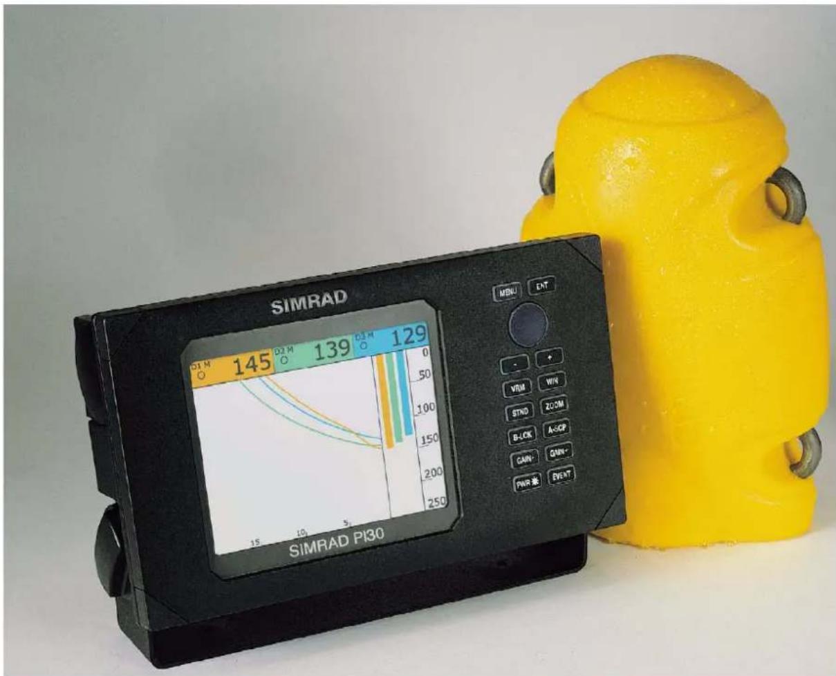
Simrad PI30
Purse seine instrumentation
www.simrad.com
Simrad PI30
Purse seine instrumentation Instruction manual
Note
Simrad AS makes every effort to ensure that the information contained within this document is correct. However, our equipment is continuously being improved and updated, so we cannot assume liability for any errors which may occur.
Warning
The equipment to which this manual applies must only be used for the purpose for which it was designed. Improper use or maintenance may cause damage to the equipment or injury to personnel. The user must be familiar with the contents of the appropriate manuals before attempting to operate or work on the equipment.
Simrad AS disclaims any responsibility for damage or injury caused by improper installation, use or maintenance of the equipment.
Copyright
©2000 Simrad AS
The information contained within this document remains the sole property of Simrad AS. No part of this document may be copied or reproduced in any form or by any means, and the information contained within is not to be communicated to a third party, without the prior written consent of Simrad AS.
Manufacturer:
Simrad AS
Strandpromenaden 50
P.O.Box 111
N-3191 Horten
Norway
Telephone: +47 33 03 40 00
Telefax: +47 33 04 29 87
Internet: www.simrad.com
E-mail: fish research@simrad.no
fish@simrad.no
Sections
This PI30 Purse seining system instruction manual describes how to install, operate and maintain the various system components and includes guidance for the attachment of PS30 depth and temperature sensors.
1 System description
2 Menus
3 Proceedurers
4 References
5 Troubleshooting
6 Maintenance and repair
7 Battery charging
8 System installation
9 Sensor configuration
10 Depth sensor attachment
11 Hydrophone installation
12 Technical specifications
13 Installation drawings
14 Glossary of terms
Remarks
The reader
This manual is intended to be used by the system's installer/operator.
The sections on system and hydrophone installation are intended for use by the installer/operator or shipyard engineers performing the installation. The information is supplied as the basis for the shipyard's own installation drawings for the vessel in question. On completion of the installation, this manual must be kept on board the vessel for reference purposes and system maintenance.
Tablire of contents
1 SYSTEM DESCRIPTION 1....
1.1 Overview 1.....
General 1.
System components 1
PI30 purse seine system primary functions 2
Derivable purse seine information 2
1.2 PI30 Display and control unit 2
General 2.
Display and control unit components 3
LCD display 3
Display and control unit keypad 4
1.3 PS30 Depth sensor 4
PS30 Temperature sensor 5
Sensor codes 5
Sensor charger 5
Hull mounted Hydrophone 5
Portable Hydrophone 6
1.4 Service and repair 6
2 MENUS 7
2.1 Viewing and selecting menus 7
General 7.
Menu navigation 7
3 PROCEDURES 9
3.1 Getting started 9
Power-up procedure 9
Power-down procedure 9
Master reset 9
Adjust LCD and keypad lighting 9
Selecting a display 10
Selecting and changing parameters 10
Display language 11
3.2 Display windows 11
Selecting the four display windows.... 11
Editing the four display windows 12
Manually changing display windows 12
Automatically changing the display window 12
To change the pre--selected time interval for window rotation 13
3.3 Purse seine functions 13....
Activating the numeric display 13.
Edit numeric display setup 14.
Activating the graphic display 15
Graphic display setup 15
Activating the status display 16
Status display setup 17
3.4 Nav functions 17
Activating the position display 17....
Resetting the log 18
Activating the navigation display 18
Navigation setup 19
3.5 Echo functions 20
General 20
Activating the echo display 21
Presentation setup 21
Activating bottom expansion 22
Presentation setup 23
Activating VRM expansion 24
Presentation setup 24
Turn A-scope ON / OFF 25
Turn VRM ON / OFF 25
Echo sounder setup 27
Editing parameters 27
3.6 Setup functions 28
Speed alarm, units & language 28....
Setup for Speed alarm, units & language 28
Interface setup NMEA 29
Setup of NMEA interface 30
Interface setup remote/alarm 31
Setup of remote/alarm interface 31
Sensor alarm/calibration 32
Setup for sensor alarm/calibration 32
Sensor calibration 33
Sensor configuration & receiver setup 34
Setup for sensor configuration & receiver 35
Display colour 36
Display colour palette setup 36
Master reset 37
Reset 38.... 38
4 REFERENCES 39.
4.1 Purse seine display references 39.....
Overview 39.
Numeric display with three depth sensor windows 39
Numeric display with two depth and one temperature sensor windows 40
Graphic Display 42
Graphic setup 43
Status display 44
4.2 Navigation display references 46
Overview 46.
Position display 46
Navigation display 48
4.3 Echo sounder display references 50
Overview 50.
General 51
Echo display 51
Bottom expansion 53
VRM expansion 54
A-scope 55
VRM 57
Echo sounder setup 57
4.4 PI30 Setup 58
Overview 58.
Speed alarm, units & language 58
Interface setup and NMEA connector 60
Interface setup remote/alarm 61
Sensor alarm/calibration 62
Sensor calibration 62
Sensor configuration & receiver setup 63
Sensor configuration & receiver parameters 65
Display colour 65
5 TROUBLESHOOTING 67
5.1 General PI30 information 67
5.2 PI30 Display and control cabinet 67
6 MAINTENANCE AND REPAIR 69
6.1 General 69
Service 69
Spare parts 69....69
6.2 PI30 Display and control cabinet 69....
Surface cleaning 69....
Electrical connections 69....
6.3 PS30 Hydrophone 69....
.Cleaning 69
Dry. dock 69
6.4 PS30 portable hydrophone 70
.Cleaning 70
Storage 70
6.5 PS30 Depth and temperature sensors 70
.Cleaning 70
Extra protection 70
7 BATTERY CHARGING AND TESTING 71
7.1 Charging PS30 sensors 71
General 71
When to charge the sensors 71
7.2 Charging procedure 71
7.3 Testing 73
Normal condition 73
Depleted battery 73
Possible fault 73
8 SYSTEM INSTALLATION 74
8.1 General 74
Planning 74
Cable 74
Sealed system 74
Grounding 74
Power source, fuse and power cable 74
8.2 PI30 display and control unit 74
Mounting 74
Bracket mounting 75
Mounting options 75
Flush mounting 76
8.3 Electrical connections 76
General 76
Power supply connections 76
Hydrophone connection 77
NMEA 0183 interface connections 77
Sensor configuration 77....
9 SENSOR CONFIGURATION 78....
General 78....
Necessary equipment 78.
9.1 Programming 78
PS30 Sensor Configuration Software 78
Connecting the PS30 sensor 81
Changing sensor configuration 81
9.2 Self-made programming cable 83
Required parts 83
Assembly procedure 83
10 DEPTH SENSOR ATTACHMENT 85
General 85.
Coverage 85
Attachment 85
Attaching depth sensors to the purse line 86
Attaching depth sensors to the bridle 87
Attaching depth sensors to the footrope 88
Attaching depth sensors to the footrope (tuna) 89
Attaching depth sensors to the net wall (tuna) 90
Conclusion 91
11 HYDROPHONE INSTALLATION 92
11.1 Overview 92
Hydrophone location 92.
Depth 92
Pounding danger 92
The boundary layer 92
Bulbous bow 93
Propeller noise 93
Bow/sternthruster noise 94
Noise from protruding objects and other sources 94
Optimal location 94
11.2 Hydrophone coverage area, horizontal orientation and tilt ..... 95
General 95.
Horizontal coverage area 95
Vertical coverage area 96
Tilt angle 96
11.3 Hydrophone mounting arrangement 97
General 97....
Keel mounted shoes 97....
Freestanding hydrophone in blister 98.
Dual hydrophone installation 99....
11.4 Portable hydrophone 101
11.5 Installation precautions 102
11.6 Cable layout 103
General 103
11.7 Cable specifications 103
Notes 106
12 TECHNICAL SPECIFICATIONS 108
12.1 General 108
12.2 Physical dimensions 108
12.3 Specifications 108
13 INSTALLATION DRAWINGS 112
14 GLOSSARY OF TERMS 123
Document reevisions
| Rev | Date | Written by | Checked by | Approved by |
| A 04.09.00 | LEA KR KR | |||
| B | ||||
| C | ||||
| D | ||||
| E | ||||
| F | ||||
| G |
(The original signatures are recorded in the company's logistic database.)
To assist us in making improvements to the product and to this manual, we would welcome comments and constructive criticism. Please send all such - in writing or by Email - to:

natural_image
Cartoon illustration of a hairy creature using a computer with a spear nearby (no text or symbols)Simrad AS Documentation Department P.O.Box 111 N-3191 Horten Norway or Email: dokavd@simrad.no
References
(The information on this page is intended for internal use.)
Documents
| Sect | Title | Loc. | File | P.no/Rev |
| 0 | P|30|nstruction manual | BA040 | 857-164148 | A |
| 1 | ||||
| 2 | ||||
| 3 |
Document history
A First edition for PIB30.
1 SYSTEM DESCRIPTION
1.1 Overview
General
The Simrad PI30 is an integration of proven marine technologies into a comprehensive tool specifically deigned for purse seining. This robust and maintenance-free monitoring system allows unparalleled control over the fishing operation by providing continuous, centralised information concerning the vessels position, gear and the environment at and below the water's surface.
System components
The PI30 Purse seine system is made up of a control and display unit, hydrophone and one or more sensors attached to the bottom of the net.
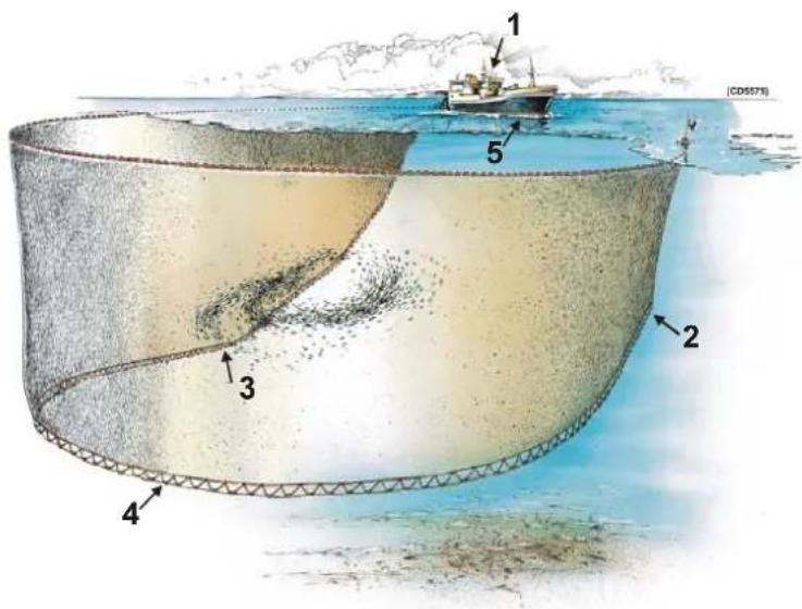
Figure 1 - PI30 components
1 PI30 Display and control unit
2 PS30 Depth sensor
3 PS30 Depth sensor
4 Optional PS30 temperature sensor
5 Hydrophone
The system is designed to be used with up to three sensors, optimally two depth sensors and one temperature sensor. Variations in this configuration may be made to suite individual needs.
PI30 p#p#seiseine system primary functions
The PI30 is a multi-functional instrument that has been designed to aid in the following:
•Purse seine monitoring
- Net depth at three locations or
- Water temperature and net depth at two locations
- Echo sounding*
- Water temperature at surface
- Water depth
- High resolution fishfinder - Bottom discrimination
- Navigation**
- Numerical GPS repeater
- Graphical track information
- Speed / Heading / Distance to WP / Time to WP / Cross track error
*Requires interface with an optional echo sounder transducer or triducer.
**Requires interface with an optional GPS.
Derivable purse seine information
Using the known relative location of the sensors attached to the purse seine, combined with the information they transmit, the following may be derived:
- When to begin pursuing.
•Optimal speed to purse.
•Risk of of pursuing over a school of fish.
- Risk net damage due to contact with the bottom.
- Risk ecological damage to the bottom and its inhabitants due to net contact or loss.
- Net sink rate.
- When the net has stopped sinking.
- When the net has started rising.
•Water temperature at different depths.
- When the net passes the thermo cline.
1.2 PI30 Display and control unit
General
The Display and control unit is a water-proof, marine grade electronic instrument incorporating an impact resistant polycarbonate front panel, die-cast aluminium housing and watertight electrical connections.
Display and control unit components
The PI30's electronics are sealed in the display and control unit allowing the it to be flush or bracket mounted in the wheelhouse or at an exposed control station.
![SIMRAD D1 [M] 116 3▲ D2 [M] 121 6▼ D3 [M] 109 2▼ SIMRAD PI30 MENU ENT - + VRM WIN STND ZOOM B-LCK A-SCP GAIN- GAIN+ PWR* EVENT](/content/2026/06/1315863/images/998ece9cc40325d152ef0c61ea699fd89aec697a6ccc4b8f1682c6f766045455.jpg)
Figure 2 - PI30 Display and control unit
LCD display
Computed information is displayed in both numerical and graphical form on the Liquid Crystal Display (LCD). The unit is programmed using drop-down menus and an integrated keypad. By pressing the keypad button WIN, you may manually or automatically choose between four preselected windows.

flowchart
graph TD
    A["LCD display"] --> B["Window 1 Numeric purse seine colour LCD"]
    A --> C["Window 2 Graphic purse seine colour LCD"]
    A --> D["Window 3 Echo sounder colour LCD"]
    A --> E["Window 4 Navigation LCD"]
    F["SIWRAD"] --> G["Control panel with +/- inputs"]
    H["Keypad"] --> I["Control panel with -/+, +, - inputs"]
    J["CDS: 1.9G"] --> K["Control panel with -/+, +, - inputs"]
    L["LCD display options"] --> M["Control panel with -/+, +, - inputs"]
Figure 3 - Display and control unit displays
Display and cocontrol unit keypad
The PI30 functions are quickly accessible using drop-down menus and the multi-direction button or directly from the keypad.

flowchart
graph TD
    A["MENU"] --> B["ENT"]
    C["MULTI-DIRECTION BUTTON"] --> D["MOVES: moves the cursor horizontally by pressing on its left or right side and vertically by pressing on its top or bottom."]
    E["VARIABLE RANGE MARKER"] --> F["+"]
    G["STANDARD"] --> H["+"]
    I["BOTTOM LOCK"] --> J["+"]
    K["GAIN-"] --> L["+"]
    M["POWER"] --> N["+"]
    O["PWR*"] --> P["+"]
    Q["VENT"] --> R["+"]
    S["INPUT"] --> T["+"]
    U["INPUT"] --> V["+"]
    W["INPUT"] --> X["+"]
    Y["INPUT"] --> Z["+"]
    AA["INPUT"] --> AB["+"]
    AC["INPUT"] --> AD["+"]
    AE["INPUT"] --> AF["+"]
    AG["INPUT"] --> AH["+"]
    AI["INPUT"] --> AJ["+"]
    AK["INPUT"] --> AL["+"]
    AM["INPUT"] --> AN["+"]
    AO["INPUT"] --> AP["+"]
    AQ["INPUT"] --> AR["+"]
    AS["INPUT"] --> AT["+"]
    AU["INPUT"] --> AV["+"]
    AW["INPUT"] --> AX["+"]
    AY["INPUT"] --> AZ["+"]
    BA["INPUT"] --> BB["+"]
    BC["INPUT"] --> BD["+"]
    BE["INPUT"] --> BF["+"]
    BG["INPUT"] --> BH["+"]
    BI["INPUT"] --> BJ["+"]
    BK["INPUT"] --> BL["+"]
    BM["INPUT"] --> BN["+"]
    BO["INPUT"] --> BP["+"]
    BQ["INPUT"] --> BR["+"]
    BS["INPUT"] --> BT["+"]
    BU["INPUT"] --> BV["+"]
    BW["INPUT"] --> BX["+"]
    BY["INPUT"] --> BZ["+"]
    CA["INPUT"] --> CB["+"]
    CC["INPUT"] --> CD["+"]
    CE["INPUT"] --> CF["+"]
    CG["INPUT"] --> CH["+"]
    CI["INPUT"] --> CJ["+"]
    CK["INPUT"] --> CL["+"]
    CM["INPUT"] --> CN["+"]
    CO["INPUT"] --> CP["+"]
    CS["INPUT"] --> CT["+"]
    CU["INPUT"] --> CV["+"]
    CW["INPUT"] --> CX["+"]
    CY["INPUT"] --> CZ["+"]
    DA["INPUT"] --> DB["+"]
    DC["INPUT"] --> DE["+"]
    DF["INPUT"] --> DG["+"]
    DH["INPUT"] --> DI["+"]
    DJ["INPUT"] --> DK["+"]
    DL["INPUT"] --> DV["+"]
    DW["INPUT"] --> DX["+"]
    DXN["INPUT"] --> DXB["+"]
    DXN --> DXC["-"]
    DXN --> DXD["-"]
    DXN --> DXE["-"]
    DXN --> DXF["-"]
    DXN --> DXG["-"]
    DXN --> DXH["-"]
    DXN --> DXI["-"]
    DXN --> DXJ["-"]
    DXN --> DXK["-"]
    DXN --> DXL["-"]
    DXN --> DXM["-"]
    DXN --> DXN["-"]
Figure 4 - Display and control unit keypad
1.3 PS30 Depth sensor
The PS30 Depth sensor is protected by a shock-absorbing, abrasion-resistant polyurethane shell and is designed to survive the extreme forces encountered at depth and while shooting and hauling a purse seine.

natural_image
Yellow plastic object with four black circular holes, resembling a stylized helmet or cushion (no text or symbols visible)Figure 5 - PI30 Depth sensor
Housed safely inside the unit are the electronics and self-contained power supply used to send depth information to the hydrophone connected by shielded cable to the display and control unit.
To further enhance sensor strength and avoid corrosion high grade titanium is used for all metal parts. The HyperYellow exterior colour provides maximum visibility to aid in retrieval. The compact design, quick update rate, extensive battery life and long-range transmission capability allows the PS30 Depth sensor to be used with any size net.
PS30 Temperature sensor
The PS30 Temperature sensor is physically identical to the PS30 Depth sensor with the exception that its function is to read and transmit the ambient water temperature.
Sensor codes
Differently coded signals for individual sensors are available to avoid interference from other vessels operating in the vicinity. Sensor codes can be programmed in the field using a computer.
Sensor charger
Three different Simrad sensor chargers are available depending on the vessel's main power supply:
• 220 VAC - Simrad sensor charger (reg. nr. 107-073189).
• 110 VAC - Simrad sensor charger (reg. nr. 107-073190).
• 24 VDC - Simrad sensor charger (reg. nr. 107-204060).

natural_image
Exterior view of a SIMRAD sensor charger connected to a white electrical plug and coiled cable (no text or symbols visible on main subject)Figure 6 - Simrad Sensor charger
Hull mounted Hydrophone
The hull mounted hydrophone has a 90^ horizontal beam and a 30^ vertical beam to provide the PI30 with optimal reception from the sensors. Its beam diagram makes it especially effective for use in purse seining and the wide coverage area reduces the need for careful alignment.
→ See figure 7.

natural_image
Coiled black cable with a red rectangular component attached, no visible text or symbolsFigure 77 Hull mounted hydrophone and cable
Portable Hydrophone
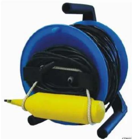
The portable hydrophone is designed as a temporary measure until a fixed hydrophone can be installed at the vessel's next planned dry docking. It has an omni-directional beam and a 50m integrated cable which is sheathed in polyurethane providing robust external protection to compliment its 150 kg tensile strength. The cable is supplied on a reel for convenient retrieval/stowage and is equipped with a plug for easy attachment to the control cabinet.
natural_image
Blue and yellow portable equipment with black cables and a yellow rubber strap (no text or symbols visible)Figure 8 - Portable hydrophone and cable stowed on reel
1.4 Service and repair
The PI30 Purse seine system does not contain any operator serviceable parts. Opening any of the system's components will void their respective warranties and touching internal electrical parts may cause bodily harm. Consult the chapter on troubleshooting if the system is not working properly or contact your authorized Simrad dealer for service and repair.
2 MEENUSS
2.1 Viewing and selecting menus
General
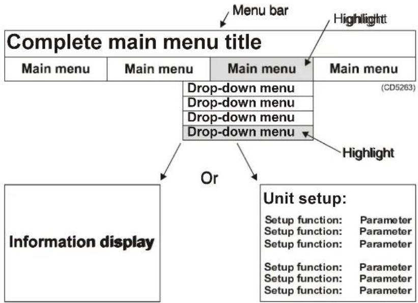
The menu bar is located across the top of the LCD and activated by pressing MENU. It is hidden when:
•anotherfunctionisselected
•MENU is pressed
•after 30 seconds of inactivity
Main and drop- down menus are highlighted when selected with the complete main menu title displayed in the top left-hand corner of the screen. Pressing ENT opens a drop- down menu's contents which may be a display or catalogue of setup parameters.
flowchart
graph TD
    A["Complete main menu title"] --> B["Main menu"]
    A --> C["Main menu"]
    A --> D["Main menu"]
    A --> E["Drop-down menu"]
    A --> F["Drop-down menu"]
    A --> G["Drop-down menu"]
    A --> H["Drop-down menu"]
    I["Information display"] --> J["Or"]
    K["Unit setup: Setup function: Parameter\nSetup function: Parameter\nSetup function: Parameter\nSetup function: Parameter\nSetup function: Parameter\nSetup function: Parameter"] --> L["Menu bar"]
    L --> M["Highlight"]
    N["(CD5263)"] --> O["Highlight"]
Figure 9 - Menu terminology and structure
Menus and catalogues of setup parameters are navigated using the MultifunctionButtonbypressing its top, bottom sides to move the on-screen cursor in the corresponding direction designating its position by highlighting.
Menu navigation
1 Press MENU to call up the menu bar.
- The last selected main menu will be highlighted and its complete name displayed in the top left-hand corner of the LCD.
2 PresPreENT activate the drop-down menu.
Or
3 Move the cursor to a different main menu which automatically activates the corresponding drop-down menu.
- Pressing the Multi-direction button's top, bottom or sides moves the on-screen cursor in the corresponding direction designating its position by highlighting.
4 Move the cursor to the desired drop-down menu.
5 Press ENT to display its contents.
- This hides the menu bar and activates a display or a catalogue of parameters.
6 Press MENU to call up the menu bar and proceed to the next function.
3 PROCEDURE PRESS
3.1 Getting started
Power--up procedure
1 Press and hold PWR until a the message "SIMRAD WELCOME TO PI30" appears on the LCD.
- The function selected when the unit was last powered-up is displayed.
Power--down procedure
1 Press PWR to call up the Light and power menu.
2 Press and hold PWR until the unit "beeps" and the LCD is blank.
Master reset
1 Press MENU to call up the menu bar.
2 If SETUP is displayed in the top left-hand corner of the LCD press ENT to activate its drop-down menu. If it is not displayed, move the cursor to the SETUP main menu which will automatically activate its drop-down menu.
3 Move the cursor to the Master reset drop-down menu.
4 Press ENT to activate.
5 Press the top of the Multi-direction button.
6 Press the bottom of the Multi-direction button.
7 Press ENT.
- The unit will be returned to factory presets.
8 Press MENU to call up the menu bar and proceed to the next function.
Adjust LCD and keypad lighting
1 Press PWR to call up the Light and power menu:
- Light - adjusts LCD light/contrast.
- Keypad light - adjusts keypad lighting.
- Display colour - compensates for ambient light. DAY(1) for daytime and NIGHT (2) for nighttime operation.
2 Move the cursor to the parameter to be changed:
- Pressing the top or bottom of the Multi-direction button moves the on-screen cursor in the corresponding direction designating its position by highlighting.
3 Press the left or right sides of the Multi-direction button to adjust the parameters as desired.
4 Press MENU to exit the Light and power menu or press and hold PWR until the unit "beeps" and the LCD is blank to power-down.
Selecting a display
1 Press MENU to call up the menu bar.
- The last selected main menu will be highlighted and its complete name displayed in the top left-hand corner of the LCD.
2 Press ENT to activate the drop-down menu.
Or
3 Move the cursor to a different main menu which automatically activates the corresponding drop-down menu.
- Pressing the Multi-direction button's top, bottom or sides moves the on-screen cursor in the corresponding direction designating its position by highlighting.
4 Move the cursor to one of the display windowoptions inthe drop-down menu.
5 Press ENT to activate the display.
6 Press MENU to call up the menu bar to proceed to an other function.
Or
7 Press WIN to change the display window.
Selecting and changing parameters
1 Press MENU to call up the menu bar.
- The last selected main menu will be highlighted and its complete name displayed in the top left-hand corner of the LCD.
2 Press ENT to activate the drop-down menu.
Or
3 Move the cursor to a different main menu which automatically activates the corresponding drop-down menu.
- Pressing the Multi-direction button's top, bottom or sides moves the on-screen cursor in the corresponding direction designating its position by highlighting.
4 Move the cursor to one of the options in the drop-down menu.
5 President display its contents.
- This hides the menu bar and activates the catalogue of parameters.
6 Press ENT to open the parameters for editing.
- The cursor is now designated by a red box and moved using the Multi-direction button.
7 Move the cursor to the parameter to be changed.
8 Press + or - to change the parameter's value or status.
9 Repeat step 7 and 8 until all desired changes have been made.
10 Press ENT to confirm the changes.
- Set parameters will not be lost even if the unit is switched off or the power supply disconnected.
11 Press MENU to call up the menu bar to proceed to an other function.
Or
12 Press WIN to set the displayed catalogue of parameter as one of the four display windows and enter into the rotation.
Display language
1 Press MENU to call up the menu bar.
2 If the Setup menu is highlighted press ENT, otherwise move the cursor to the Setup menu.
3 Move the cursor to the Speed alarm, units & language drop-down menu.
4 Press ENT to display its contents.
- This hides the menu bar and activates the catalogues Setup for Speed and Setup for Units.
5 Press ENT to open their parameters for editing.
6 Move the cursor to Display text in.
7 Press + or - to change to the desired language.
8 Press ENT to confirm the change.
9 Press MENU to call up the menu bar to proceed to an other function.
3.2 Display windows
Selecting the four display windows
1 Press MENU to call up the menu bar.
2 Move the thersons to select a main menu.
3 Move the cursor to one of the options in the drop-down menu.
4 Press ENT to display its contents.
5 Press WIN to enter the display in the four window rotation.
6 Repeat steps 1 through 5 three more times selecting a different display each time.
- The windows will be displayed in the sequence they were selected.
- One or more window may be duplicated to reduce the number of different windows in the rotation.
- Any of the drop-down menu options may be selected as one of the windows in the rotation.
Editing the four display windows
1 If activated, stop the automatic rotation of pre-selected windows by pressing WIN.
2 Press WIN unit the window to be replaced is displayed on the LCD.
3 Press MENU to call up the menu bar.
4 Move the cursor to select a main menu.
5 Move the cursor to one of the options in the drop-down menu.
6 Press ENT to display its contents.
7 Press WIN to enter the new display in the four window rotation.
Manually changing display windows
1 Press WIN successively to change the display window.
- Each time WIN is pressed one of the four windows in the pre-selected rotation will be displayed.
Automatically changing the display window
1 Press and hold WIN for two seconds to start the automatic rotation of pre-selected windows.
2 Press Win to return to manual operation.
Or
1 Press MENU to call up the menu bar.
2 If the Setup menu is highlighted press ENT, otherwise move the cursor to the Setup menu.
3 Move the torsorsto the Speed alarm, units & language drop-down menu.
4 Press ENT to display its contents.
5 Press ENT to open the parameters for editing.
6 Move the cursor to WIN change interval.
7 Press + or - to select MANUAL or AUTO.
8 Press ENT to confirm the change.
9 Press MENU to call up the menu bar to proceed to an other function.
To change the pre--selected time interval for window rotation
1 Press MENU to call up the menu bar.
2 If the Setup menu is highlighted press ENT, otherwise move the cursor to the Setup menu.
3 Move the cursor to the Speed alarm, units & language drop-down menu.
4 Press ENT to display its contents.
5 Press ENT to open their parameters for editing.
6 Move the cursor to WIN change interval.
7 Press + or - to increase or decrease the time interval.
8 Press ENT to confirm the change.
9 Press MENU to call up the menu bar to proceed to an other function.
3.3 Purse seine functions
Activating the numeric display
1 Press MENU to call up the menu bar.
→ See figure 10.
2 If PURSE SEINE is displayed in the top left-hand corner of the LCD press ENT to activate its drop-down menu. If it is not displayed, move the cursor to the PURSE SEINE main menu which will automatically activate its drop-down menu.
3 Move the cursor to the Numeric display drop-down menu.
4 Press ENT to activate.
→ See figure 11.
| PURSE SEINE | |||
| PURSE SEINE | NAV | ECHO | SETUP |
| Numeric display | (CD5264) | ||
| Graphic display | |||
| Status display | |||
Figure 100- NuNumeric display drop-down menu selected
Edit numeric display setup
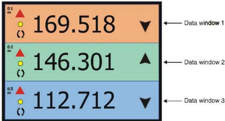
Activating the Numeric display window will hide the menu bar and fill the LCD with information received from the (three) PS30 sensors attached to the net.
bar
| Category | Value | |---|---| | D1 m | 169.518 | | D2 m | 146.301 | | D3 m | 112.712 | ← Data window 1 ← Data window 2 ← Data window 3Figure 11 - Numeric display window
1 Press ENT with the Numeric display window open to activate the Numeric setup catalogue of parameters.
→ See figure 12.
- The cursor is now designated by a red box and moved using the Multi-direction button.
2 Move the cursor to the parameter to be changed.
3 Press + or - to change the parameter's value or status.
4 Repeat steps 2 and 3 until all desired changes have been made.
5 Press ENT to confirm the changes and return to the Numeric display window.
- The Numeric display setup parameters will not be lost even if the unit is switched off or the power supply disconnected.

Figure 122 - Numeric display setup window
Activating the graphic display
1 Press MENU to call up the menu bar.
→See figure 13.
2 If PURSE SEINE is displayed in the top left-hand corner of the LCD press ENT to activate its drop-down menu. If it is not displayed, move the cursor to the PURSE SEINE main menu which will automatically activate its drop-down menu.
3 Move the cursor to the Graphic display drop-down menu.
4 Press ENT to activate.
→See figure 14.
| PURSE SEINE | |||
| PURSE SEINE | NAV | ECHO | SETUP |
| Numeric display | (CD5273) | ||
| Graphic display | |||
| Status display | |||
Figure 13 - Graphic display drop-down menu selected
Graphic display setup
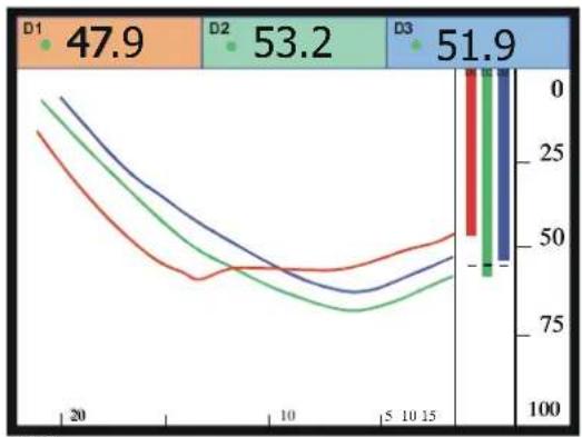
Activating the Graphic display window will hide the menu bar and fill the LCD with information received from the (three) PS30 sensors attached to the net.
1 Press ENT with the Graphic display window open to activate the Graphic setup catalogue of parameters.
→See figure 15.
- The cursor is now designated by a red box and moved using the Multi-direction button.
2 Move the cursor to the parameter to be changed.
3 Press + or - to change the parameter's value or status.
line
| Group | Value | |-------|-------| | D1 | 47.9 | | D2 | 53.2 | | D3 | 51.9 |Figure 14 - Graphic display window
4 Repeat steps 2 and 3 until all desired changes have been made.
5 Press ENT to confirm the changes and return to the Graphic display window.
- The Graphic display setup parameters will not be lost even if the unit is switched off or the power supply disconnected.
| Graphic setup: | |
| Superimpose echo sounder: | NO |
| Scroll speed: | LOW |
| Depth bars: | ON |
| Depth grid: | OFF |
| Temperature marker: | OFF |
| Temperature scale: | OFF |
| Graph line thickness: | 3 |
(CD5267)
Figure 15 - Graphic display setup window
Activating the status display
1 Press MENU to call up the menu bar.
→ See figure 16.
2 If PURSE SEINE is displayed in the top left-hand corner of the LCD press ENT to activate its drop-down menu. If it is not displayed, move the cursor to the PURSE SEINE main menu which will automatically activate its drop-down menu.
3 Move the cursor to the Status display drop-down menu.
4 Press ENT to activate.
→ See figure 17.
| PURSE SEINE | |||
| PURSE SEINE | NAV | ECHO | SETUP |
| Numeric display | (CD5275) | ||
| Graphic display | |||
| Status display | |||
Figure 106 StaStatus display drop-down menu selected
Status display setup
Activating the Status display window will hide the menu bar and fill the LCD with a matrix of information from several sources including the (three) PS30 sensors attached to the net, speed log*, GPS*, echo sounder* and triducer*.
*If interfaced with the PI30.

bar
| Category | Value | |---|---| | MP Filter: OFF. | 47.9 | | D2 m | 53.2 | | D3 m | 51.9 | | SW: 0.16 / 0.15 / 0.30 Ch/R: 16. E: 0 Gain dB Ch 10 Ch 16h 16 Ch 30h 30 COG: * ° STW: *. * kn Surface: *. * ° C CD5261Figure 17 - Status display window
Pressing ENT with the Status display window open will have no effect. Individual setup parameters must be accessed via the Sensor configuration and receiver setup window.
3.4 Nav functions
Activating the position display
1 Press MENU to call up the menu bar.
→ See figure 18.
2 If NAVIGATION is displayed in the top left-hand corner of the LCD press ENT to activate its drop-down menu. If it is not displayed, move the cursor to the NAV main menu which will automatically activate its drop-down menu.
3 Move the cursor to the Position display drop-down menu.
4 Press ENT to activate.
→ See figure 19.
| NAVIGATION | |||
| PURSE SEINE | NAV | ECHO | SETUP |
| Position display | (CD5283) | ||
| Navigation display | |||
Figure 188 PosPosition display drop-down menu selected
Resetting the log
Activating the Position display window will hide the menu bar and fill the LCD with information received from the GPS.
| Status No valid POS | Log 1 0.0nm | Log 2 0.0nm |
| LAT 56å53.000 N LON 9å50.000 E | ||
| Speed *.* Kn | Course * Å | Depth *.* m |
| Water temp. *.* Cå | Local time 00:00:00 | Local date 0-0-0000 |
Figure 19 - Position display window
1 Press ENT with the Position display window open to activate the Reset log function.
→ See figure 20.
- The cursor is now designated by a red box and moved using the Multi-direction button.
2 Move the cursor to the parameter to be changed.
3 Press + or - to change the parameter's value.
4 Repeat steps 2 and 3 until all desired changes have been made.
5 Press ENT to confirm the changes and return to the Position display window.
- The Reset log parameters will not be lost even if the unit is switched off or the power supply disconnected.
Activating the navigation display
1 Press MENU to call up the menu bar.
→ See figure 21.
2 If NAVIGATION is displayed in the top left-hand corner of the LCD press ENT to activate its drop-down menu. If it is not displayed, move the cursor to the NAV main menu which will automatically activate its drop- down menu.

Figure 200 - Reset log window
3 Move the cursor to the Navigation display drop-down menu.
4 Press ENT to activate.
→See figure 22.
| NAVIGATION | |||
| PURSE SEINE | NAV | ECHO | SETUP |
| Position display | (CD5285) | ||
| Navigation display | |||
Figure 21 - Navigation display drop-down menu selected
Navigation setup
Activating the Navigation display window will hide the menu bar and fill the LCD with information received from the GPS.
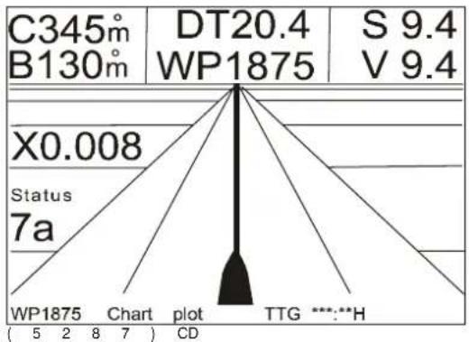
Figure 22 - Navigation display window
1 Press ENT with the Navigation display window open to activate the Navigation setup catalogue of parameters.
→See figure 23.
- The cursor is now designated by a red box and moved using the Multi-direction button.
2 Move the cursor to the parameter to be changed.
3 Press + or - to change the parameter's value or status.
4 Repeat-step2 and 3 until all desired changes have been made.
5 Press ENT to confirm the changes and return to the Navigation display window.
- The Navigation setup parameters will not be lost even if the unit is switched off or the power supply disconnected.
Navigation setup:
Course & bearing as: MAGNETIC XTE alarm distance: 0.50nm
Figure 23 - Navigation setup window
(CD5286)
3.5 Echo functions
General
The PI30 has two different Echo sounder drop-down menus available. The complete drop-down menu is made up of six choices and the abbreviated version is made up of four.
→ See figure 24.
The abbreviated Echo sounder drop-down menu is displayed when the unit is turned on for the first time or after being reset using the Master reset function. To replace the abbreviated drop-down menu with the complete version:
1 Press MENU to call up the menu bar.
2 If ECHO SOUNDER is displayed in the top left-hand corner of the LCD press ENT to activate its drop-down menu. If it is not displayed, move the cursor to the ECHO main menu which will automatically activate its drop-down menu.
3 Move the cursor to the Echo display drop-down menu.
4 Press ENT to activate.
5 Press MENU.
6 Press ENT.
- The complete Echo sounder drop-down menu is now displayed.
| ECHO SOUNDER | |||
| PURSE SEINE | NAV | ECHO | SETUP |
| Echo display | |||
| Bottom expansion | |||
| VRM expansion | |||
| Turn A-scope ON | |||
| Tum VRMON | |||
| Echo sounder setup | |||
| ECHO SOUNDER | |||
| PURSE SEINE | NAV ECHO | SETUP | |
| Echo display | (CD5328) | ||
| Bottom expansion | |||
| VRM expansion | |||
| Echo sounder setup | |||
Figure 24 Gom Complete and abbreviated Echo sounder drop-down menus
Activating the echo display
1 Press MENU to call up the menu bar.
→See figure 25.
2 If ECHO SOUNDER is displayed in the top left-hand corner of the LCD press ENT to activate its drop-down menu. If it is not displayed, move the cursor to the ECHO main menu which will automatically activate its drop-down menu.
3 Move the cursor to the Echo display drop-down menu.
4 Press ENT to activate.
→See figure 26.
| ECHO SOUNDER | |||
| PURSE SEINE | NAV | ECHO | SETUP |
| Echo display | (CD5276) | ||
| Bottom expansion | |||
| VRM expansion | |||
| Turn A-scope ON | |||
| Turn VRM ON | |||
| Echo sounder setup | |||
Figure 25 - Echo display drop-down menu selected
Presentation setup
Activating the Echo display window will hide the menu bar and fill the LCD with information received from the echo sounder.

area
| Depth (m) | Value | |---|---| | 0 | 50.0 | | 25 | 75 | | 50 | 100 | | 75 | 100 | | 100 | 100 | | T | 17.3°C | | D | 71.3 m |Figure 206- EchEcho display window
1 Press ENT with the Echo display window open to activate the Presentation setup catalogue of parameters.
→See figure 27.
- The cursor is now designated by a red box and moved using the Multi-direction button.
2 Move the cursor to the parameter to be changed.
3 Press + or - to change the parameter's value or status.
4 Repeat steps 2 and 3 until all desired changes have been made.
5 Press ENT to confirm the changes and return to the Echo display window.
- The Presentation setup parameters will not be lost even if the unit is switched off or the power supply disconnected.
| Presentation setup: | |
| Range start: | 000 m |
| Range: | 250 m |
| Gain: | 31.0dB |
| Scroll speed: | LOW |
| White line: | OFF |
| Expansion window: | 6 m |
| TVG: | Fish (40 log R) |
| Sound speed: | 1470m/s |
| Ping to ping filter: | ON |
| Signal threshold: | OFF |
| Colour threshold: | OFF |
| Depth grid: | OFF |
| Echo sounder frequency: | 50kHz |
Figure 27 - Presentation setup window
(CD5277)
Activating bottom expansion
1 Press MENU to call up the menu bar.
→See figure 28.
2 If ECHO SOUNDER is displayed in the top left-hand corner of the LCD press ENT to activate its drop-down menu. If it is not displayed, move the cursor to the ECHO main menu which will automatically activate its drop-down menu.
3 Move the cursor to the Bottom expansion drop-down menu.
4 Press ENT to activate.
→See figure 29.
| ECHO SOUNDER | |||
| PURSE SEINE | NAV | ECHO | SETUP |
| Echo display | (CD5278) | ||
| Bottom expansion | |||
| VRM expansion | |||
| TumA -scop e ON | |||
| Turn VRM ON | |||
| Echo sounder setup | |||
Figure 28 - Bottom expansion drop-down menu selected
Presentation setup
Activating the Bottom expansion window will hide the menu bar and fill the LCD with information received from the echo sounder.

area
| Depth (m) | Value | | --------- | ----- | | 0 | 29.3 | | 25 | | | 50 | | | 75 | | | 100 | | | -10 | | | 0 | +10 | | +10 | |Figure 29 - Bottom expansion window
1 Press ENT with the Bottom expansion window open to activate the Presentation setup catalogue of parameters.
→See figure 27 on page 22.
- The cursor is now designated by a red box and moved using the Multi-direction button.
2 Move the cursor to the parameter to be changed.
3 Press + or - to change the parameter's value or status.
4 Repeat steps 2 and 3 until all desired changes have been made.
5 Press ENT to confirm the changes and return to the Bottom expansion window.
- The Presentation setup parameters will not be lost even if the unit is switched off or the power supply disconnected.
Activating VARM expansion
1 Press MENU to call up the menu bar.
→See figure 30.
2 If ECHO SOUNDER is displayed in the top left-hand corner of the LCD press ENT to activate its drop-down menu. If it is not displayed, move the cursor to the ECHO main menu which will automatically activate its drop-down menu.
3 Move the cursor to the VRM expansion drop-down menu.
4 Press ENT to activate.
→See figure 31.
| ECHO SOUNDER | |||
| PURSE SEINE | NAV | ECHO | SETUP |
| Echo display | (CD5279) | ||
| Bottom expansion | |||
| VRM expansion | |||
| Turn A-scope ON | |||
| Turn VRM ON | |||
| Echo sounder setup | |||
Figure 30 - VRM expansion drop-down menu selected
Presentation setup
Activating the VRM expansion window will hide the menu bar and fill the LCD with information received from the echo sounder.

geo
| Depth (m) | Value | | --------- | ----- | | 0 | +10 | | 25 | 71 | | 50 | 75 | | 75 | 70 | | 100 | 100 | | 125 | -10 | | 150 | 71 | | 17.3 | 75 | | D | 71.0 |Figure 31 - VRM expansion window
1 Press ENT with the Bottom expansion window open to activate the Presentation setup catalogue of parameters.
→See figure 27 on page 22.
- The cursor is now designated by a red box and moved using the Multi-direction button.
2 Move the cursor to the parameter to be changed.
3 Press + or - to change the parameter's value or status.
4 Repeat step2 and 3 until all desired changes have been made.
5 Press ENT to confirm the changes and return to the VRM expansion window.
- The Presentation setup parameters will not be lost even if the unit is switched off or the power supply disconnected.
Turn A--scope ON / OFF
1 Press MENU to call up the menu bar.
→ See figure 32.
2 If ECHO SOUNDER is displayed in the top left-hand corner of the LCD press ENT to activate its drop-down menu. If it is not displayed, move the cursor to the ECHO main menu which will automatically activate its drop-down menu.
3 Move the cursor to the Turn A-scope ON/OFF drop-down menu.
4 Press ENT to either turn the A-scope on if it is displayed as OFF in the drop down menu, or off if it is ON.
→ See figure 33.
| ECHO SOUNDER | |||
| PURSE SEINE | NAV | ECHO | SETUP |
| Echo display | (CD5281) | ||
| Bottom expansion | |||
| VRM expansion | |||
| Turn A-scope ON | |||
| Turn VRM ON | |||
| Echo sounder setup | |||
Figure 32 - Turn A-scope ON / OFF drop-down menu selected A-scope keypad
The A-scope function may also be activated or deactivated by pressing the A-SCP keypad when either the Echo display, Bottom expansion or VRM expansion windows are open.
Turn VRM ON / OFF
1 Press MENU to call up the menu bar.
→ See figure 34.
2 If ECHO SOUNDER is displayed in the top left-hand corner of the LCD press ENT to activate its drop-down menu. If it is not displayed, move the cursor to the ECHO main menu which will automatically activate its drop-down menu.
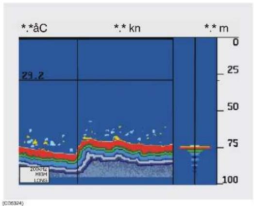
area
| Depth (m) | Value | | --------- | ----- | | 0 | 29.2 | | 25 | | | 50 | | | 75 | | | 100 | |Figure 333 - A-scope function activated
3 Move the cursor to the Turn VRM ON / OFF drop-down menu.
4 Press ENT to either turn the VRM on if it is displayed as OFF in the drop down menu, or off if it is ON.
→See figure 35.
| ECHO SOUNDER | |||
| PURSE SEINE | NAV | ECHO | SETUP |
| Echo display | (CD5329) | ||
| Bottom expansion | |||
| VRM expansion | |||
| Turn A -scope ON | |||
| Turn VRM ON | |||
| Echo sounder setup | |||
Figure 34 - Turn VRM ON / OFF drop-down menu selected
VRM keypad
The VRM function may also be activated or deactivated by pressing the VRM keypad when either the Echo display or Bottom expansion windows are open. The range is adjusted using the - and + keypads.

bar_stacked
| Depth (km) | Layer Color | Value | |------------|-------------|-------| | 0 | Blue | 50.0 | | 25 | Red | 200 kHz | | 50 | Green | 50.0 | | 75 | Yellow | 75.0 | | 100 | Light Blue | 100 |Figure 35 - VRM set at 50.0m
Echo sounderssetup
1 Press MENU to call up the menu bar.
→See figure 36.
2 If ECHO SOUNDER is displayed in the top left-hand corner of the LCD press ENT to activate its drop-down menu. If it is not displayed, move the cursor to the ECHO main menu which will automatically activate its drop-down menu.
3 Move the cursor to the Echo sounder setup drop-down menu.
4 Press ENT to activate.
→See figure 37.
| ECHO SOUNDER | |||
| PURSE SEINE | NAV | ECHO | SETUP |
| Echo display | (CD5330) | ||
| Bottom expansion | |||
| VRM expansion | |||
| Turn A-scope ON | |||
| Turn VRM ON | |||
| Echo sounder setup | |||
Figure 36 - Echo sounder setup drop-down menu selected
Editing parameters
Activating the Echo sounder setup window will hide the menu bar and fill the LCD with the catalogue of setup parameters.
| Echo sounder setup: | |
| Transducer depth below surface: | 0.0 m |
| Keel depth below surface | 0.0 m |
| Display: | DEPTH BELOW SURFACE |
| Alarm for fish: | Strength: 30dB OFF |
| Depth for fish: | min: 10 m max: 100 m |
| Depth alarm maximum: | 100 m OFF |
| Depth alarm minimum: | 10 m OFF |
| Transmitter: | AUTO |
| Transmit pulse length: | AUTO |
| Echo sounder mode: | OFF |
(CD5282)
Figure 37 - Echo sounder setup window
1 Press ENT.
- The cursor is now designated by a red box and moved using the Multi-direction button.
2 Move the cursor to the parameter to be changed.
3 Press + or - to change the parameter's value or status.
4 Repeat steps 2 and 3 until all desired changes have been made.
5 President confirm the changes.
- The Echo sounder setup parameters will not be lost even if the unit is switched off or the power supply disconnected.
6 Press MENU to call up the menu bar and proceed to the next function.
3.6 Setup functions
Speed alarm, units & language
1 Press MENU to call up the menu bar.
→ See figure 38.
2 If SETUP is displayed in the top left-hand corner of the LCD press ENT to activate its drop-down menu. If it is not displayed, move the cursor to the SETUP main menu which will automatically activate its drop-down menu.
3 Move the cursor to the Speed alarm, units & language drop-down menu.
4 Press ENT to activate.
→ See figure 39.
| SETUP | |||
| PURSE SEINE | NAV | ECHO | SETUP |
| (CD5289) | Speed alarm, units & language | ||
| Interface setup NMEA | |||
| Interface setup remote/alarm | |||
| Sensor alarm/calibration | |||
| Sensor config & receiver setup | |||
| Display colour | |||
| Master reset | |||
Figure 38 - Speed alarm, units & language drop-down menu selected
Setup for Speed alarm, units & language
Activating the Speed alarm, units & language window will hide the menu bar and fill the LCD with the catalogue of setup parameters.
1 Press ENT.
- The cursor is now designated by a red box and moved using the Multi-direction button.
2 Move the cursor to the parameter to be changed.
| Setup for speed: | |
| LOG speed sensor: | OFF |
| LOG speed calibration: | 19000 PULSES/nm |
| Speed alarm maximum: | 0.0 kn OFF |
| Speed alarm minimum: | 0.0 kn OFF |
| Setup for units: | |
| Depth in: | METERS |
| Distance in: | NAUTICAL MILES |
| Speed in: | KNOTS |
| Temperature in: | DEGREE CELSIUS |
| Software version: | PI30 0.12 |
| DSP: 0.00. MC: 0.00 | |
| WIN change interval: | 5 sec. MANUAL |
| Display test in: | English GB |
(5300)CD
Figure 399- Set Setup for Speed alarm, units & language window
3 Press + or - to change the parameter's value.
4 Repeat steps 2 and 3 until all desired changes have been made.
5 Press ENT to confirm the changes.
- The Speed alarm, units & language setup parameters will not be lost even if the unit is switched off or the power supply disconnected.
6 Press MENU to call up the menu bar and proceed to the next function.
Interface setup NMEA
1 Press MENU to call up the menu bar.
→ See figure 40.
2 If SETUP is displayed in the top left-hand corner of the LCD press ENT to activate its drop-down menu. If it is not displayed, move the cursor to the SETUP main menu which will automatically activate its drop-down menu.
3 Move the cursor to the Interface setup NMEA drop-down menu.
4 Press ENT to activate.
→ See figure 41.
| SETUP | |||
| PURSE SEINE | NAV | ECHO | SETUP |
| (CD5301) | Speed alarm, units & language | ||
| Interface setup NMEA | |||
| Interface setup remote/alarm | |||
| Sensor alarm/calibration | |||
| Sensor config & receiver setup | |||
| Display colour | |||
| Master reset | |||
Figure 40 - Interface setup NMEA drop-down menu selected
Setup offNMMA interface
Activating the Interface setup NMEA window will hide the menu bar and fill the LCD with the catalogue of setup parameters.
| Interface setup NMEA: | ||
| Input pin (3,4): | NMEA0183 | |
| Position: | GLL ON | |
| Course: | VTG ON | |
| Speed: | VTG ON | |
| Navigation (APB, RMB and XTE): | ON | |
| Water temperature: | MTW ON | |
| Output pin (1,2): | NMEA0183 | |
| DBK ON | DBS OFF | DBT OFF |
| DPT ON | MTW ON | VHW ON |
| Output pin (1,2): | DATA FROM DSP | |
| Configuration (PSIMP,C): | ON | |
| Data (PSIMP,D): | ON | |
| Sensor definition (PSIMP,F): | ON | |
| Frequency spectrum (PSIMP,S): | ON | |
| Transit (PSIMP,T): | ON | |
(5302)CD
Figure 41 - Interface setup NMEA window
1 Press ENT.
- The Interface setup NMEA window will be hidden and the LCD filled with the warning: "You are about to change settings for NMEA interface".
→ See figure 42.
Warning!
You are about to change settings for NMEA interface
ESCAPE: MENU PROCEED: ENT
Figure 42 - NMEA warning window
(5303)CD
2 Press ENT.
- The warning will be replaced by the Interface setup NMEA window and the cursor is now designated by a red box and moved using the Multi-direction button.
3 Move the cursor to the parameter to be changed.
4 Press + or - to change the parameter's value.
5 Repeat steps 3 and 4 until all desired changes have been made.
6 Press ENT to confirm the changes.
- The Interface setup MNEA parameters will not be lost even if the unit is switched off or the power supply disconnected.
7 Press MENU to call up the menu bar and proceed to the next function.
Interface setup remote/alarm
1 Press MENU to call up the menu bar.
→See figure 43.
2 If SETUP is displayed in the top left-hand corner of the LCD press ENT to activate its drop-down menu. If it is not displayed, move the cursor to the SETUP main menu which will automatically activate its drop-down menu.
3 Move the cursor to the Interface setup remote/alarm drop-down menu.
4 Press ENT to activate.
→See figure 44.
| SETUP | |||
| PURSE SEINE | NAV | ECHO | SETUP |
| (CD5304) | Speed alarm, units & language | ||
| Interface setup NMEA | |||
| Interface setup remote/alarm | |||
| Sensor alarm/calibration | |||
| Sensor config & receiver setup | |||
| Display colour | |||
| Master reset | |||
Figure 43 - Interface setup remote alarm drop-down menu selected
Setup of remote/alarm interface
Activating the Interface setup remote/alarm window will hide the menu bar and fill the LCD with the catalogue of setup parameters.
| Interface setup remote/alarm: | |
| Input pin (3,4): | NMEA0183 |
| Position: | GLL OFF |
| Course: | VTG OFF |
| Speed: | VTG OFF |
| Navigation (APB, RMB and XTE): | OFF |
| Water temperature: | MTW OFF |
| Interface setup alarm: | |
| Output pin (5,2): | ALARM ON |
| Alarm stand-by level: | LOW |
(CD5305)
Figure 44 - Interface setup remote/alarm window
1 Press ENT.
- The Interface setup remote/alarm window will be hidden and the LCD filled with the warning: "You are about to change settings for NMEA interface".
→See figure 42 on page 30.
2 PresPSENT.
- The warning will be replaced by the Interface setup remote/alarm window and the cursor is now designated by a red box and moved using the Multi-direction button.
3 Move the cursor to the parameter to be changed.
4 Press + or - to change the parameter's value.
5 Repeat steps 3 and 4 until all desired changes have been made.
6 Press ENT to confirm the changes.
- The Interface setup remote/alarm parameters will not be lost even if the unit is switched off or the power supply disconnected.
7 Press MENU to call up the menu bar and proceed to the next function.
Sensor alarm/calibration
1 Press MENU to call up the menu bar.
→ See figure 45.
2 If SETUP is displayed in the top left-hand corner of the LCD press ENT to activate its drop-down menu. If it is not displayed, move the cursor to the SETUP main menu which will automatically activate its drop-down menu.
3 Move the cursor to the Sensor alarm/calibration drop-down menu.
4 Press ENT to activate.
→ See figure 46.
| SETUP | |||
| PURSE SEINE | NAV | ECHO | SETUP |
| (CD5309) | Speed alarm, units & language | ||
| Interface setup NMEA | |||
| Interface setup remote/alarm | |||
| Sensor alarm/calibration | |||
| Sensor config & receiver setup | |||
| Display colour | |||
| Master reset | |||
Figure 45 - Sensor alarm/calibration drop-down menu selected
Setup for sensor alarm/calibration
Activating the Sensor alarm/calibration window will hide the menu bar and fill the LCD with the catalogue of setup parameters.
| Alarm setup: | |||
| Depth 1: min: 0 m OFF. Max: 300 m OFF | |||
| Depth 2: min: 0 m OFF. Max: 300 m OFF | |||
| Depth 3: min: 0 m OFF. Max: 300 m OFF | |||
| Depth sensor: | |||
| Calibration: NO | |||
| Offset: D1:0.0 m D2:0.0 m D3:0.0 m |
Figure 446 - Sensor alarm/calibration window
1 Press ENT.
- The cursor is now designated by a red box and moved using the Multi-direction button.
2 Move the cursor to the parameter to be changed.
3 Press + or - to change the parameter's value.
4 Repeat steps 2 and 3 until all desired changes have been made.
5 Press ENT to confirm the changes.
- The Sensor alarm/calibration parameters will not be lost even if the unit is switched off or the power supply disconnected.
6 Press MENU to call up the menu bar and proceed to the next function.
Sensor calibration
Sensors are calibrated at Simrad before shipment, but may be calibrated at any time on board the vessel. The reference level (distance from the surface of the water to the sensor) used as the basis for depth calculations may be changed from the default setting of 1.0 m to + or - 9.9 m.
Sensors may be calibrated simultaneously (or individually) as follows:
1 Suspend the sensors one meter below the water's surface, the vessel's draft plus one meter or the depth to be used as the reference point which will be displayed as one meter on the LCD. Offset values can also be entered directly, but is not recommended.
2 Energise the PI30 Display and control unit and open the Sensor alarm/calibration window.
3 Note the displayed offset values for each of sensors before calibration on the Sensor calibration table (table 1).
4 Check that depth values from all of the sensors are being received, sensors that do not transmit will not be calibrated.
5 Select, Calibration: YES in the Sensor alarm/calibration window. This will open the Warning window.
6 Press MENU to cancel or ENT to calibrate the sensors.
7=Commencing the calibration sequence will reset all values and .= will be displayed. Proper calibration requires that ten consecutive pings (taking approximately one minute) be received. The sensors' respective depth values (e.g. 1.0 m) will be displayed once they are calibrated.
8=The sensors' internal data has now been updated and a depth of one meter should be displayed confirming that successful calibration has been accomplished. New offset values have also been updated and should be noted on the Sensor calibration table (table 1) for future reference.
| Sensor=calibration=table | ||||||||||
| Date= | Offset=value=before calibration | Calibration=depth=0 | Offset=value=after calibration | Sig. | ||||||
| D1 | D2 | D3 | D1 | D2 | D3 | D1 | D2 | D3 | ||
| D1 = channel ( ) D2 = channel ( ) D3 = channel ( ) | ||||||||||
Table 1 Sensor calibration table
Sensor configuration & receiver setup
1=Press MENU=to call up the menu bar.
→ See figure 47.
2 If SETUP is displayed in the top left-hand corner of the LCD press ENT to activate its drop-down menu. If it is not displayed, move the cursor to the SETUP main menu which will automatically activate its drop-down menu.
3 Move the cursor to the Sensor config & receiver setup drop-down menu.
4=Press ENT=to activate.
→ See figure 48.
| SETUP | |||
| PURSE SEINE | NAV | ECHO | SETUP |
| (CD5306) | Speed alarm, units & language | ||
| Interface setup NMEA | |||
| Interface setup remote/alarm | |||
| Sensor alarm/calibration | |||
| Sensor config & receiver setup | |||
| Display colour | |||
| Master reset | |||
Figure 447- SenSensor config & receiver setup drop-down menu selected
Setup for sensor configuration & receiver
Activating the Sensor config & receiver setup window will hide the menu bar and fill the LCD with the catalogue of setup parameters.
| Sensor configuration: | |||
| Sensor 1: DEPTH - Channel: 2 | |||
| Sensor 2: DEPTH - Channel: 12 | |||
| Sensor 3: DEPTH - Channel: 22 | |||
| Status & receiver: | |||
| Hydr. audio: OFF Volume: 5 | |||
| AGC: ON Manual gain: 0 dB | |||
| MP filter: OFF MPF level: 42 dB | |||
| Status & receiver: | |||
| Max shooting speed: 5 kn | |||
| Detection threshold (DT): 8 dB | |||
| Sensor filter: OFF | |||
| Time: 0:00:00 Date: 00-0-0000 |
Figure 48 - Sensor config & receiver window (Master Reset default values shown)
1 Press ENT.
- The Sensor config & receiver setup window will be hidden and the LCD filled with the warning: "You are about to change sensor configuration and receiver setup".
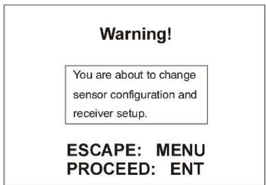
Figure 49 - Sensor config & receiver setup warning window
(CD5308)
2 Press ENT.
©
| SETUP | |||
| PURSE SEINE | NAV | ECHO | SETUP |
| (CD5312) | Speed alarm, units & language | ||
| Interface setup NMEA | |||
| Interface setup remote/alarm | |||
| Sensor alarm/calibration | |||
| Sensor config & receiver setup | |||
| Display colour | |||
| Master reset | |||
Figure 500- DisDisplay colour drop-down menu selected
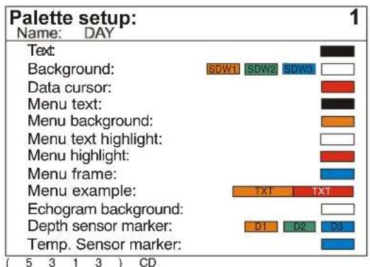
bar
| Category | Value | | -------------------- | ----- | | Text | 1 | | Background | SDW1 | | Data cursor | 1 | | Menu text | 1 | | Menu background | 1 | | Menu text highlight | 1 | | Menu highlight | 1 | | Menu frame | 1 | | Menu example | TXT | | Echogram background | 1 | | Depth sensor marker | D1 | | Temp. Sensor marker | 1 |Figure 51 - Palette setup window
- Palette setup 1: factory settings for daylight operation.
- Palette setup 2: factory settings for night time operation.
2 Press ENT.
- The cursor is now designated by a red box and moved using the Multi-direction button.
3 Move the cursor to the parameter to be changed.
4 Press + or - to change the palette name or colours.
5 Repeat steps 3 and 4 until all desired changes have been made.
6 Press ENT to confirm the changes.
- The Palette setup parameters will not be lost even if the unit is switched off or the power supply disconnected.
7 Press MENU to call up the menu bar and proceed to the next function.
Master reset
1 Press MENU to call up the menu bar.
→ See figure 52.
2 If SETUP is displayed in the top left-hand corner of the LCD press ENT to activate its drop-down menu. If it is not displayed, move the cursor to the SETUP main menu which will automatically activate its drop-down menu.
3 Move the cursor to the Master reset drop-down menu.
4 Press ENT to activate.
→See figure 53.
| SETUP | |||
| PURSE SEINE | NAV | ECHO | SETUP |
| (CD5314) | Speed alarm, units & language | ||
| Interface setup NMEA | |||
| Interface setup remote/alarm | |||
| Sensor alarm/calibration | |||
| Sensor config & receiver setup | |||
| Display colour | |||
| Master reset | |||
Figure 52 - Master reset drop-down menu selected
Reset
Activating the Master reset window will hide the menu bar and display the option to reset the unit.
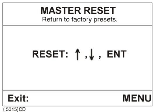
Figure 53 - Master Reset window (See figure 48 for default values.)
1 Press the top of the Multi-direction button.
2 Press the bottom of the Multi-direction button.
3 Press ENT.
- The unit will be returned to factory presets.
4 Press MENU to call up the menu bar and proceed to the next function.
- Speed alarm units & language
- Interface setup NMEA
- Interface setup remote/alarm
- Sensor alarm / calibration
- Sensor config & receiver setup
- Display colour
- Master reset
4 REFERENCE
4.1 Purse seine display references
Overview
Purse seine functions provide continuous monitoring of the fishing operation with regard to the gear and environment. The three available displays from the purse seine drop-down menu are:
- Numeric display
- Graphic display
- Status display
Numeric display with three depth sensor windows
Information concerning up to three depth sensors is horizontally grouped using three different background colours. It is broken down both numerically and symbolically to provide a quick reference for the depth, rise/sink rate and alarm levels of each sensor. By combining this data with the known attachment locations of the sensors to the purse seine, the captain can determine the depth of the net under the surface and if it has, or is about to, stop sinking or begun to rise.

heatmap
| Position | Value | |---|---| | D1 m | 169.5 | | D1 m | 18 | | Data window 1 | Leftward arrow | | D2 m | 146.3 | | D2 m | 01 | | Data window 2 | Leftward arrow | | D2 m | Rightward arrow | | Data window 3 | Leftward arrow | | D3 m | 112.7 | | D3 m | 12 | | Data window 3 | Rightward arrow | | D3 m | Upward arrow (Cp32568) | | D3 m | Downward arrow (Cp32568) | | Cp32568a | Rightward arrow (Cp32568a) | | 5 | Leftward arrow (Cp32568a) | | 6 | Leftward arrow (Cp32568a) | | 7 | Leftward arrow (Cp32568a) | | 8 | Rightward arrow (Cp32568a) |Figure 54 - Numeric display using three depth sensors
1 Senors - Depth sensors are designated by a D1, D2 or D3 and each corresponds to a respective data window. Individual attachment locations to the purse seine must be known so that the displayed numeric information may be properly evaluated.
2 Alarms - Alarm warnings are represented by triangle. Apex up indicates the value is below the alarm level, apex down indicates the value is above the alarm level. Alarm functions are accessed via the Sensor setup alarm/calibration window.
3 D e p t h - Numeric information is calculated and dis in accordance with the units selected. Sensor information is not being received if “*.*” is displayed in place of the depth value. Uncertain readings are indicated by the depth value changing from black to grey.
4 Sensor movement - The black triangular arrow pointing downward indicates the sensor is descending. A black triangular arrow pointing upward indicates the sensor is ascending.
5 Units - Are selected in the Setup for Speed alarm, units and language window.
6 Interference icon- Indicates signal interference due to an other vessel operating in the vicinity. Differently coded signals for individual sensors are available and can be programmed in the field using a PC.
7 Pulse lamp - Signal reception is indicated when the yellow pulse lamp is blinking.
8 Sink rate - Displays the respective sensor's vertical velocity in the selected units per minute.
Note!
Data windows may be displayed in the order which best represents their respective sensors' location on the purse seine. Data window background colours (which aid in the interpretation of displayed data) are selected in Pallet setup. An empty data window signifies that no sensor has been correlated with that particular window.
Numeric display with two depth and one temperature sensor windows
Information concerning up to two depth and one temperature sensors is horizontally grouped using three different data window background colours.
→ Refer to figure 55.
1 Sign - A plus (+) or minus (-) symbol before the value indicates if the ambient water temperature around the sensor is above or below the freezing point for fresh water.
2 Temperature - The ambient water temperature around the sensor.
3 Units - Temperature is displayed in either °C or °F as indicated following the displayed value.

heatmap
| | Value | | ------ | --------- | | D1 m | 169.518 | | D2 m | 146.301 | | T3 | +19.5°C |Figure 555 Nu Numeric display using two depth and one temperature sensor
4 Temperature change - A black triangular arrow pointing downward indicates the water temperature in the vicinity of the sensor is decreasing. A black triangular arrow pointing upward indicates that it is increasing.
Numeric setup
Pressing ENT with the Numeric display open will activate the Numeric setup window.
| Numeric setup: | |
| Data window 1: | Depth 1 - sensor 1 |
| Data window 2: | Depth 2 - sensor 2 |
| Data window 3: | Depth 3 - sensor 3 |
| Show graphic alarm: | ALWAYS |
Figure 56 - Numeric setup window
Variable parameters in the Numeric setup are:
- Data window 1, 2 and 3: Is used to select which sensor is displayed in which data window. This is to help give an overview when several sensors are attached to the purse seine. It is not possible to “remove” sensors and only configurations that agree with regard to senor type are allowed (conflicting combinations will not be registered).
• Show graphic alarm: ON, OFF, ALWAYS
- ON - Displays a graphic alarm when the acoustic alarm is activated.
- OFF - No alarm is displayed.
- ALWAYS - Displays a graphic alarm for values within the selected alarm parameters even if the alarm function is set to OFF in the Sensor alarm/calibration window.
Graphic Display
To differentiate between sensors, information is grouped using the same background colours as the numeric display. The graphic display provides a historic plot of the sinkrate profile of the purse seine.
If an optional echo sounder transducer is installed, the echo sounder display may be superimposed over the graphic display so that data may be compared.
Note ! In this case it is recommended to operate the echo sounder on a frequency of 200kHz to avoid interference with the sensors.
Graphic display information may also be superimposed on an external echo sounder which is capable of reading data in NMEA format.
Depth sensors

line
| Data window | Value | | ----------- | ----- | | D1 | 47.9 | | D2 | 53.2 | | D3 | 51.9 |Figure 57 - Graphic display using three depth sensors
Data windows - Display sensor depth, pulse lamp activity, and sensor identification, they correspond to the data windows used in the numeric display.
1 Main body - Illustrates the sinking profile of the net by means of a depth/time line graph. Individual curves correspond to their respective sensor data windows and are identified by like colours.
2 Time scale - Displayed in minutes on the bottom of the window and is dependent on scroll speed settings.
3 Bar graph - Illustrates the depth of the purse from a "side view" perspective. Individual bars correspond to respective sensor data windows and are identified by colour. The horizontal black hash marks designate the upper and lower selected alarm ranges for each sensor.
4 Depth scale - Display in the scale selected, common for main body and bar graph/alarm range information.
With temperature sensor

line
| Label | Value | |-------|-------| | D1 | 47.9 | | D2 | 53.2 | | T3 °C | 19.5 |Figure 58 - Graphic display using two depth sensors and one temperature sensor
1 Data window - Displays the water temperature in the vicinity of the sensor in either °C or °F and the pulse lamp activity.
2 Temperature scale - Located vertically along the left-hand side of the window.
3 Main body - Illustrates the underwater temperature profile by means of a temperature/depth line graph. The curve corresponds to its respective sensor data window and is identified by colour.
Graphic setup
Pressing ENT with the Graphic display open will activate the Graphic setup window.
| Graphic setup: | |
| Superimpose echo sounder: | NO |
| Scroll speed: | LOW |
| Depth bars: | ON |
| Depth grid: | OFF |
| Temperature marker: | OFF |
| Temperature scale: | OFF |
| Graph line thickness: | 3 |
Figure 59 - Graphic setup window
(CD5267)
Variable parameters in the Graphic setup are:
- Superimpose echo sounder: YES or NO, this menu choice is only valid when an echo sounder transducer is installed and the echo sounder mode is set to NORMAL in the Echo sounder setup.
- Scroll speed: HIGH, MEDIUM, LOW or FREEZE, is controlled by the respective menu choice in the Echo display presentation setup.
•Depth bars: O N or O F F
•Depth grid: O N or O F F
•Temperature marker: O N or O F F
•Temperature scale: O N or O F F
•Graph line thickness: 1 to 5 (pixels)
Status display
The status display provides an overview of PI30 data and insight into the system's performance. This is the first place to look if the system malfunctions.
Information regarding receiver monitoring, digital signal processor (DSP) efficiency and signal to noise ratio (S/N) are conveniently displayed in one main window. Access to such information is a valuable tool in helping to diagnose problems related to the system's hydro- acoustic communications link. The display is designed so that the user can easily interpret and forward critical system information to a shore based technician who can assist in troubleshooting any problems that may arise.

bar
| Ion | Ch 10 (f/kDa) | Ch 16 (f/kDa) | Ch 30 (f/kDa) | |---|---|---|---| | D1 m | 47.9 | - | - | | D2 m | - | - | 53.2 | | D3 m | - | - | 51.9 | | MP Filter: OFF: SW: 0.16 / 0.15 / 0.30 AGC: ON: Hydrophone: CH/R: 16 E: 0 Gain: dB COG: °° D *, * m STW: *. * kn Surface: *. °CFigure 60 - Status display using three depth sensors
• Data windows - Identical to numeric and graphic displays.
• MP Filter - (Multi Path filter) either: ON or OFF.
- SW - Software edition presently installed in the unit.
SW: 0.16 / 0.15 / 0.30 is broken down as follows:
- 0.16 - Display software
- 0.15 - Micro Controller software
- 0.30 - DSP software
• AGC - (Automatic Gain Control) either ON or OFF.
•Hydrophedrene=Indicates=the=cable=condition=and=status=of=the pre-=amplifier=as=follows:
-=Yellow===OK
-=Red===Shortened
-=Dark===Broken=or=no=function
- CH/R -=Transmission=channel=of=the=sensor=presently=being detected.
• E - (Error Message) 0 to 9.
- Frequency spectrum level - A vertical line graph which displays the average signal level of the frequency band, selected by pressing the "+" and "-" buttons.
- Gain - Indicates the level of receiver gain.
- Signal bars - Display received signal information from configured sensors. Each bar is labelled according to the sensor's identification number and present operating channel. Signal=bars=employ=the=same=vertical=scale=as=the=frequency spectrum=level.
When the receiver does not detect a signal, the green bar defects according to its respective frequency spectrum and provides=an=indication=of=relative=background=interference.
When=the=receiver=detects=a=signal,=it=calculates=the=a="noise reference level" with regard to the signal's strength and chosen detection threshold (DT) which adds to the present background noise. The top of the green bar identifies the level a signal must exceed to be detected and the red defection over this=point=represents=the=signal's=relative=strength.
The difference between a signal's strength (top of the red bar) and its associated background noise, measured in the frequency spectrum, provides the signal/noise relationship in decibels.
The=frequency=spectrum=together=with=the=bar=graph provide important=information=on:
- Noise level in the particular frequency band
-=Strength=of=the=sensor's=signal
- Signal/noise relationship for the respective sensor and the margin=available=for=detection
- GPS information - An interfaced GPS provides the status display=with:
-=Vessel's=position.
-=COG===The=vessel's=present=course=over=ground.
- STW = The vessel's speed through the water via an optional triducer.
- Internal clock - Selected using Sensor and receiver setup
- Echo sounder information - If a transducer/triducer is installed:
-=Depth==Water=depth=under=the=vessel.
-=Surface=temperature==Water=temperature=at=the=level=of=the triducer.
4.2 Navigation display references
Overview
Navigation=functions=provide=primary=information=with=regard to=the=vessels=position,=planned=route,=course=and=speed=when=the PI30=is=interfaced=with=a=GPS=navigator.
The two available displays from the Navigation drop-down menu=are:
- Position=display
- Navigation=display
Position display
The PI30 must be interfaced with a (D)GPS navigator, speed log*, and echo sounder (and triducer) to enable the corresponding functions.=The=(D)GPS=navigator=must=be=in=a=navigation=mode such as: Cursor, Waypoint Route or Track.
*Needed=for=speed=through=the=water.
| StatusNo valid POS | Log 10.0nm | Log 20.0nm |
| LAT 56å53.000 NLON 9å50.000 E | ||
| Speed*.* Kn | Course* å | Depth*.*m |
| Water temp.*.* åC | Local time00:00:00 | Local date0-0-0000 |
Figure 61 - Position display
(CD5288)
Position=display=units=are=selected=in=the=SETUP=(main=menu)=and Speed=alarm,=units=&=language=(drop-down=menu)=as=follows:
- Depth:=fathoms,=meters,=feet
- Distance:=nautical=miles,=kilometres,=statue=miles
• Speed: knots, kilometres/hour, miles/hour
• Temperature: Degree Fahrenheit, degree Celsius
Position display information:
Status
The “No valid POS” message indicates that the unit is not presently interfaced with a GPS navigator or there is a fault with the connection or position data. The GPS navigator (master) can experience periods of inadequate satellite reception which results in the interruption of corresponding information to the PI30 (slave).
Log 1
Is a distance log displaying the cumulative distance travelled (over ground) since the log was last reset. Pressing ENT with the Position display window open will activate the Reset log window. Distance is displayed in the unit chosen in the SETUP (main menu) and Speed alarm, units & language (drop-down menu). Selectable values are from 00000.0 to 99999.9.
Log 2
Same as Log 1. Two independent distance logs provide the option of recording the total voyage distance and the distance travelled on individual legs.

Figure 62 - Reset log window
LAT
Latitude in whole degrees and minutes expressed to three decimal places and designated as either N (north) or S (south).
LON
Longitude in whole degrees and minutes expressed to three decimal places and designated as either E (east) or W (west).
Speed
Speed over ground (GPS navigator). Speed through the water (speed log).
Course
The vessel's true or magnetic course steered in whole degrees. Pressing ENT with the Navigation display window open will activate the Navigation setup window where display course and bearing may be selected as either TRUE or MAGNETIC.
Depth
Depth under the keel unless calibrated differently.
Wattentenpp.
Surface water temperature with an interfaced triducer.
Local time
Ship's time selected in the SETUP (main menu) and Sensor config & receiver set (drop-down menu).
Local date
Ship's date selected in the SETUP (main menu) and Sensor config & receiver set (drop-down menu).
Navigation display
The PI30 must be interfaced with a (D)GPS navigator and echo sounder to enable the corresponding functions. The (D)GPS navigator must be in a navigation mode such as: Cursor, Waypoint Route or Track.
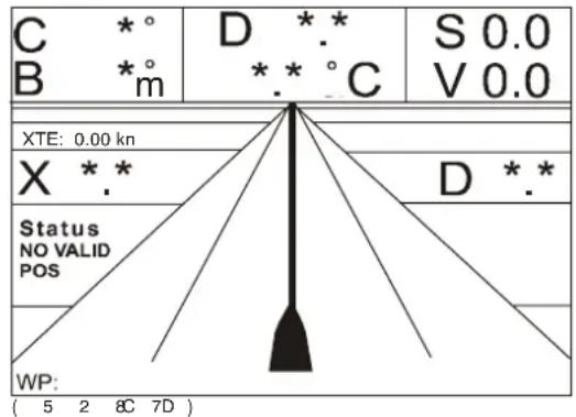
Figure 63 - Navigation display
Navigation display information:
C
Course steered in true or magnetic whole degrees. Pressing ENT with the Navigation display window open will activate the Navigation setup window where display course and bearing may be selected as either TRUE or MAGNETIC.
→ See figure 64.
B
Bearing to next waypoint in true or magnetic whole degrees. Pressing ENT with the Navigation display window open will activate the Navigation setup window where display course and bearing may be selected as either TRUE or MAGNETIC.
D
Depth under the keel unless calibrated differently.
^ C
Surface water temperature with an interfaced triducer.

Figure 644 -
Navigation setup window
S
Speed over the ground.
V
Speed toward a waypoint ("velocity").
XTE
Cross track error alarm distance. Pressing ENT with the Navigation display window open will activate the Navigation setup window where cross track error alarm distance may be selected.
X
Cross track error, the vessel's deviation from the intended track to one decimal place of the selected unit for distance.
D
Distance to the next waypoint to one decimal place of the selected unit for distance.
Status
The "No valid POS" message indicates that the unit is not presently interfaced with a GPS navigator or there is a fault with the connection or position data.
WP
Waypoint or route number.
Navigational display motorway
A three-dimensional representation of the vessel in relation to the intended track and approaching waypoint.
→ See figure 65.
1 Ship's position in relation to the intended track.
2 Approaching waypoint alarm. The interfaced GPS navigator will sound an alarm when the vessel enters this pre-determined circular boundary.
3 The intended course line between two waypoints when the NAV function is activated on the interfaced GPS navigator.

Figure 655 - Navigation display (motorway)
4 Waypoint and waypoint line. The interfaced GPS navigator will sound an alarm when the vessel reaches this point/line.
5 Cross track error (XTE) alarm lines (one on each side of the intended track). The interfaced GPS navigator will sound an alarm should the vessel exceed these pre-determined limits.
4.3 Echo sounder display references
Overview
Echo sounder functions provide primary information with regard to the depth, bottom and targets under the vessel when the PI30 is connected to an optional echo sounder transducer (refer to the Simrad EQ32 operator manual).
The PI30 has two different Echo sounder drop-down menus available. The complete drop-down menu is made up of six choices and the abbreviated version is made up of four. The Turn A-scope ON/OFF and Turn VRM ON/OFF drop down menus do not activate display windows.
The abbreviated Echo sounder drop-down menu is displayed when the unit is turned on for the first time or after being reset using the Master reset function. To replace the abbreviated drop-down menu with the complete version:
The four available displays from the abbreviated Echo sounder drop-down menu are:
- Echo display
- Bottom expansion
•VRN expansion - Echo sounder setup
General
The PI30 must have an optional echo sounder transducer installed to enable the corresponding functions. Specific echo sounder parameters are accessed through the Presentation setup window activated by pressing ENT while the corresponding main function window is displayed. General echo sounder parameters are selected in the ECHO (main menu) and Echo sounder setup (drop-down menu).
Echo display
The basic presentation mode (Echo display window) is primarily used for observing schools of fish and the seabed.
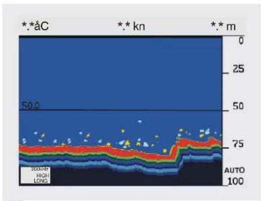
bar_stacked
| Depth (km) | Layer 1 (blue) | Layer 2 (red) | Layer 3 (green) | Layer 4 (yellow) | Layer 5 (light blue) | |------------|----------------|---------------|-----------------|------------------|----------------------| | 0 | 50.0 | - | - | - | - | | 25 | - | - | - | - | - | | 50 | - | - | - | - | - | | 75 | - | - | - | - | - | | 100 | - | - | - | - | - |Figure 66 - Echo sounder basic presentation
Basic display information:
The depth range at the right of the LCD can be adjusted using the - and + keypads or set to AUTO (automatic) via the Presentation setup window.
Upper left-hand corner
Sea surface temperature.
Upper centre
The vessel's speed.
Upper right-hand corner
Present=water=depth.
Across the centre
VRM=-Variable=range=marker=activated=by=pressing=the=VRM keypad=and=positioned=using=the=Multi-direction button.
Lower left-hand corner
Transmitter=status=window=displaying=the=frequency,=transmitter power,=and=transmitter=pulse=length=presently=in=use:
•Selected frequency:=50=or=200kHz
- Transmitter power: HIGH or LOW (proceeded by A=automatic=mode)
- Pulse length: SHORT, MEDIUM or LONG (proceeded by A=automatic=mode)

(CD5325)
Figure 67 - Transmitter status window
Presentation setup window
Pressing ENT with the Echo display window open will activate the=Presentation=setup=window.

Figure 68 - Presentation setup window
Variable parameters in the Presentation setup window are as follows:
- Range start: displayed in the unit for depth chosen in the SETUP=(main=menu)=and=Speed alarm,=units &=language(drop-down=menu).=Selectable Values=are=from=000=to=999.
- Range: incremented in steps according to the unit for depth chosen in the SETUP (main menu) and Speed alarm, units & language (drop-down menu). Range may also be set to AUTO for automatic selection of the depth scale relative to the present maximum=depth.
• Gain may be set up to 99.9 dB.
- Scroll speed: HIGH, MEDIUM, LOW, FREEZE
- White line: O N or O F F
- Expansion window: incremented in steps according to the unit for depth chosen in the SETUP (main menu) and Speed alarm, units & language (drop-down menu).
• TVG: Time varying gain can be set to either: Bottom (20 log R) or Fish (40 log R)
- Sound speed: The speed of sound in water. Only values in meters per second are possible irrespective of the units chosen in the SETUP (main menu) and Speed alarm, units & language (drop-down menu).
• Ping to ping filter: O N or O F F
•Signal threshold: ON or OFF
- Colour threshold: colour choice (box), ON or OFF command. Set as ON to select the colour shown as the level below which other colours will not be shown in the Echo display.
• Depth grid: ON or OFF
•Echo sounder frequency: 200kHz
Refer to the Glossary of terms for more detailed explanations of Presentation setup functions.
Bottom expansion
The bottom lock expansion function provides a reliable depth readout and a compressed standard display in the upper 2/3 of the LCD.
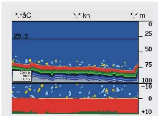
area
| Depth (m) | Value | |-----------|-------| | 0 | 0 | | 25 | 29.3 | | 50 | 75 | | 75 | 100 | | 100 | -10 | | 125 | 0 | | 150 | +10 |Figure 69 - Bottom expansion window
Bottom expansion information:
The depth range at the right of the LCD can be adjusted using the - and + keypads or set to AUTO (automatic) in the Presentation setup window.
Upper left-hand corner
Sea surface temperature.
Upper centre
The=vessel's=speed.
Upper right-hand corner
Present=water=depth.
Horizontal line
VRM=-=Variable=range=marker=activated=by=pressing=the=VRMkeypad=and=positioned=using=the=Multi-direction button.
Lower left-hand side
Transmitter=status=window=displaying=the=frequency,=transmitter power,=and=transmitter=pulse=length=presently=in=use:
•Selected frequency:=50=or=200kHz
- Transmitter power: HIGH or LOW (proceeded by A=automatic=mode)
- Pulse length: SHORT, MEDIUM or LONG (proceeded by A=automatic=mode)
→ See figure 67 on page 52.
Across the top 2/3
Compressed=Echo=display=window.
Across the bottom 1/3
Bottom=expansion=information.
Presentation setup window
Pressing ENT with the Bottom expansion window open will activate=the=Presentation=setup=window.
→ See figure 68 on page 52.
VRM expansion
The VRM expansion function provides an enlarged view of the area=in=the=proximity=of=the=variable=range=marker=(VRM)=to enhance=the=separation=of=echos.
→ See figure 70.
VRM expansion information:
The depth range at the right of the LCD can be adjusted using the - and=+ keypads=or=set=to=AUTO=(automatic)=in=the=Presentation setup=window.
Upper left-hand corner
Sea=surface=temperature.
Upper centre
The=vessel's=speed.

bar_stacked
| Depth (m) | Layer Color | |-----------|-------------| | 0 | Red | | 25 | Green | | 50 | Blue | | 75 | Red | | 100 | Green | | 100 | Blue | | 100 | Dark Blue | | 71 | Red | | 71 | Green | | 71 | Blue | | 71 | Dark Blue | | 70.7 | Red | | 70.7 | Green | | 70.7 | Blue | | 70.7 | Dark Blue |Figure 700 - VRM expansion window
Upper right-hand corner
Present=water=depth.
Horizontal line
VRM=--=Variable=range=marker=activated=by=pressing=the=VRM keypad=and=positioned=using=the=Multi-direction button.
Lower left-hand side
Transmitter=status=window=displaying=the=frequency,=transmitter power,=and=transmitter=pulse=length=presently=in=use:
•Selected frequency:=50=or=200kHz
- Transmitter power: HIGH or LOW (proceeded by A=automatic=mode)
- Pulse length: SHORT, MEDIUM or LONG (proceeded by A=automatic=mode)
→ See figure 67 on page 52.
Across the top 2/3
Compressed=Echo=display=window
Across the bottom 1/3
VRM expansion information, the zoom level can be selected in seven=steps=according=to=the=unit=for=depth=selected=in=the=ECHO(main=menu)=and=Echo=sounder/setup=(drop-down=menu).
Presentation setup window
Pressing ENT with the VRM window open will activate the Presentation=setup=window.
→ See figure 68 on page 52.
A-scope
The A-scope function indicates the precise amplitude or strength of=received=echos=which=may=be=used=in=determining=individual species=of=fish=or=bottom=hardness.

geo
| Depth (m) | Value | |---|---| | 0 | 29.2 | | 25 | 29.2 | | 50 | 29.2 | | 75 | 29.2 | | 100 | 29.2 |Figure 7T1- - A-scope function
A-scope information:
The=depth=range=at=the=right=of=the=LCD=can=be=adjusted=using=the-and=+keypads=or=set=to=AUTO=(automatic)=in=the=Presentation setup=window.
Upper left-hand corner
Sea=surface=temperature.
Upper centre
The=vessel's=speed.
Upper right-hand corner
Present=water=depth.
Right side
A-scope=window.
Horizontal line
VRM=--=Variable=range=marker=activated=by=pressing=the=VRMkeypad=and=positioned=using=the=Multi-direction button.
Vertical line
Event=marker=activated=by=pressing=EVENT on=the=keypad.
Lower left-hand side
Transmitter=status=window=displaying=the=frequency,=transmitter power,=and=transmitter=pulse=length=presently=in=use:
• Selected frequency:=50=or=200kHz
- Transmitter power: HIGH or LOW (proceeded by A=automatic=mode)
- Pulse length: SHORT, MEDIUM or LONG (proceeded by A=automatic=mode)
→ See figure 67 on page 52.
Presentation setup window
Pressing ENT with the VRM window open will activate the Presentation=setup=window.
→ See figure 68 on page 52.
VRM
Is a horizontal black line on the display screen that can be used to measure the distance to targets.

bar_stacked
| Depth (m) | 2004H8 | HIGH | LOW | |-----------|--------|------|-----| | 0 | 0 | 0 | 0 | | 25 | 0 | 0 | 0 | | 50 | 0 | 0 | 0 | | 75 | 0 | 0 | 0 | | 100 | 0 | 0 | 0 |Figure 72 - VRM set at 50.0m
VRM information:
The VRM function may be activated or deactivated by pressing the VRM keypad when either the Echo display or Bottom expansion windows are open.
- The range to the right of the LCD is adjusted using the - and + keypads.
- The VRM is moved vertically using the Multi direction button.
Echo sounder setup
The Echo sounder setup is used to tailor display window functions to the vessel and its operation.
| Echo sounder setup: | |
| Transducer depth below surface: | 0.0 m |
| Keel depth below surface | 0.0 m |
| Display: | DEPTH BELOW SURFACE |
| Alarm for fish: | Strength: 30dB OFF |
| Depth for fish: | min: 10 m max: 100 m |
| Depth alarm maximum: | 100 m OFF |
| Depth alarm minimum: | 10 m OFF |
| Transmitter: | AUTO |
| Transmit pulse length: | AUTO |
| Echo sounder mode: | OFF |
Figure 73 - Echo
sounder setup
window
CD5282)
Echo sounder setup information:
- Transducer depth below surface: displayed in the unit for depth chosen in the SETUP (main menu) and Speed alarm, units & language (drop-down menu). Selectable values are from 00.0 to 99.9.
- Keleldepth below surface: displayed in the unit for depth chosen in the SETUP (main menu) and Speed alarm, units & language (drop-down menu). Selectable values are from 00.0 to 99.9.
- Display: DEPTH BELOW KEEL, DEPTH BELOW SURFACE OR DEPTH BELOW TRANSDUCER
- Alarm for fish: Can be set from 00dB to 30dB and selected as ON or OFF. The minimum setting of 00dB is for weak echos and the maximum of 30dB is for strong echos.
- Depth for fish: displayed in the unit for depth chosen in the SETUP (main menu) and Speed alarm, units & language (drop-down menu). Selectable values are from 0000 to 9999.
- Depth alarm maximum: displayed in the unit for depth chosen in the SETUP (main menu) and Speed alarm, units & language (drop-down menu). Selectable values are from 0000 to 9999 and it may be turned ON or OFF.
- Depth alarm minimum: displayed in the unit for depth selected in the SETUP (main menu) and Speed alarm, units & language (drop-down menu). Selectable values are from 0000 to 9999 and it may be turned ON or OFF.
- Transmitter: can be set as HIGH, LOW, OFF or AUTO (automatic)
- Transmitter pulse length: can be set as LONG, MEDIUM, SHORT or AUTO (automatic).
- Echo sounder mode: can be set as NORMAL, OFF or DEMO.
4.4 PI30 Setup
Overview
Setup functions are used to preset units, user preferences and other variables to tailor the PI30 to individual needs.
The Setup windows are:
•Speed alarm, units & language
- Interface setup NMEA
- Interface setup remote/alarm
- Sensor alarm/calibration
- Sensor config & receiver setup
- Display colour
- Master reset
Speed alarm, units & language
The Speed alarm, units & language setup is used to tailor the PI30 to specific operator preferences and equipment calibrate.
→ See figure 74.
| Setup for speed: | |
| LOG speed sensor: | OFF |
| LOG speed calibration: | 19000 PULSES/nm |
| Speed alarm maximum: | 0.0 kn OFF |
| Speed alarm minimum: | 0.0 kn OFF |
| Setup for units: | |
| Depth in: | METERS |
| Distance in: | NAUTICAL MILES |
| Speed in: | KNOTS |
| Temperature in: | DEGREE CELSIUS |
| Software version: | PI30 0.12 |
| DSP: 0.00. MC: 0.00 | |
| WIN change interval: | 5 sec. MANUAL |
| Display test in: | English GB |
(5300)CD
Figure 744 Set Setup for Speed alarm, units & language window
Speed alarm, units & language information:
•LOG speed sensor: O Nor OFF
-=ON==Speed=through=the=water=from=an=interfaced=speed log.
-=OFF==Speed=over=ground=from=an=interfaced=a=GPS.
- LOG speed calibration:=used=to=calibrate=the=speed=log=by increasing=or=decreasing=the=number/of=pulses=per=nautical mile=from=000000=to=999999.
- Speed alarm maximum: sounds an audible alarm when the displayed=unit=for=speed=chosen=in=the=SETUP=(main=menu) and=Speed=alarm,=units=&=language=(drop-down=menu)=is exceeded. Selectable values are from 000.0 to 999.9 and it may be=turned=ON=or=OFF.
- Speed alarm minimum:=same=as=above,=lower=limit.
- Depth in:=METERS=(m),=FEET=(ft)=or=FATHOMS=(fm).=The Italian=language=uses=BRAT.
- Distance in:=KILOMETRES=(km),=STATUTE=MILES=(mi)=or NAUTICAL=MILES=(nm)
- Speed in: KILOMETRES / HOUR (kh), MILES / HOUR (mh) or KNOTS=(kn)
• Temperature in: DEGREE CELSIUS or DEGREE FAHRENHEIT
- Software version:=Is=not=a=selectable=variable,=but=identifies which=software=version=is=installed=in=the=unit.
- WIN change interval: the factory program default is five seconds which may be changed as necessary up to 99 seconds. This=function=may=be=set=to=MANUAL—or=AUTO:
- MANUAL = The four selected display windows are changed by pressing the WIN keypad.
-=AUTO==The=four=selected=display=windows=are=changed automatically according to the interval selected. The AUTO function may also be activated by pressing the WIN keypad for about two seconds and deactivated by pressing WIN to return to=manual operation.
- Display text in: the unit is supplied with the national language of=the=country=in=which=it=was=purchased=and=English.=The system=is=available=in=the=following=languages:
$$ \text { English(GB) } = \text { French(F) } $$
$$ \text { English } = (\mathrm{USA}) = \text { Spanish } = (\mathrm{E}) $$
$$ \text { Danish } = (\mathrm{DK}) \quad \text { NETHERLANDS } = (\mathrm{NL}) $$
$$ \text { Swedish } = (\mathrm{S}) \quad \text { Italian } = (\mathrm{I}) $$
$$ \text { German } = (\mathrm{D}) \quad \text { Portuguese } = (\mathrm{P}) $$
$$ \text { Norwegian } = (N) $$
Interface setup and NMEA connector
The=interface=setup=NMEA=for=the=connector=is=used=to=coordinate the input of information into the PI30 from external sources. NMEA0183 is compatible with most instruments including the DE30=Dual station.
| Interface setup NMEA: | ||
| Input pin (3,4): | NMEA0183 | |
| Position: | GLL ON | |
| Course: | VTG ON | |
| Speed: | VTG ON | |
| Navigation (APB, RMB and XTE): | ON | |
| Water temperature: | MTW ON | |
| Output pin (1,2): | NMEA0183 | |
| DBK ON | DBS OFF | DBT OFF |
| DPT ON | MTW ON | VHW ON |
| Output pin (1,2): DATA FROM DSP | ||
| Configuration (PSIMP,C): | ON | |
| Data (PSIMP,D): | ON | |
| Sensor definition (PSIMP,F): | ON | |
| Frequency spectrum (PSIMP,S): | ON | |
| Transit (PSIMP,T): | ON | |
C 5302
Figure 75 - Interface setup NMEA window
Interface setup NMEA information:
- Input pin (3,4): NMEA0183, normally interfaced with the (D)GPS=receiver.
- Position: can be set as ON or OFF with regard to the following selectable codes:
- GLL = Geographic position, latitude/longitude
- RMA = Recommended minimum specific Loran C data
- RMC = Recommended minimum specific GPS data
- GGA==Global=positioning=system=fix=data
- VTG = Track made good (course) and ground speed
•Course: same as above
•Speed: same as above
- Navigation (APB, RMB and XTE): can be selected as ON or OFF.=The=codes=are=not=selectable:
-=APB===Autopilot=sentence="B"
-=RMB===Recommended=minimum=navigation=information - = XTE = Crosstrackerror, measured
•Water temperature:=MTW=ON=or=OFF - DBK:=Depth=below=keel=ON=or=OFF
- DBS:=Depth=below=surface=ON=or=OFF
- DBT:=Depth=below=transducer=ON=or=OFF
•DPT:=Depth=including=offset=ON=or=OFF - MTW:=Water=temperature=ON=or=OFF
•VHW:=Water=speed=heading=ON=or=OFF - Configuration (PSIMP,C): O N or O F F
•Data (PSIMP,D): O N or O F F - Sensor definition (PSIMP,F): O N or O F F
• Frequency spectrum (PSIMP,S):=ON=or=OFF
•Transit (PSIMP,T): O N or O F F
Interface setup remote/alarm
The=interface=setup=remote/alarm=is=used=to=control=the=remote and alarm information relayed by the PI30. NMEA0183 is compatible=with=most=instruments=including=the=DE30 Dual station.
| Interface setup remote/alarm: | |
| Input pin (3,4): | NMEA0183 |
| Position: | GLL OFF |
| Course: | VTG OFF |
| Speed: | VTG OFF |
| Navigation (APB, RMB and XTE): | OFF |
| Water temperature: | MTW OFF |
| Interface setup alarm: | |
| Output pin (5,2): | ALARM ON |
| Alarm stand-by level: | LOW |
CD5305)
Figure 76 - Interface setup remote/alarm window
Interface setup NMEA information:
- Position: can be set as ON or OFF with regard to the following selectable=codes:
-=GLL==Geographic=position,=latitude/longitude
-=RMA==Recommended=minimum=specific=Loran=C=data
-=RMC===Recommended=minimum=specific=GPS=data
-=GGA===Global=positioning=system=fix=data
- VTG = Track made good (course) and ground speed
• Courses: same as above
•Speed: same as above
- Navigation (APB, RMB and XTE): can be selected as ON or OFF.=The=codes=are=not=selectable:
$$ - = \mathrm{APB} = = = \text { Autopilot } = \text { sentence } = " B" $$
$$ - = \mathrm{RMB} = = = \text { Recommended } = \text { minimum } = \text { navigation } = \text { information } $$
$$ - = X T E = C r o s s t r a c k e r r o r, m e a s u r e d $$
•Water temperature:=MTW=ON=or=OFF
- Output pin (5,2):=ALARM=is=either=ON=or=OFF
•Alarm stand-by level: H I G H o r L O W
Sensor alarm/calibration
Controls the minimum and maximum alarm depths and calibration of the sensors. Alarm can be generated to produce both=graphic=and=audible=signals.
Note!
Graphic alarms, selected using the Numeric setup, can be displayed even if the audible alarm parameter in Alarm setup is selected as OFF.
Depth sensors are supplied calibrated from Simrad. The one meter=reference=level=may=be=adjusted=by=(+)or=(-)=9.9=meters.
Alarm setup:
Depth 1: min: 0 m OFF. Max: 300 m OFF
Depth 2: min: 0 m OFF. Max: 300 m OFF
Depth 3: min: 0 m OFF. Max: 300 m OFF
Depth sensor:
| Calibration: | NO | ||
| Offset: | D1:0.0 m | D2:0.0 m | D3:0.0 m |
Figure 77 -
Sensor
alarm/calibration
window
(CD5310)
Sensor alarm
- Depth 1: minimum depth; ON or OFF and maximum depth ON=or=OFF=alarm=depths.
•Depth 2:=Same=as=above. - Depth 3:=Same=as=above.
•Calibration: Yes or NO - Offset: Calculated during the calibration process or set manually.
Sensor calibration
→ Refer to the section on Setup for sensor alarm/calibration on page 33.
Sensor configuration & receiver setup
Configures the PS30 sensors according to task and channel and sets purse seine parameters.
Note ! After activating Master Reset and when the display and control cabinet is first delivered from the factory, sensor configuration will selected as NONE and channel selections to NO.
| Sensor configuration: | |||
| Sensor 1: | DEPTH - Channel: | 2 | |
| Sensor 2: | DEPTH - Channel: | 12 | |
| Sensor 3: | DEPTH - Channel: | 22 | |
| Status & receiver: | |||
| Hydr. audio: | OFF | Volume: | 5 |
| AGC: | ON | Manual gain: | 0 dB |
| MP filter: | OFF | MPF level: | 42 dB |
| Miscellaneous: | |||
| Max shooting speed: | 5 kn | ||
| Detection threshold (DT): | 8 dB | ||
| Sensor filter: | OFF | ||
| Time: | 0:00:00 | Date: | 00-0-0000 |
Figure 78 - Sensor config & receiver window
Sensor configuration & receiver setup information:
- Sensor 1: Set to either DEPTH, TEMPERATURE or NONE and Channels 1 to 30 or NO.
- Sensor 2: Same as above.
- Sensor 3: Same as above.
• Hydr. audio: Not implemented.
• Volume: Not implemented.
- AGC: Automatic Gain Control, the default setting is ON and is controlled manually in steps of 0, 20 and 40 decibels when set to OFF.
- Manual gain - When AGC is set to ON this setting has no effect. Manual gain is useful when working at maximum detection ranges with favourable noise levels. The default setting is 0 decibels. Refer to the section discussing the status display for more information.
- MP filter / MPF level: The Multi Path filter default setting is OFF and the Multi Path level default setting is 42dB. When the Multi Path filter is set to OFF, the Multi Path level is not of consequence.
Operating in an areas with substantial reverberation due to bottom topography or in shallow waters can cause problems when consecutive operating channels have been configured, but the corresponding sensors are not in use. False signals and sporadic error values can also be caused by other types of hydro acoustical equipment operating on PI30 frequency range.
The MP filter should be set to ON when interference is experienced. If this does not help, adjust the MPF level in small steps to correct the situation (lower values represent stronger filtering). It is best to experiment with this parameter by reducing the value in steps of 3dB until the detection error disappears. Check that the signals from the sensor in use are still being received, if they are not, the MP filter will not be of help in this particular situation. The MP filter's effectiveness is both location and net specific. Therefore, the same parameters will not necessary work in different areas or using various types of nets.
• Max shooting speed: From 0 to 20 knots.
The PI30 has a built in Doppler compensation function which is configured using the Max shooting speed (the default value is five knots). This parameter and related function is only relevant if sensor data is desired while the purse seine is being deployed and has no effect once the vessel is stopped, waiting for the net to sink. Be aware that setting the Max shooting speed parameter too high can create a conflict with the channel selection (Refer to the section on Setup for sensor alarm/calibration on page 33). Should this situation arise, the message "Max shooting speed differs from wanted, channels are set too close to each other" will be displayed.
- Detection Threshold (DT): Has a default value of 8dB. If there is a problem with interference signals generating false data and all of the configured sensors are operative (analogous with the Multi Path problem); increase the value carefully in steps of 1dB.
High DT values allow only strong sensor signals to be detected. A lower DT value will provide greater range if conditions are optimal, but if too low, interference will be detected. It is best to experiment with different values to determine which to employ.
Note!
If the Detection Threshold (DT) value is set higher than 28dB, all signals will be prevented from being detected.
- Sensor filter: OFF (default), LIGHT or HEAVY. When the Sensor filter is set to OFF, no filtering takes place. Light filtering averages the data received by the last four pings. Heavy filtering averages the data received by the last eight pings and is only recommended if there are large fluctuations in the displayed data, or the rate of change is small. Reduced filtering shortens the delay between updating the changes in sensor location and the corresponding displayed information.
The HP30 is designed to quickly update data. After the sensors have been submerged, the receiver requires only three consecutive pings from individual sensors to calculate and display their respective information. Should one or two pings be lost, the predicted value is displayed in grey text (uncertain reading). If all three pings where not received, the value is displayed as *.*
•Time: Present time
•Date: Present date
Sensor configuration & receiver parameters
Sensor configuration
Sensors can be configured in any combination. For example, sensor 1, 2 or 3 can be configured as depths 1, 2 or 3 representing the 1/4, 2/4 (1/2) and 3/4 sections of the purse seine, or as two depth sensors and one temperature sensor. What ever configuration is selected, the attachment locations of the sensors must be noted so that the received data may be properly interpreted.
Channel selection
Each sensor must be clearly marked before hand with its configured channel number (from 1 to 30).
→ Refer to figure 90 on page 83
These individual coded signals should be carefully chosen to avoid interference from other vessels operating in the vicinity. The selected operating channels for the individual sensors should be noted in the Sensor calibration table (table 1 on page 34).
Optimally, selected channels should be separated as much as possible to increase Doppler tolerance. The PI30's internal computer protects against incompatible channel selection due to Doppler tolerance conflicts and is controlled by the parameter Max shooting speed. Should two consecutive channels be chosen, Max shooting speed may be set to no more than six knots.
Display colour
The LCD colours may be customized as desired. There are nine different display settings for all objects and text shown on the screen.
→ See figure 79.
Display colour information:
- Palette setup: (number from 1 to 9) refers to the preset pallets - Palette setup 1: factory settings for daylight operation.

bar
| Category | Value | | -------------------- | ----- | | Text | Black | | Background | SDW1 | | Data cursor | Red | | Menu text | Black | | Menu background | Orange| | Menu text highlight | White | | Menu highlight | Red | | Menu frame | Blue | | Menu example | Red | | Echogram background | White | | Depth sensor marker | D1 | | Temp. Sensor marker | Blue |Figure 799 - Palette setup window
-=Palette=setup=2:=factory=settings=for=night=time=operation.
- Name: identifies a specific pallet by name, up to 31 characters may=be=used
-=DAY:=factory=settings=for=daylight=operation.
-=NIGHT:=factory=settings=for=night=time=operation.
- Text:=16=different=colours=to=chose=from
- Background: 16 different colours to chose from for the following:
-=Main=background=for=all=windows
-=SDW1===Purse=seine=senor=1=information=background
- SDW2= = Purse= seine= senor= 2= information= background
--SDW3===Purse=seine=senor=3=information=background
- Menu text:=16=different=colours=to=chose=from
- Menu background:=16=different=colours=to=chose=from
- Menu text highlight: 16 different colours to chose from
- Menu highlight:=16=different=colours=to=chose=from
- Menu frame:=16=different=colours=to=chose=from
- Menu example: provides a preview of the present palette selection
- Echogram background:=16=different=colours=to=chose=from
- Depth sensor marker: 16 different colours to chose from for the following:
-=D1===Purse=seine=senor=1=marker
-= D2= = Purse= seine= senor= 2= marker
-=D3===Purse=seine=senor=3=marker
•Temp. sensor marker:=16=different=colours=to=chose=from
5 TROUBBLESHOOTING
5.1 General PI30 information
Warning! Do not operate the display and control unit without the protection provided by the 2A fuse. Use of any other rated fuse may cause severe damage to the unit
5.2 PI30 Display and control cabinet
No picture on the LCD
1 Has the unit been switched on?
- Press PWR on the keypad.
2 Has the fuse blown?
- Check the 2 A power cable fuse. Replace if required.
- Press PWR on the keypad.
3 Are all the system's cables connected firmly?
- Remove and replace cable connections checking contact surfaces for corrosion or damage.
LCD picture is too dark / bright
1 Is the background colour appropriate with regard to the ambient lighting,?
- Change the background colour setting: to white for daytime use and for black for nighttime.
- Adjust the LCD light / contrast by pressing PWR and then MENU on the keypad.
Abnormal LCD picture
1 Is LCD presentation faulted or degraded?
- Turn the unit OFF and ON again by pressing PWR on the keypad.
Echo sounding picture appears normal, but no targets or only noise is displayed
1 Is the system's hydprohone cable connected firmly to the display and control unit?
- Remove and replace the cable checking contact surfaces for corrosion or damage.
2 Is the receiver gain set high enough?
- Increase the receiver gain as describe in the echo sounder menu section, presentation setup.
3 Is the range set correctly with regard to water depth?
- Adjust the range as describe in the echo sounder menu section, presentation setup.
4 Is the Demo mode activated?
- Set Demo to OFF in the echo sounder setup menu.
No response to keypad input
1 Does manual input via pressing buttons on the keypad yield no response from the unit?
- Disconnect and connect power to the unit.
No normal picture or keypad input
1 Does the unit not respond to keypad input or displays an abnormal picture?
- Perform Master reset described in thesection on
It is not possible to choose between 50kHz and 200kHz in the echo sounder setup
1 Is the Demo mode activated?
- Set Demo to OFF in the echo sounder setup menu.
6 MAINTENANCE AND REPAIR
6.1 General
Service
The PI30 Purse seine system does not contain any operator serviceable parts. Opening individual components will void their respective warranties and touching internal electrical parts may cause bodily harm. Consult the section on troubleshooting if the system is not working properly or contact your authorized Simrad dealer for service and repair.
Spare parts
Fuses (2AF) may be purchased from a chandlery or a marine supply store. If you require a Simrad part, please contact your authorized dealer.
6.2 PI30 Display and control cabinet
Surface cleaning
Wipe the cabinet and LCD with a clean cloth moistened with fresh water. For heavier cleaning, dip the cloth in a solution of mild dish soap and water. Be sure to avoid excessive moister or cleaning solutions that contain alcohol or petroleum products.
Electrical connections
Periodically check the electrical connections for corrosion. Make sure that all connections are tight and that cables are not frayed or worn.
6.3 PS30 Hydrophone
Cleaning
Periodically clean the face of the hydrophone with a plastic utensil using a scrubbing action. Do not use harsh abrasive or solvents.
Dry dock
Protect the hydrophone face from sand/water-blasting and painting.
6.4 PSS00 portable hydrophone
Cleaning
The portable hydrophone and cable should be cleaned with fresh water after use. Keep the plug at the end of the cable as dry as possible and avoid it from being immersed in water.
Storage
The hydrophone and cable should not be left on deck when not in use and stored on the supplied reel with the following general precautions:
•The cable does not chafe due to motion of the vessel.
- Avoid sharp edges that could damage the hydrophone cable insulation.
- Do not knot or kinked the cable.
6.5 PS30 Depth and temperature sensors
Cleaning
Sensors and related mounting hardware should be cleaned with fresh water after use and before storage.
Note ! The sensors are designed to turn themselves on automatically when week current passes from the cover to the fastening lugs. A film of residual sa on the surface of a sensor can conduct enough electricity to automatically energise the the unit and inadvertently drain the battery.
Extra protection
To protect against the build-up of salt, cover the surface of the unit and its cover with a thin layer of silicon grease.
7 BATTERY CHARGING AND TESTING
7.1 Charging PS30 sensors
General
PS30 depth and temperature sensors are charged in the same manner, each with its respective charger. Three different Simrad sensor chargers are available depending on the vessel's main power supply:
• 220 VAC - Simrad sensor charger (reg. nr. 107-073189).
• 110 VAC - Simrad sensor charger (reg. nr. 107-073190).
• 24 VDC - Simrad sensor charger (reg. nr. 107-204060).

natural_image
Sensor charger with coiled cable and two clampers on a wooden surface (no text or symbols visible on main subject)Figure 80 - Sensor charger
WARNING!
The use of chargers or procedures not specified in these instructions is forbidden. Incorrect charging of PS30 depth/temperature sensors can result in material damage or personal injury due to fire or explosion.
When to charge the sensors
The PS30 depth/temperature sensors' internal batteries are charged (normal charge) with a constant current of 50 mA. This allows the chargers to remain connected to the sensors for extended periods of time with no danger of overcharging.
PS30 sensors should be charged:
• After 30 hours of consecutive use.
- Not in use / storage.
7.2 Charging procedure
The following procedure will insure maximum battery life and optimal system performance:
1 Clean the tRS30S sensor in fresh water to remove salt.
2 Secure the PS30 sensor against the motion of the vessel. Ensure that the fastening lugs do not come in contact with conductive material. Completing the circuit between a negative and positive fastening lug will prevent charging.

Figure 81 - PS30 depth/temperature sensor
3 Attach the Sensor charger's red alligator clamp to one of the PS30 sensor's fastening lugs designated with a plus (+) symbol.
4 Attach the Sensor charger's black alligator clamp to one of the PS30 sensor's fastening lugs designated with a minus (-) symbol.
Note!
Check that there is direct metal-to-metal contact between the alligator clamps and fastening lugs. Objects such as wet rope separating the two metal surfaces or shorting of the positive and negative terminals may cause electrolysis with the possibility of severely damaging or creating a short between the fastening lugs.
5 Check that the red light on the Sensor charger is illuminated confirming that the alligator clamps are connected correctly.
If the battery is completely dead, the red light on the Sensor charger many not illuminate. Should this be the case, clean the sensor in fresh water and resume charging. Once the battery voltage begins to increase, the red light on the Sensor charger will illuminate and the sensor should then be charged for a minimum of 14 to 16 hours.
Note!
The red light will illuminate even if an object capable of conducting electricity, such as wet rope, is trapped between an alligator clamp and fastening lug.
6 Check that the PS30 sensor's internal light blinks every four seconds confirming that it is charging.
7 Charge sensors with flat batteries a minimum of 14 to 16 hours.
Note!
Never charge PS30 depth/temperature sensors at a temperature of lower than 0 ^ ( 32 ^ ).
7.3 Testing
Normal condition
Touch the test point (bare metal tab) on the depth cover and a fastening lug at the same time. This will cause the sensor to identify the channel it transmits on with a series of blinks and begin sending data if it is not programmed differently.
→See figure 90 on page 83.
Depleted battery
If the sensor does not blink, it should be charge for a few minutes and tested again. If it then blinks and begins to send data, it should be charged for at least 16 hours. If the sensor continues to just blink, charge it a little longer and then test it again.
Possible fault
If a charged sensor blinks its identification code every four seconds, there is a fault with the depth cover. Contact your nearest Simrad dealer.
8 SYSTEM INSTALLATION
8.1 General
Planning
Installation of the PI30 should be carefully planned keeping in mind that the supplied cable for connecting the display and control unit to the hydrophone is ten meters long.
Cable
Running the hydrophone cable through a grounded conduit greatly decreases the likelihood of interference. To further reduce the chance of poor system performance, the hydrophone cable should be installed away from other electrical cables or sources. If it is necessary to pass close to other cables, it is best to keep as much distance from them as possible and make all crossings at right angles.
Sealed system
The PI30 display and control unit, depth / temperature sensors and hydrophone are all factory sealed and do not contain any user serviceable parts. Opening the the system's components is unnecessary for installation and doing so will void their respective warranties.
Grounding
The PI30 is a sophisticated piece of electronic equipment. To reduce electrical interference and risk of electrical shock, properly ground the system using the designated terminal on the back of the display and control unit.
→ Note the location of the ground screw in figure 82.
Power source, fuse and power cable
Ensure that the DC power supplied to the PI30 is within the range of 10 to 32V. Note that only a 2 A fuse may be employed and that the power cable is firmly attached.
8.2 PI30 display and control unit
Mounting
The PI30 display and control unit's compact design and installation flexibility allow it to be flat, bracket, overhead, bulkhead or console mounted.

Figure 882- BacBack of PI30 cabinet
Bracket mounting
The display and control unit may be securely mounted on any flat surface using the supplied bracket. The unit is tilted as required by loosening and tightening the integrated pivot wheels on each side of the cabinet.
→See figure 83.
Bracket mounted
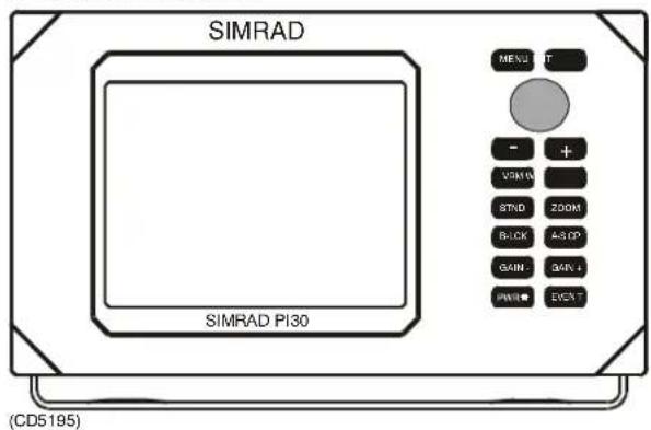
Figure 83 - Bracket mounted PI30
Mounting options
Bracket mounting of the PI30 is less complicated than flush mounting and affords greater flexibility with regard to screen orientation. Problems involving glare, background lighting or obstructed viability of the LCD may not be realised until after installation. In such cases the unit may be both tilted in the horizontal plan using the pivot wheels or the bracket re-mounted to change the aspect in the horizontal plane.

Figure 884 MoMounting options for the PI30
Flush mounting
The PI30 may be counter-sunk into any flat surface using the four screw holes hidden under the removable corners. Refer to the cut-out template for specific instructions.
→See figure 85.
8.3 Electrical connections
General
All of the PI30 system's cable connections are located at the back of the display and control unit. The hydrophone wire must be spliced as necessary.
→ See figure 106 on page 104.
Power supply connections
Cable
The internal voltage regulator allows the PI30 to operate normally with power supply fluctuations ranging from 10 to 32Vdc. The display and control cabinet is connected to the external power supply by the supplied 1.5m power cable.
Once the supplied cable is connected to the power source, push the plug as far as it will go into the two pin receptacle labelled PWR on the back of the PI30 cabinet. Turn the plug's coupling ring clockwise until it "clicks" into the locked position.
Fuse
Use the supplied 2AF fuse or a specified replacement. Jumping the circuit or using a non-specified fuse, even for a short period of time, may result in irreparable damage to the equipment.

Figure 85 - Flush mounted PI30
Hydrophone connection
Cable
The PI30 is connected to the hydrophone by the supplied 22 meter cable. The cable's female plug is pushed as far as it will go into the receptacle labelled ANT on the back of the display and control cabinet. Turn the plug's coupling ring clockwise until it "clicks" into the locked position. The PI30 must be turned off when connecting or disconnecting the hydrophone cable.
Note!
Do not plug the hydrophone's female plug into the receptacle labelled ECHO on the back of the display and control cabinet. This could damage the hydrophone by subjecting it to voltage higher than it was designed for.
NMEA 0183 interface connections
Cable
NMEA 0183 interface connections are made using the receptacle labelled NMEA on the back of the display and control cabinet. Turn the plug's coupling ring clockwise until it "clicks" into the locked position. The PI30 must be turned off when connecting or disconnecting the NMEA 0183 interface connections.
Sensor configuration
See the section on PI30 Setup on page 58.
9 SENSOR CONFIGURATION
General
Sensors are delivered from the factory configured with common default settings. Individual sensors may be re-programmed with regard to:
•30 different transmission channels
- LED control
- Ping control
- LED flash at start up
Sensor configuration normally takes place on shore and is performed by an authorised Simrad dealer. It may also be at sea as only a PC and the correct software is required.
The wide range of available channels allows several vessels using PI30 systems simultaneously to operate in the same area without interference.
Necessary equipment
The following is required for PC/sensor interface:
- PS30 Sensor Configuration Software (Simrad reg. nr. 889-204037)
• A PC capable of running the configuration software
• A programming cable (Simrad reg. nr. 380-201154)
•A gender adapter for the programming cable
9.1 Programming
PS30 Sensor Configuration Software
The configuration of sensors is performed using a PC equipped with a mouse or similar device. Click or drag on the sensor configuration window's corresponding boxes to change parameters or execute commands.
Sensor configuration window functions:
1 Establish Communications with Sensor - Click to initiate sensor interface.
2 Read Sensor data - Click to down-load pre-programmed sensor information.
3 Select Sensor Communication Channel - Click to enter channel number.

Figure 886- SenSensor configuration window
4 Program Sensor - Click to enter new parameters.
5 Terminate Communication - Click to stop program interface.
6 Dialogue box - Displays program status and information.
7 Drop-down menu - Click to view menu choices, click the respective menu text to execute the corresponding window related function.
Figure 87 - Drop-down menu
8 Title box - Displays software version and date.
9 Channel number - Click the respective arrow to select channels 1 to 30.
10 LED Control - Drag the vertical bar to select:
Startup Only - The internal LED will only illuminate (flashing the identification code) when the sensor is energized.
Only when Pingging - The internal LED will only illuminate when the sensor pings (transmits data).
When <2m - The internal LED will only illuminate when the sensorisatadepthoflessthan2 meters.
Always - The internal LED will always illuminate as programmed.
11 Window functions - Click to:
A - Hide the window
B - Fill the whole screen with the window
C - Close the window (and exit the program)
12 Ping control - Drag the vertical bar to select:
Always - The sensor pings continually as programmed. Depth>2m - The sensor only pings when at a depth of greater than two meters.
13 Set factory default - Click to configure sensor with the original factory default settings:
Select Sensor Communication Channel - 16
LED control - Startup only
Ping control - Always Show channel with LED flash at start up - Yes
14 Help - This function is not presently available.
15 Communications Port Setup - Click to open dialogue box.

Figure 88 - Com Port Setup dialogue box
COM Port Setup - Used to select which communication port the programming cable (gender adapter if necessary) is plugged into the back of the computer. Slide the vertical bar tho select either COM1 or COM2 and click the OK box to enter the desired port.
16 Beep - Turns the audible "beep" On and Off using the corresponding vertical bar. The yellow pulse lamp is illuminated in unison with beeping.
17 Quit - Terminates and exits the program.
18 Show channel with LED flash at start up - activates or deactivates the channel LED identification flash by selecting Yes or No using the corresponding vertical bar.
Channel 16 LED flash identification code

Figure 889-LED flashshunehandellificidentification example
19 Sensor type - This function is not presently available.
Connecting the PS30 sensor
To interface the sensor with the PC:
1 Attach the gender adapter (if required) to the end of the programming cable.
2 Plug the programming cable (gender adapter) into one of the COM ports on the back of the PC.
3 Attach the programming cable's red (positive) alligator clip to one of the PS30 fastening lugs designated with a plus symbol (+).
4 Attach the programming cable's black (negative) alligator clip to one of the PS30 fastening lugs designated with a minus symbol (-).
→ Refer to figure 81 on page 72.
Changing sensor configuration
To re-program a sensor:
Note!
The internal LED illuminates once a second while the sensor is being programmed. Recommended settings are those used in the factor default configuration.
1 Connect the sensor to the PC using the programming cable.
2 Start the PS30 Sensor Configuration Software.
Once the sensor establishes communication with the PC it is "woken up" and will illuminate (flashing for two second intervals with two second pauses).
3 Click Communications Port setup.
The Com Port Setup dialogue box is displayed.
4 Select COM1 (recommended) or COM2 and click OK.
5 Click Establish Communications with Sensor, the Dialogue box displays:
Waking up sensor...
Requesting data from sensor...
Sent: \$PS30,*2C
Echo: \$PS30,*2C
Rcvd: \$PS30,XX,0.2,D,08*67 (XX = 16 default)
Comp. chksum:67
Rcvd. chksum:67
Senor in channel XX (XX = 16 default)
6 Click Select Sensor Communication channel.
7 Repeatedly click the appropriate arrow in the Channel number box until XX (desired channel) is displayed.
8 Click LED Control and drag the vertical bar to Startup Only (recommended), Only when Pinging, When <2m or Always.
9 Click Ping control and drag the vertical bar to Always (recommended) or Depth>2m.
10 Click Show cannel with LED flash at start up and drag the vertical bar to Yes (recommended) or No.
11 Click Program Sensor, the Dialogue box displays:
Waking up sensor...
Requesting data from sensor...
Sent: \$PS30,*2C
Echo: \$PS30,*2C
Rcvd: \$PS30,XX,0.2,D,08*67 (XX = 16 default)
Comp. chksum:67
Rcvd. chksum:67
Senor in channel XX (XX = 16 default)
Transmitting Programming Command
Sent: \$PS30,XX,D,08*61 (XX = selected channel)
Echo: \$PS30,XX,D,08*61 (XX = selected channel)
Rcvd:\$PS30,XX,0.2,D,08*61 (XX = selected channel)
Comp. chksum:61
Rcvd. chksum:61
Senor in channel XX (XX = selected channel)
Success!
12 The sensors have now been successfully configured with the new parameters. They will no longer flash confirming that programming is finished and communication with the PC has been terminated.
13 Test that the sensors have been properly configured by placing the thumb and forefinger of your left hand on the sensor label test point and lower, negative (-) fastening lug respectively. The sensor will respond by flashing the correct LED identification code. Should the sensor not respond try wetting your fingers or completing the circuit with a small piece of wire.
14 Using waterproof pen, write the channel number and sensor identification on each of the respective sensor labels. Note this same information on table 2 on page 36.

Figure 90 - Sensor label
1 Test point, place thumb here when testing.
2 Write sensor identification here.
3 Write channel number here.
9.2 Self-made programming cable
Required parts
Should a Simrad programming cable not be available, it is possible to make an adequate substitution using the following:
• A 9-pin, Sub-D female connector
• Approximately one to two meters of 2- wire cable
• A 3 kohm resistor
- Two alligator clamps
Assembly procedure
The cable assembly procedure is as follows:
1 Connect pin number two of the 9-pin, Sub-D female connector to one end of the (+) lead of the 2- wire cable. At the other end of the (+) lead, connect the positive (red) alligator clamp.
2 Connect pin number five of the 9-pin, Sub-D female connector to one end of the (-) lead of the 2- wire cable. At the other end of the (-), connect the negative (black) alligator clamp.
3 Conceir the the sistor between pins number two and three of the 9-pin, Sub-D female connector.
4 Check both alligator clamps and respective pins for continuity.
10 DEPTH SENSOR ATTACHMENT
General
The correct attachment of depth sensors to the purse seine is vital to system performance and safety of the units. It is therefore highly recommended that the supplied stainless steel karabiners (two per sensor, Simrad reg. nr 099-204046), or their equivalent, be used. Also available as optional equipment through your Simrad dealer are the various wire and rubber straps described in the following chapter.
Coverage
A PS30 sensor transmit information in the form of sound waves from within its hemispherical top. This conically shaped transmission beam covers a sector of approximately 70^ from the vertical axis of the unit providing communication with the hydrophone even when not optimally oriented.

natural_image
Line drawing of a symmetrical abstract shape with curved lines and labeled 'SIMRAD' (no text or symbols beyond the label)Figure 91 - PS30 transmission beam
Attachment
It is very difficult to control the orientation of sensors attached to a purse seine. They should normally be allowed to hang as freely as possible so that the centre of their beams are directed vertically providing symmetrical coverage on the surface. Special arrangements, or sensors attached differently than described in these instructions, must ensure that their beams are directed toward the hydrophone when pursuing.
The type of fishing operation provides the basis for which mounting arrangement should be used. Due to the fact that vessels, procedures, nets and related gear vary widely, it is not feasible to consider all possible alternatives and provide a method for each that will work.
The following information describes various scenarios for several common fishing operations. These instructions are to be used as a guide and sensor mounting should be tailored to suit individual needs as performance and experience dictate.
Attaching depth sensors to the purse line
Sensors are attached to a purse line using a purse ring, through which is passed a wire strop with two karabiners at either end made fast to the unit's topmost fastening lugs. This attachment method is only recommended when the purse rings are hung and deployed outboard of the bulwarks.
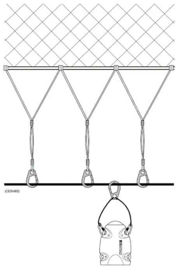
natural_image
Diagram of a rope harness with hanging weights and a hanging weight labeled (CD5493), no text or symbols present.Figure 92 - Purse line attachment
The benefits of attaching sensors to the purse line are they:
- Are located outboard of the bulwarks when shooting and are deployed directly into the sea avoiding contact with the vessel.
- Hang vertical when deployed and their orientation is negligibly effected when pursuing.
- Are easily removed from the purse line.
- Do not need to pass through the power-block.
The disadvantages of attaching sensors to the purse line are they:
- May be subject to bottom contact in the event the net sinks too deep.
• May be lost if the purse line parts.
Attaching depth sensors to the bridle
Sensors are attached utilizing two bights of rope, spliced directly to the bridle with karabiners at each end which are secured to the unit's topmost fastening lugs. Alternatively, the bights of rope may spliced directly to the bridle and the sensor's topmost fastening lugs. Permanently securing the sensors removes any possibility for quick disconnection and care must be exercised when charging to avoid personal injury due to electrical shock and possible electrolysis damage to the sensors' fastening lugs (refer to the following cautionary note).
Caution!
Check that there is direct metal-to-metal contact between the alligator clamps and fastening lugs when charging the sensors. Objects such as wet rope separating the two metal surfaces may cause electrolysis with the possibility of severely damaging or creating a short between the fastening lugs.
Sensors may be removed from the bridle to avoid them from passing thought the power-block by attaching a relatively long rope strop to the sensor's bottommost fastening lugs and a seine ring. This attachment method is only recommended when the purse rings are hung and deployed outboard of the bulwarks.

Figure 93 - Bridle attachment
The benefits of attaching sensors to the bridle are they:
- Are located outboard of the bulwarks when shooting and are deployed directly into the sea avoiding contact with the vessel.
• Hang relatively vertically when pursuing. - May be easily removed from the bridle and do not need to pass through the power-block.
The disadvantage of attaching sensors to the bridle are they:
- May be subject to bottom contact in the event the net sinks too deep.
Attaching depth sensors to the footrope
Sensors are attached utilizing bights of rope that are spliced directly to the footrope and have karabiners at each end which are secured to the unit's topmost fastening lugs. The bights of rope must be long enough to allow the sensors to hang outboard and clear of the bulwarks when shooting. Alternatively, the bights of rope may spliced directly to the footrope and the sensor's topmost fastening lugs. Permanently securing the sensors removes any possibility for quick disconnection and care must be exercised when charging to avoid personal injury due to electrical shock and possible electrolysis damage to the sensors' fastening lugs (refer to the previous cautionary note). This method of attachment makes it difficult to remove the sensors before they pass through the power-block.
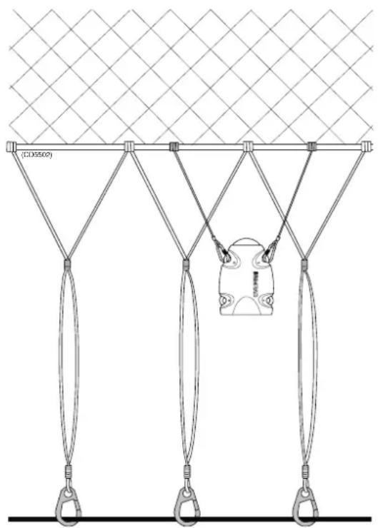
Figure 94 - Footrope attachment
The benefits of attaching sensors to the footrope are they:
- Are located outboard of the bulwarks when shooting and are deployed directly into the sea avoiding contact with the vessel.
• Hang relatively vertically when pursuing.
The disadvantage of attaching sensors to the footrope are they:
- Are difficult to remove before they pass through the power-block.
Attaching depth sensors to the footrope (tuna)
Sensors are attached utilizing strops that are spliced directly to the footrope and have karabiners at each end which are secured to the unit's topmost fastening lugs. The karabiners may also be bent directly to the chain which is secured to the footrope at a distance of 10 to 15cm. The separation should be such that a bridle is created suspending the sensor so that it is correctly orientated. Alternatively, the bights of rope may spliced directly to the footrope and the sensor's topmost fastening lugs. Permanently securing the sensors removes any possibility for quick disconnection and care must be exercised when charging to avoid personal injury due to electrical shock and possible electrolysis damage to the sensors' fastening lugs (refer to the previous cautionary note). This method of attachment requires that the sensor pass over the bulwarks or transom when the net is shot and therefore it must be properly secured to withstand the extreme forces involved.
Unstable communication between the hydrophone and sensors while the net is sinking, later stabilizing as the sinkrate decreases, is a sign that the sensors are not maintaining their vertical orientation. A solution to this problem is the attachment of approximately two to three kilos of ballast to the bottom of the sensors. Added weight will improve the vertical stability of the sensors as they sink.
→ Refer to figure 95.
The benefit of attaching sensors to the footrope (tuna) are they:
- Hang vertical when deployed and their orientation is negligibly effected when pursuing.
The disadvantage of attaching sensors to the footrope (tuna) are they:
- Follow the same path as the purse seine when hauling and shooting and may be subject to abuse.

Figure 995 FooFootrope attachment (tuna)
Attaching depth sensors to the net wall (tuna)
Sensors are attached utilizing strops that are spliced directly to the footrope and have karabiners at each end which are secured to the unit's bottommost fastening lugs. The karabiners may also be bent directly to the footrope at a distance of 10 to 15cm. The separation of the strops should be such that a bridle is created suspending the sensor so that it is correctly orientated. The sensor's topmost fastening lugs are secured to the net wall using elastic strops tensioned so that the units are held in a stable position.
Alternatively, the bights of rope may spliced directly to the footrope and sensor's bottommost fastening lugs. Permanently securing the sensors removes any possibility for quick disconnection and care must be exercised when charging to avoid personal injury due to electrical shock and possible electrolysis damage to the sensors' fastening lugs (refer to the previous cautionary note). Attachment of the sensors to the net wall may help to reduce the amount of abuse the units are subject to when the purse seine passes over the bulwarks or transom.
→ Refer to figure 96.
The benefits of attaching sensors to the net wall (tuna) are they:
- Are slightly better protected when shooting.
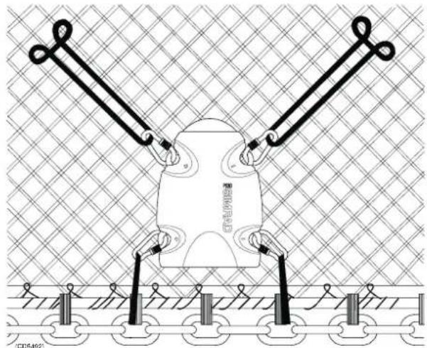
natural_image
Technical illustration of a robotic device with two arms and mounting base, set against a grid-patterned background (no text or symbols)Figure 906 NetNet wall attachment (tuna)
- Maintain their vertical orientation as the net sinks.
The disadvantage of attaching sensors to the net wall (tuna) are they:
- Oriented in the same direction as the net wall when pursuing which may provide poor communication with the hydrophone.
Conclusion
This information is a basic guide to attaching sensors to a purse seine and not a substitute for common sense, good seamanlike practices or experience. Each installation must be considered individually and the best solution determined with regard its particular characteristics.
11 HYDROPHONE INSTALLATION
11.1 Overview
Hydrophone location
Correct installation of the PI30 Hydrophone is vital to the system's performance. Several variables must be taken into consideration, the most important of which is the vessel's construction. This guide is for use in selecting the best location for the hydrophone and includes a brief description of areas to be avoided.
Depth
Water just below the sea surface contains a myriad of small air bubbles created by the turbulence of breaking waves. The first five to ten metres may be heavily saturated in moderate seas with the greatest concentration and largest bubbles closest the surface.
Air bubbles disrupt sound waves in water. The degree to which they absorb and reflect such energy vary, but in some cases they can block hydrophone reception. It is therefore recommended to mount the unit as deep as possible.
Pounding danger
When a vessel is in ballast and pitching in heavy seas, it is important that the hydrophone not be lifted out of the water. Should a vessel pound so heavily that the hydrophone be exposed, sound reception will be interrupted and the unit may be damaged on impact.
The boundary layer
The flow of water in the immediate vicinity of the hull of a moving vessel is known as a boundary layer. This flow is responsible for underwater noise that can disturb hydrophone reception and its thickness is contingent on a vessel's:
•Hull form
- Size and number of underwater protrusions
• Velocity
•Hull roughness
The boundary layer is thin (laminar flow) near the vessel's bow and becomes thicker (turbulent flow) as it moves aft. Laminar flow is smooth with streamlines approximately parallel to the hull and contributes relatively little to noise created by flow. Conversely, turbulent flow is more disorderly and in turn contributes to a greater extent.
Air bubbles may also be introduced into the boundary layer. If the vessel's hull has little flare and is relatively narrow, bubbles may escape to the sea surface without incident. On the other hand a wide, flat hull with minimal deadrise is prone to trapping air bubbles no matter how little flare it has. Regardless of a vessel's hull form, hydrophones are generally recommended to be installed on the forward part of the hull to minimising the influence of both turbulence and air bubbles.

Figure 97 - An exaggerated view of the boundary layer.
Bulbous bow
The bulbous bow may be an acceptable hydrophone location. Should this position be chosen, the foremost part of the bulb is often best, but also the most susceptible to pounding.

Figure 98 - Hydrophone location on a bulbous bow
Propeller noise
When shooting the purse seine the main propeller is the dominant source of under water noise. The hydrophone should be placed as far away as practical and outside its line-of-sight.
Bow/sternthruster noise
Bow and sternthruster operation may severely effect hydrophone reception. Hydrophone installation closer than four meters to either is strongly discouraged.
When not in operation, bow/sternthruster tunnels create turbulence and hence underwater noise when a vessel is under way. Also, as a vessel pitches in heavy weather, thruster tunnels may fill with air or aerated water which can disturb hydrophone reception when released. Hydrophone installation should take into regard the noise and down stream disturbances found around and aft of thrusters.
Noise from protruding objects and other sources
The primary sources of underwater disturbance (other than a vessel's main propeller and bow/sternthruster) that affect hydrophone reception are:
- Main or bilge keels
- Zinc anodes
• Cooling elements protruding from the hull
• Equipment such as sonar hydrophones and pitot tubes - Sea chests
• Overboard discharges - Dents in the hull
All appendages to the hull, indentations and pipe outlets are potential sources of underwater noise. They may act as resonant cavities amplifying noise at certain frequencies, create cavitation or turbulence. Hydrophones should not be located in the vicinity of such objects and especially not immediately aft of them.
Optimal location
The most influential factors effecting hydrophone reception common to most vessels are: noise from the main propeller, bow/sternthrusters and air bubbles. Taking these main sources of disturbance into consideration, the generally recommended location for mounting a single hydrophone is approximately one third the vessel's water-line length from the bow.
Installations requiring the use of two hydrophones may position the first as described above and the second forward of the bowthruster in conjunction with the transducer shoe for the echo sounder. Both hydrophones must be located at least four meters from the bowthruster.
Optimal hydrophone placement differs from vessel to vessel. Variables effecting hydrophone performance must be understood so that the best location may be chosen given a vessel's design and particular operation.

Figure 99 - Recommended fore and aft locations for single hydrophone installations (both locations are used with dual installations).
11.2 Hydrophone coverage area, horizontal orientation and tilt
General
Once the fore and aft placement of the hydrophone is decided, it is equally important to carefully consider its horizontal and vertical orientation. Hydrophone orientation can have a large influence on system performance.
The hydrophone's beam sensitivity is concentrated within a 90^ horizontal and -30^ vertical sector. Both keel and hull installations are to be located on the side of the vessel that the seine is shot.
Note!
These installation instructions and related drawings are for vessels shooting and pursuing to STARBOARD.
Horizontal coverage area
When the seine is normally located forward of the starboard beam when pursuing the following information should be taken into consideration:
- When the seine is pursed in the sector from approximately 000^ to 120^ relative to the bow, the hydrophone should be installed at an angle of 70^ to the vessels centre line.
→ See figure 100.

Figure 1000 To Top view of the PI30's horizontal coverage area. The hydrophone is installed at an angle of 70^ to the vessel's centre line.
- When the seine is pursed in the sector from approximately 030^ to 150^ relative to the bow, the hydrophone should be installed at an angle of 90^ to the vessel's centre line.
The most important elements with regard to the horizontal coverage area of the hydrophone are:
- An unobstructed line-of-sight to the PS30 sensor(s) attached to the purse seine.
•The hydrophone is directed at the middle of the net when pursuing.
- Two hydrophones may be used for applications requiring a large coverage area, see the section on Dual hydrophone installation for more information.
Vertical coverage area
The hydrophone has a vertical beam width of -30^ and should be tilted so that the most important part of the seine is adequately covered. Tilt should be no less than -15^ in most instances with the optimal tilt angle depending on the size (length/depth) of the seine in use. Heeling of the vessel after the seine is set must also be taken into consideration. For a large purse seine (about 1000m or longer) the recommend a tilt angle is -15^ plus the estimated angle of heel when the net is set. For smaller and deeper seines it may be necessary to increase the tilt angle.
Tilt angle
The tilt angle is a function of net length and depth and may be estimated as follows:
$$ \alpha = - [ \text { and } \text { tan } = (\text { depth / length } * \pi) - 1 5 ^ {\circ} + \beta ] $$
$$ \alpha = = \text { tilt } = \text { angle } $$
= angle = of = heel = (to = port) = after = deploying = the = purse = seine = to starboard
The=following=table=gives=some=examples=of=recommended=tilt anglesforcommonsizepureseines:
| Recommended=tilt=angles | ||||||
| Net=length/depth in met | 250/50s | 350/100 | 650/150 | 850/180 | 1500/200 | 2000/200 |
| Recommended tilt=angle=* | -15° | -25° | -20° | -20° | -15° | -15° |
*The=tilt=angle=should=be=increased=accordingly=if=the=vessel heels after the seine is shot. Tilt angles of less than -15° are not=recommended.
11.3 Hydrophone mounting arrangement
General
The=PI30=hydrophone=is=delivered=ready=for=installation=in=either a free-standing or keel mounted shoe built by the shipyard. Several=alternatives=with=corresponding=detailed=drawings=have been included in these instructions to cover the majority of installations. Specific information regarding through-hull penetration=is=described=in=the=respective=installation=drawing.
The=enclosed=installation=drawings=are=as=follows:
→ PI30 hydrophone outline dimensions (830-202893), page 113.
→ Keel-mounted hydrophone, steel or aluminium (821-203060), page 114 to 116.
→ Keel-mounted hydrophone, hull of sandwich or wood (821-202912), page 117 to 119.
→ Hydrophone in blister (821-203072), page 120 to 122.
Keel mounted shoes
The hydrophone shoe may be keel mounted to avoid creating an appendage to the hull which may foul the purse wire.
→ See figure 101.
Should=this=solution=be=chosen,=the=following=must=be=taken into consideration:
- The=hydrophone=must=have=an=unobstructed=line-of-sight=to the=PS30=sensor(s)=attached=to=the=seine.

Figure 1001- Ke Keel mounted hydrophone shoe
- The centre of the hydrophone's beam should be directed as much as possible toward the bottom of the net where the PS30 sensors are located. The tilt angle should be increased with regard to the expected heel of the vessel.
- For a short and deep seine a tilt angle of 20^ to 25^ is recommended. For a short and shallow or large seine a 15^ tilt angle may be best.
- If monitoring of the headline under pursing is desired the hydrophone should not be tilted more than 15^ .
•The hydrophone shoe should be mounted as deep as possible on the keel, but not so deep that it may be damaged while docking.
•The hydrophone shoe should be streamlined to avoid creating turbulence and underwater noise. See the enclosed drawings for more information. - For applications that require extensive coverage, regardless of net size, several hydrophones may be installed with different tilt angles. See the section on Dual hydrophone installation for more information.
Freestanding hydrophone in blister
If there is no risk that hull protrusions will be fouled by the purse wire, mounting the hydrophone in a freestanding blister is a viable option.
→ See figure 102.
Should this solution be chosen, the following must be taken into consideration:

Figure 1002-Fr Freestanding hydrophone in blister
- The centre of the hydrophone's beam should be directed as much as possible toward the bottom of the net where the PS30 sensor(s) arelocated. The tiltangles should be increased regard to the expected heel of the vessel.
- For a short and deep seine a tilt angle of 20^ to 25^ is recommended. For a short and shallow or large seine a 15^ tilt angle may be best.
- If monitoring of the headline under pursing is desired the hydrophone should not be tilted more than 15^ .
- For applications that require extensive coverage, regardless of net size, several hydrophones may be installed with different tilt angles.
• See the enclosed drawings for more information on freestanding hydrophones.
Dual hydrophone installation
Large vessels and operations requiring a greater than normal coverage area can install two hydrophones with a vertical and horizontal overlap. Hydrophone selection is made with the help of a switch located in the wheelhouse.
To reduce the possibility of interference from air bubbles and underwater noise when reversing propulsion or using thrusters the two hydrophones should be located at least five meters from each other in the fore and aft plane. It is also recommended to install the two hydrophones with a slightly different tilt angles so that a larger vertical sector may be covered.
Vessels equipped with a bowthruster or bulbous bow can install the first hydrophone forward of the bowthruster on the bulbous bow and the second aft of the bowthruster.
→ See figure 99 on page 95.
Dual hydrophone installations may be either keel mounted or installed in free-standing blisters.
Dual hydrophone horizontal coverage areas
When the seine is normally located forward of the starboard beam when pursuing the following information should be taken into consideration:
- When the seine is pursed in the sector from approximately 000^ to about 130^ relative to the bow, the fore-most hydrophone should be installed at an angle of 50^ and the after 90^ to the vessel's centre line.

Figure 103 - Horizontal coverage area of a dual hydrophone installation
- Should special circumstances require coverage outside the standard 000^ to 130^ sector the hydrophones may be installed accordingly.
Dual hydrophone vertical coverage area
When the seine is normally located forward of the starboard beam when pursuing the following information should be taken into consideration:
•The optimal tilt angle for dual hydrophone installations is derived in the same manner as a for single hydrophone installations. Consult the section on Tilt angle for more information.
•The hydrophones should be tilted so that the most important part of the seine is adequately covered. Tilting the forward hydrophone -25^ and the after -15^ will provide proper coverage in most instances.
→ See figure 104.
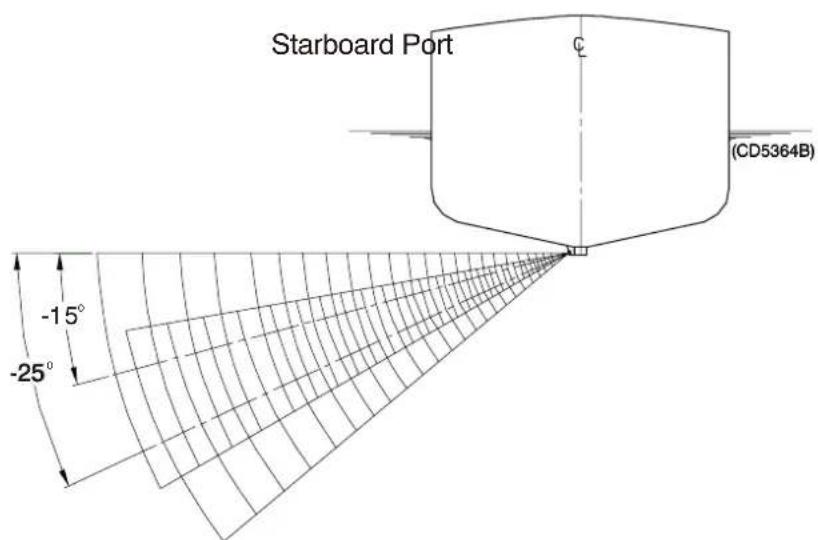
Figure 104 - Vertical coverage area of a dual hydrophone installation
- Tilt should be no less than - 15^ in most instances with the optimal tilt angle depending on the size (length/depth) of the seine in use.
- Heeling of the vessel after the seine is set must be taken into consideration when calculating the tilt angle.
11.4 Portable hydrophone
A portable hydrophone has been developed to be used temporarily until a fixed hydrophone can be installed at the vessel's next dry docking. Unlike permanently mounted units, the portable hydrophone has an omni-directional beam. It can also be lowered below the level of high underwater noise and air bubbles generated by the main propeller and bow/sternthrusters which can block reception of hull mounted units. The hydrophone's cable is 50 meters long and sheathed in polyurethane providing robust external protection to compliment its 150 kg tensile strength.
When the seine is normally located forward of the starboard beam when pursuing the following information should be taken into consideration:
•The portable hydrophone is to be deployed over the port side of the vessel, midships, as far away from bow or sternthruster(s) used when pursuing as possible.
- Note that the portable hydrophone's location is opposite to that of a permanently mounted unit. When pursuing to starboard the hydrophone is normally lowered over on the port side of the vessel.
→ See figure 105.

Figure 1005 Po Portable hydrophone
- The hydrophone cable should be made fast to the vessel's bulwarks.
- Sharp edges that could damage the hydrophone cable insulation should be avoided and the cable lying on deck should not be walked on.
•The hydrophone cable should not be knotted and kinking must be avoided.
•The hydrophone should be lowered deeper than the vessel's keel. - Special care should be taken so that the hydrophone or cable do not become fouled in the main propeller, thrusters or gear.
Storage
The portable hydrophone and cable should not be left on deck when not in use and stored with the following general precautions:
- Cleaned with fresh water after use.
- Care taken so that the cable does not chafe due to motion of the vessel.
- Contact with sharp edges that could damage the hydrophone cable insulation avoided.
•The hydrophone cable should not be knotted or kinked.
11.5 Installation precautions
Caution!
The following precautions must be observed. Failure to do so can result in damage to the hydrophone which may rendering the PI30 Purse seining system inoperative.
1 Observe the maximum allowable torque warning of 5 Nm when tightening the hydrophone studs.
2 Use only M8x30 (reg. no. 560-095360) socket countersunk head screws for mounting the hydrophone.
3 Secure threaded hydrophone hardware with Loctite™ 270 or the equivalent.
4 Do not paint the hydrophone.
5 Do not sand- blast, power or steam wash the hydrophone.
6 Do not scrape the hydrophone with metal or other hard objects that may damage the polyurethane sheathing.
7 Do not strike the hydrophone.
8 Do not expose the hydrophone to harsh chemicals.
9 Do not perform hot work in the vicinity of the hydrophone.
10 Do not lift the hydrophone by its cable.
11.6 Cable layout
General
The following information is a general description of installation requirements for PI30 system cables. These instructions must be used together with the applicable cable plans.
Note!
All cable connections and related installations must be made in accordance with the guide-lines set forth by the vessel's classification society.
→ See figures 106 and 107 on pages 104 and 105.
11.7 Cable specifications
The cables identified in the cable plan are listed according to cable identification number and type.
→ See table 3 on page 106.
PI30 Cable layout and plug diagram

NOTE: Cabinet connectors (male pins) are illustrated as seen from the back of the cabinet. Cable connectors (female sockets) are their corresponding mirror images.
Figure 1006 PI PI30 cable layout and plug diagram
PI30 Cable plan
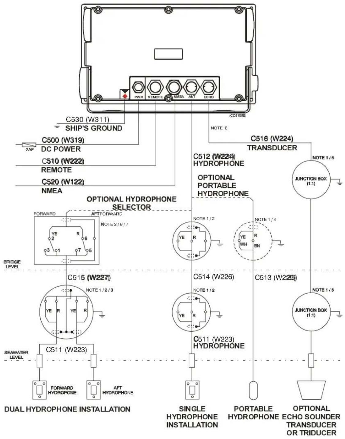
Figure 1007- PI PI30 cable plan (refer to page 106 for note descriptions)
| ID Type Specification | |||
| Power cable | |||
| C500 W319 | Manufacturer's supply (298-078426) | Ship's DC power supply to PI30 cabinet (integrated fuse and connector). | |
| Signal lines | |||
| C510 W222 | Manufacturer's supply (298-078427) | PI30 Cabinet to DE30 remote display. Maxi-mum distance 15m. | |
| C511 W223 | Cable moulded to the Hydrophone. | Hydrophone to cabinet via hydrophone plug and junction box if required. Supplied in 22m lengths. | |
| C512 W224 | Manufacturer's supply (370-078423). | PI30 cabinet to hydrophone cable, supplied in 3m lengths. | |
| C513 W225 | Manufacturer Supply Portable | hydrophone, supplied in 50m lengths of stretch-proof cable + 10m PVC shielded cable with an integrated seven pin plug. | |
| C514 | W226 | 1 x 2 x 0,5 mm2, twisted pair, overall braided. | Hydrophone to cabinet via junction box, single hydrophone installation. |
| C515 | W227 | 2 x 2 x 0.5 mm2, twisted pairs, overall braided. | Hydrophone to cabinet via junction box, dual hydrophone installation. |
| C516 W224 | Manufacturer's supply (370-078423) | PI30 cabinet to optional echo sounder trans-ducer. | |
| Serial lines | |||
| C520 | W122 | Manufacturer's supply (298-078425) | PI30 cabinet to NMEA serial data In/Out. |
| C530 | W311 | 1 x 6 mm2 | PI30 cabinet to ships ground. Keep as short as possible. |
Table 3 Cable specifications
Notes
The following notes refer to the PI30 cable plan:
Caution!
Use a multimeter to check for continuity. DO NOT subject the PI30's wiring or related components to high voltage.
Note 1 - Local supply
Note 2 - The hydrophone is delivered with a 22m long cable that may be spliced if necessary. Junction boxes made of metal must be grounded. Cable shielding must be continuous, it is terminated in the cabinet and must not be grounded in the junction boxes. The cable consist of six individual wires and a shield, only two of the wires (YE and R) are used. The topmost wires (BK, BL, and GN) are not to be connected. Simrad recommends running the cable between the hydrophone and PI30 cabinet through metal conduit to minimize electrical interference.
Note 3 - After making the connection, check continuity between the plug and the wires in the hydrophone's cable with the transducer selector in the forward and aft positions as follows:
• PiRirl 1to the red wire.
• Pin 7 to the yellow wire.
- Shielding is connected with pin 4, not grounded.
Note 4 - The portable hydrophone is delivered with a 50m stretch-proof cable (150kg tensile strength) consisting of a twisted pair, connected to a 10m PVC sheathed cable equipped with a seven pin plug for direct connection to the PI30 cabinet. If necessary the PVC sheathed cable may be spliced. Use a junction box constructed of mental which is grounded. The hydrophone cable's shielding is terminated at the plug and must not be terminated at the junction box.
Note 5 - Refer to the respective installation instruction for the connection of an echo sounder transducer.
Note!
The PI30's echo sounder is designed for use with a high-impedance ceramic traducers, it may be therefore necessary to employ a matching transformer should a low-impedance transducer is used.
Note 6 - Selection between the forward and aft hydrophones can be accomplished using a two-poll switch (Simrad reg. no. 351-078450 or equivalent). Cable shielding must be continuous, it is terminated in the PI30 cabinet and must not be grounded in the junction box or transducer selector.
Note 7 - Terminal numbers refer to Simrad's hydrophone selector (forward hydrophone, position 1/5; aft hydrophone position 3/7).
Note 8 - If an optional echo sounder transducer is installed, the PI30 becomes a fully functional echo sounder with the ability to superimpose sensor data over the echo sounder display for comparison.
12 TECHNICAL SPECIFICATIONS
12.1 General
A complete PI30 Purse einesystem consist of the follow i
• A display and control unit with LCD and keypad
• A hull mounted or portable hydrophone
•Up to three sensors
• A battery charger
12.2 Physical dimensions

Figure 108 - PI30 dimensions
12.3 Specifications
The following specifications are subject to change without notice:
| PI30 cabinet | |
| Power supply | 10-32VDC |
| Power drain | 15-18Watts |
| Environment | 0 to +50°C, Waterproof (USC 46 CFR and IP55) |
| Dimensions | 144x252x70mm / 1.5kg(5.8x10x2.8in / 3Lbs) |
| Display | 5.5inch 320x240 pixels TFT,power back-light |
| Interface facility | 1 port in/out NMEA0183, 1 port in NMEA0183 |
| Sensor receiver and display section | |
| Frequency band 43.5- 49.5kHz | , multi-channel DSP- receiver |
| Channels 3/30 | |
| Numeric display 3 sections, e | asy to read digital sensor display |
| Graphic display Historic plot | with digits showing actual sensor data and net behaviour |
| Status display Displaying sensor data, status and diagnostic tools | |
| Alarms | Both visual and audible alarm for maximum or minimum sensor data values |
| Navigation section* | |
| Position display Ship's position | speed, course and depth |
| Navigation display | Navigation highway with waypoints and cross track error |
| Echo sounder section** | |
| Frequency | 50/200 kHz, user selectable |
| Output power | 500W RMS |
| Depth range | Up to 350m at 200kHz and 800m at 50kHz |
| Pulse length | 50kHz: 1ms, 200kHz: 0.25 - or 1ms |
| Max ping rate | 8 pings per second |
| Alarms | Fish, maximum and minimum depth |
| Zoom mode | Bottom and VRM expansion |
| Split screen | Depth and A-scope, depth and bottom expansion, depth and VRM expansion |
| Event marker | At current ping |
| Scroll speed | True distance or time (3 steps + x2, x4, x8), 1 step/ping an freeze |
| Signal threshold User selectable on/off | |
| Fish detection White line discrimination | |
| Surface sea- water temperature | Transducer*** or NMEA |
| Ship's speed through the water | Transducer*** or NMEA |
| PS30 Depth and temperature sensors | |
| Housing Shock absorbing and | abrasive resistant Polyurethane |
| Karabiners Supplied with two | stainless steel karabiners for attachment to purse seine. |
| Corrosion resistance All metal | parts made of high grade Titanium to eliminate corrosion |
| Visibility | Coloured Hyper yellow to maximise visibility |
| Power | Rechargeable batteries, normal charge |
| Operational life between charges | approximately 30 hours |
| Range | 600 to 700m, purse seine application |
| Update rate | approximately 4.5Sec |
| Encoding | Field programmable channel selection |
| Maximum operating depth | 600m |
| Dimensions | 245x172x123mm |
| Weight | Weight in air/water approximately 4.2kg/1.4kg |
| PS30 Depth sensor | |
| Measuring range | 0 to 290m |
| Accuracy | +- 0.25% of full scale |
| PS30 Temperature sensor | |
| Range | -5°C to +30°C |
| Accuracy | +- 0.25°C |
| Hull mounted hydrophone | |
| Beam width 90°horizontal, -30°vertical,recommended tilt 15°to 25° | |
| Hydrophone cable Length: 25m, diameter: 6mm,terminated with 7 pin female connector | |
| Portable hydrophone | |
| Hydrophone and cable Strain | resistant, length: 50m supplied on storage reel |
| Battery charger | |
| Power supply 220VAC, 110V | AC or 24VDC |
| Charging Constant current, 50mA | |
| Options | |
| Remote display | DE30 Echo-sounder transducer |
| Wire strop for sensor attachment | |
| Rubber strop for sensor attachment | |
| Stuffing tube in plastic | |
| Stuffing tube, bronze | |
*Requires an external GPS navigator
**Requires an optional echo-sounder transducer
***Requires an optional triducer (depth, temperature and speed)
13 INSTALLATION DRAWINGS
The enclosed installation drawings are as follows:
→PI30 hydrophone outline dimensions (830-202893), page 113.
→Keel-mounted hydrophone, steel (821-203060), page 114 to 116.
→Keel-mounted hydrophone, hull of sandwich or wood (821-202912), page 117 to 119.
→Hydrophone in blister (821- 203072), page 120 to 122.
Note!
The drawings," Keel mounted hydrophone, steel" number 821-203060 on page 115 and "Keel-mounted hydrophone, hull of sandwich or wood" number 821-202912 on page 118 have both single and dual (forward/aft) hydrophone blisters superimposed on top of each other.
→See figure 109.
Single hydrophone installation
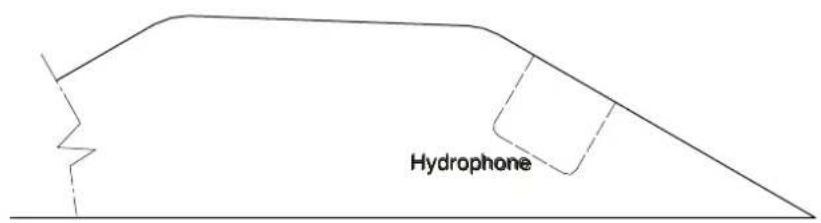
Dual hydrophone installation, forward blister

Dual hydrophone installation, aft blister

Figure 109 - Single and dual hydrophone installations

| The hydrophone cable (6.5mm in diam. supplied in 25m length) to be protected with steel pipes to above waterline DNV approved cable penetration in carbon steel: St52.3 (EN 10025). Simrad reg.no. 599-202216 The welding to hull structures and structural support of the cable penetration is subjected to separate approval for each installation ø35 ø65 100 Note 1 PL 6 appr. 400 (min.250) Note 2 Contour of bottom/keel Drainhole min. 25 | ||
| Note 1: Install the hydrophone on the side of the ship corresponding to the direction which the Purse Seine is set, normally on the starboard side Note 2: The beam angle of the hydrophone is 90° horizontally and 30° vertically. Recommended tilt angle ca. 15-25° dependent on the application. To compensate for possible heel after shooting the purse seine, increase the tilt angle of the hydrophone accordingly | ||
| Page 1 of 3 (CD5362) | Keel mounted hydrophone, hull of steel Cross section seen from bow Purse Hydrophone PI30 | 821-203060 Rev.A |
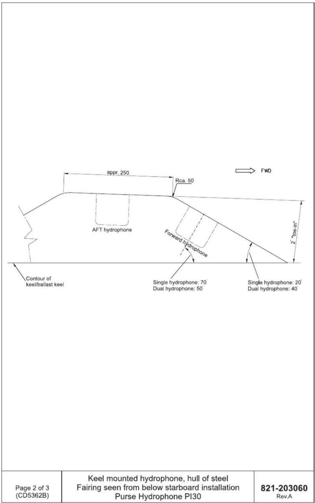
other
| Component | Dimension | | ---------------------- | ----------------- | | AFT hydrophone | FWD | | Forward hydrophone | 2" toe-in" | | Single hydrophone | 70 | | Dual hydrophone | 50 | | Single hydrophone | 20' | | Dual hydrophone | 40 |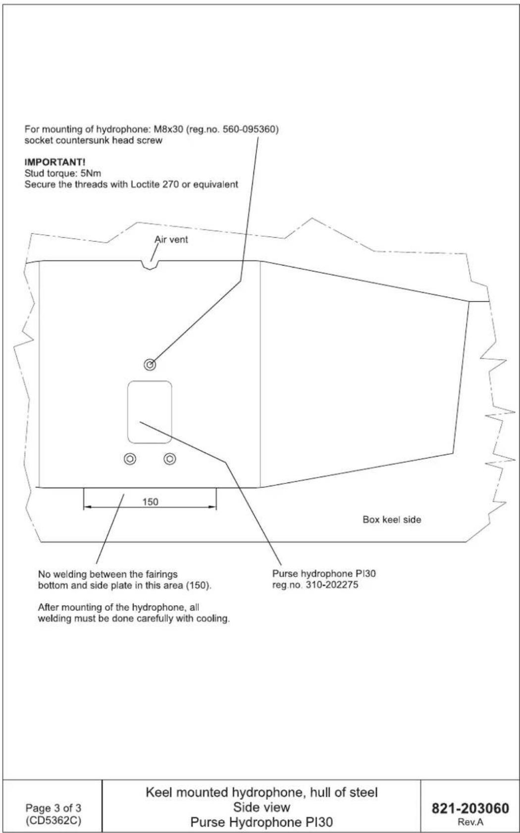
| The Hydrophone cable (6.5mm in diam. supplied in 25m length) to be protected with 1" pipes if required | ||
| See PI30 cable plan | ||
| Stuffing box in bronze, Simrad reg. no. 499-035266 | ||
| Hole for Simrad stuffing box in hull: Ø28 | ||
| Note 1 PI 6 ca. 400 (min. 250) Note 2 Drainhole Contour of bottom/keel min 25 | ||
| Note 1: Install the hydrophone on the side of the ship corresponding to the direction which the Purse Seine is set, normally on the starboard side | ||
| Note 2: The beam angle of the hydrophone is 90° horisontally and 30° vertically. Recommended tilt angle ca. 15-25° dependent on the application. To compensate for possible heel after shooting the purse seine, increase the tilt angle of the hydrophone accordingly | ||
| Page 1 of 3 (CD5361) | Keel mounted hydrophone, hull of sandwich or wood Cross section seen from bow Purse Hydrophone PI30 | 821-202912 Rev.A |
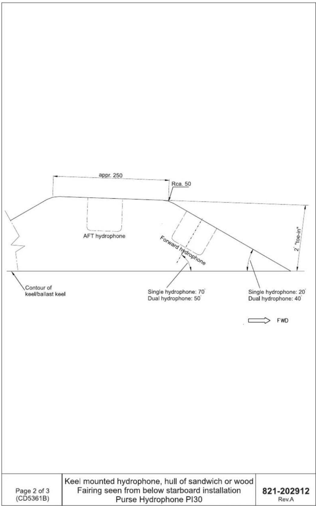
other
| Component | Dimension | | ---------------------- | ----------------- | | AFT hydrophone | Rca. 50 | | Forward hydrophone | 2"toe-in" | | Single hydrophone | 70° | | Dual hydrophone | 50° | | Single hydrophone | 20° | | Dual hydrophone | 40° | | FWD | → || For mounting of hydrophone: M8x30 (reg.no. 560-095350) socket countersunk head screw IMPORTANT! Stud torque: 5Nm Secure the threads with Loctite 270 or equivalent | ||
| Air vent | ||
| Box keel side | ||
| Purse hydrophone PI30 reg. no. 310-202275 | ||
| Page 3 of 3 (CD5361C) | Keel mounted hydrophone, hull of sandwich or wood Side view Purse Hydrophone PI30 | 821-202912 Rev.A |
| The hydrophone cable (6.5mm in diam. supplied in 25m length) to be protected with steel pipes to above waterline DNV approved cable penetration in carbon steel: St52.3 (EN 10025) Simrad reg.no. 599-202216 The welding to hull structures and structural support of the cable penetration is subjected to separate approval for each installation ø35 ø65 appr.400 (min. 250) PL6 Drainhole Note 1: Install the hydrophone on the side of the ship corresponding to the direction which the Purse Seine is set, normally on the starboard side Note 2: The beam angle of the hydrophone is 90° horizontally and 30° vertically. Recommended tilt angle ca. 15-25° dependent on the application. To compensate for possible heel after shooting the purse seine, increase the tilt angle of the hydrophone accordingly | ||
| Page 1 of 3 (CD5375) | Hydrophone in blister, hull of steel Cross section seen from bow Purse Hydrophone PI30 | 821-203072 Rev.A |
| Page 2 of 3 (CD5375B) | Hydrophone in blister, hull of steel Fairing seen from below, starboard installation Purse Hydrophone PI30 | 821-203072 Rev.A |

14 GLOSSARY OFF TERMS
Alarms - can be activated when the PI30 detects a target above (shallower than) the minimum set alarm depth or below (deeper than) the maximum set alarm depth. The system allows alarm depths to be set individually and enabled or disabled as necessary.
A-Scope - a method of displaying echo sounder information where echoes are displayed in a bar-graph format. Stronger echoes may be differentiated from weaker by colour and width which corresponds to the strength of the return.
Colour threshold - a function that allows noise and weaker targets normally represented by blues and greens not to be shown by the selectively eliminating such colours from the display.
Configuration - are the setup parameters which allow the PI30 to be tailored to specific needs. The majority of displayed information including: units of measure, colours, language, scroll speed, window selection and other functions may be changed to suit a particular situation.
Default - initial setup parameters programmed by the factory.
Echogram background colour - the LCD background colour may be set to be black or white. Black is normally selected for night time operation.
Echo sounder frequency - may be set to either 200 kHz or 50 kHz employing narrow (15°) and wide (45°) transmitter beams respectively. For general purpose use the 200 kHz frequency offers optimum discrimination. The 50 kHz frequency is more effective when searching a wider area, determining bottom condition or operating at maximum depth.
Event marker - superimposes a vertical marker on the LCD at the location of the current ping to indicate for example a school of fish.
Expansion (zoom) - provides an enlarged view around a specified depth and may be adjusted in as required. The area near the bottom or variable range marker may also be magnified by using Bottom and VRM expansion functions respectively.
Gain - controls the PI30's sensitivity. Increasing the gain provides better return from smaller and deeper targets. Excessive gain will fill the LCD with unwanted targets known as “noise” and should be set to just below this point.
Interface - the electronic connection of one or more pieces of equipment allowing them to share data.
LOG speed calibration - the PI30 is calibrated at the factory to receive 19000 pulses per nautical mile using a paddle-wheel type log. Due to hydrodynamic differences between various installations this figure may have to be changed. The correct pulse rate may be calculated using the following equation:
$$ 1 9 0 0 0 \times \frac {S T W}{S O G} = P u l s e s / n m $$
STW= Speed Through Water from the vessel's speed log.
SOG= Speed Over Ground from the vessel's GPS.
Measurement units - in=the=range=display=are=in=either=meters, feet=or=fathoms.
MENU - an=on=screen=display=of=PI30's=functions=and=options navigable=using=the=cursor.
NMEA - The National Marine Electronics Association is a group of=equipment=manufactures=responsible=for=adopting=NMEA 0183=as=a=standard=for=interfacing=marine=electronics.
Ping to ping filter - Unfiltered echos are displayed on the LCD as=they=are=received.=Filtering=compares=sets=of=echoes=and=only display=those=received=twice=providing=a=more=precise=recording by=helping=to=eliminate=false=targets.
Pulse length - is=set=automatically=with=regard=to=depth=using PI30's=AUTO=function=or=manually=should=a=specific=pulse=length be=required.
→ Table 4 may be used as a guide for setting the pulse length manually.
| Pulse length | 50kHz | 200kHz |
| SHORT | less=than=5=m | less=than=5=m |
| MEDIUM | between 5 and 50m | between 5 and 50m |
| LONG | more=than=50m | more=than=50m |
| In=general=a=longer=pulse=will=travel=deeper,=but=will=provpoorer=resolution. | ||
Table 4 Recommended pulse length
Range --is=the=order=of=magnitude=with=which=depth=is=displayed on=the=LCD=limited=by=its=top=and=bottom=edges.=Range=is=selected automatically=using=the=AUTO=function=which=ensures=the=sea floor=is=shown=on=the=lower=half=of=the=LCD=or=it=may=be=set manually.
Range start - allows=the=displayed=depth=range=to=begin=at=a pre-determined=point=below=the=surface=.
Limitation!=With=the=White=line=feature=activated=at=the=same=time as=the=Range=start=happens=to=be=set=to=a=level=deeper=than=the actual=water=depth,=a=continuous=reset=sequence=will=commerce and=stay=on=until=the=water=depth=again=exceeds=the=level=entered for=the=Range=start.=If-you=are=not=about=to=return=to=deeper=water, we=suggest=that-you=disconnect=the=transducer=cable,=and=thus gain=access=to=adjust=the=Range=start,=either=to=zero=or=to=a=more appropriate=water=depth.
Note!
If the White line feature is activated when the Range start function is set at a water depth deeper than the actual depth, a continuous reset sequence will commence. The unit will continue to reset itself until the actual water depth exceeds the depth entered for the Range start function. Should a continuous reset situation arise and the vessel not be travelling toward deeper water, the transducer cable must be disconnected allowing the Range start depth to be changed to zero or a depth that will not result in the unit continuously resetting itself.
Scroll speed - is the rate of movement targets travel from right to left across the LCD. It may be adjusted to show a longer "history" if required.
Scroll synchronization - the screen can be updated on the basis of time or distance (when data from last ping appears on the display).
Signal threshold - removes unwanted noise using an automatically controlled threshold level. This function should be used with caution due to the possibility that small fish and other objects may be eliminated from the display.
Transducer - is the under water element of the system that both sends and receives acoustic signals which are used to determine the depth of objects.
TVG - Time Varying Gain - makes corrections for the majority of energy loss and absorption that occurs when sound waves pass through (sea) water. When making a selection in Presentation setup the best choice is normally Bottom 20logR. In shallower water the setting Fish 40logR gives a stronger return, but is more susceptible to surface noise.
White line - places a white or black line at the same depth as the sea floor shown on the LCD. By removing four pixels just below this line, targets that may have been obscured by the bottom are more easily identifiable.
VRM - Variable Range Marker is a controllable horizontal black line on the LCD that when oriented over a target displays its depth on the left side of the screen.
©Simrad AS
Simrad AS
Strandpromenaden 50
Box 111
N-3191 Horten
Telephone: +47 33 03 40 00
Facsimile: +47 33 04 29 87
www.simrad.com
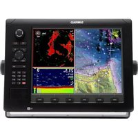
- Instruction manual
- Simrad PI30
- Purse seine instrumentation
- Note
- Warning
- Copyright
- Manufacturer:
- Sections
- Remarks
- The reader
- Tablire of contents
- SYSTEM DESCRIPTION 1....
- MENUS 7
- PROCEDURES 9
- REFERENCES 39.
- TROUBLESHOOTING 67
- MAINTENANCE AND REPAIR 69
- BATTERY CHARGING AND TESTING 71
- SYSTEM INSTALLATION 74
- SENSOR CONFIGURATION 78....
- DEPTH SENSOR ATTACHMENT 85
- HYDROPHONE INSTALLATION 92
- TECHNICAL SPECIFICATIONS 108
- INSTALLATION DRAWINGS 112
- GLOSSARY OF TERMS 123
- Document reevisions
- References
- Document history
- SYSTEM DESCRIPTION
- Overview
- General
- System components
- PI30 p#p#seiseine system primary functions
- Derivable purse seine information
- PI30 Display and control unit
- Display and control unit components
- LCD display
- Display and cocontrol unit keypad
- PS30 Depth sensor
- PS30 Temperature sensor
- Sensor codes
- Sensor charger
- Hull mounted Hydrophone
- Portable Hydrophone
- Service and repair
- MEENUSS
- Viewing and selecting menus
- Menu navigation
- Or
- PROCEDURE PRESS
- Getting started
- Power--up procedure
- Power--down procedure
- Master reset
- Adjust LCD and keypad lighting
- Selecting a display
- Selecting and changing parameters
- Display language
- Display windows
- Selecting the four display windows
- Editing the four display windows
- Manually changing display windows
- Automatically changing the display window
- To change the pre--selected time interval for window rotation
- Purse seine functions
- Activating the numeric display
- Edit numeric display setup
- Activating the graphic display
- Graphic display setup
- Activating the status display
- Status display setup
- Nav functions
- Activating the position display
- Resetting the log
- Activating the navigation display
- Navigation setup
- Navigation setup:
- Echo functions
- Activating the echo display
- Presentation setup
- Activating bottom expansion
- Activating VARM expansion
- Turn A--scope ON / OFF
- Turn VRM ON / OFF
- VRM keypad
- Echo sounderssetup
- Editing parameters
- Setup functions
- Speed alarm, units & language
- Setup for Speed alarm, units & language
- Interface setup NMEA
- Setup offNMMA interface
- Press ENT.
- Warning!
- ESCAPE: MENU PROCEED: ENT
- Press ENT.
- Move the cursor to the parameter to be changed.
- Repeat steps 3 and 4 until all desired changes have been made.
- Press ENT to confirm the changes.
- Press MENU to call up the menu bar and proceed to the next function.
- Interface setup remote/alarm
- Setup of remote/alarm interface
- PresPSENT.
- Sensor alarm/calibration
- Setup for sensor alarm/calibration
- Sensor calibration
- Sensor configuration & receiver setup
- Setup for sensor configuration & receiver
- Move the cursor to the Master reset drop-down menu.
- Reset
- REFERENCE
- Purse seine display references
- Overview
- Numeric display with three depth sensor windows
- Numeric display with two depth and one temperature sensor windows
- Numeric setup
- Variable parameters in the Numeric setup are:
- Graphic Display
- Graphic setup
- Variable parameters in the Graphic setup are:
- Status display
- Navigation display references
- Position display
- Log 1
- Log 2
- LAT
- LON
- Speed
- Course
- Depth
- Wattentenpp.
- Local time
- Local date
- Navigation display
- Navigation display information:
- C
- B
- D
- XTE
- Status
- Navigational display motorway
- Echo sounder display references
- Echo display
- Basic display information:
- Upper left-hand corner
- Upper centre
- Upper right-hand corner
- Across the centre
- Lower left-hand corner
- Presentation setup window
- Variable parameters in the Presentation setup window are as follows:
- Bottom expansion
- Bottom expansion information:
- Horizontal line
- Lower left-hand side
- Across the top 2/3
- Across the bottom 1/3
- VRM expansion
- VRM expansion information:
- A-scope
- A-scope information:
- Right side
- Vertical line
- VRM
- VRM information:
- Echo sounder setup
- Echo sounder setup information:
- PI30 Setup
- The Setup windows are:
- Speed alarm, units & language information:
- Interface setup and NMEA connector
- Interface setup NMEA information:
- Alarm setup:
- Depth sensor:
- Sensor alarm
- Sensor configuration & receiver setup information:
- Sensor configuration & receiver parameters
- Sensor configuration
- Channel selection
- Display colour
- Display colour information:
- TROUBBLESHOOTING
- General PI30 information
- PI30 Display and control cabinet
- No picture on the LCD
- LCD picture is too dark / bright
- Abnormal LCD picture
- Echo sounding picture appears normal, but no targets or only noise is displayed
- No response to keypad input
- No normal picture or keypad input
- MAINTENANCE AND REPAIR
- General
- Service
- Spare parts
- PI30 Display and control cabinet
- Surface cleaning
- Electrical connections
- PS30 Hydrophone
- Cleaning
- Dry dock
- PSS00 portable hydrophone
- Storage
- PS30 Depth and temperature sensors
- Extra protection
- BATTERY CHARGING AND TESTING
- Charging PS30 sensors
- When to charge the sensors
- Charging procedure
- Testing
- Normal condition
- Depleted battery
- Possible fault
- SYSTEM INSTALLATION
- General
- Planning
- Cable
- Sealed system
- Grounding
- Power source, fuse and power cable
- PI30 display and control unit
- Mounting
- Bracket mounting
- Mounting options
- Flush mounting
- Electrical connections
- Power supply connections
- Fuse
- Hydrophone connection
- NMEA 0183 interface connections
- SENSOR CONFIGURATION
- Necessary equipment
- Programming
- PS30 Sensor Configuration Software
- Connecting the PS30 sensor
- Changing sensor configuration
- Self-made programming cable
- Required parts
- Assembly procedure
- DEPTH SENSOR ATTACHMENT
- Coverage
- Attachment
- Attaching depth sensors to the purse line
- Attaching depth sensors to the bridle
- Caution!
- Attaching depth sensors to the footrope
- Attaching depth sensors to the footrope (tuna)
- Attaching depth sensors to the net wall (tuna)
- Conclusion
- HYDROPHONE INSTALLATION
- Overview
- Hydrophone location
- Pounding danger
- The boundary layer
- Bulbous bow
- Propeller noise
- Bow/sternthruster noise
- Noise from protruding objects and other sources
- Optimal location
- Hydrophone coverage area, horizontal orientation and tilt
- Horizontal coverage area
- Vertical coverage area
- Tilt angle
- Hydrophone mounting arrangement
- Keel mounted shoes
- Freestanding hydrophone in blister
- Dual hydrophone installation
- Dual hydrophone horizontal coverage areas
- Dual hydrophone vertical coverage area
- Portable hydrophone
- Installation precautions
- Cable layout
- Cable specifications
- Notes
- Note 1 - Local supply
- TECHNICAL SPECIFICATIONS
- General
- Physical dimensions
- Specifications
- INSTALLATION DRAWINGS
- GLOSSARY OFF TERMS
- Note!
Marque : SIMRAD
Modèle : PI30
Catégorie : Navigateur