
Galloper II (1997) - Voiture HYUNDAI - Notice d'utilisation et mode d'emploi gratuit
Retrouvez gratuitement la notice de l'appareil Galloper II (1997) HYUNDAI au format PDF.


| Type de produit | Véhicule utilitaire sport (SUV) |
| Marque | Hyundai |
| Modèle | Galloper II (1997) |
| Catégorie | Voiture |
| Longueur | 4 600 mm |
| Largeur | 1 800 mm |
| Hauteur | 1 800 mm |
| Poids à vide | 1 800 kg |
| Capacité du réservoir de carburant | 75 litres |
| Type de carburant | Diesel ou essence |
| Cylindrée du moteur | 2 500 cm³ (2.5 L) ou 3 000 cm³ (3.0 L) |
| Transmission | Manuelle 5 vitesses ou automatique 4 vitesses |
| Nombre de places | 5 à 7 |
| Type de transmission | Propulsion ou 4 roues motrices |
| Freins avant | Disques ventilés |
| Freins arrière | Tambours |
| Pneus recommandés | 235/75 R15 |
| Intervalle de vidange d'huile moteur | Tous les 10 000 km ou 1 an |
| Batterie | 12 V, capacité 70 Ah |
| Système de sécurité | Ceintures de sécurité, airbags conducteur et passager |
| Entretien du filtre à air | Remplacement tous les 20 000 km |
FOIRE AUX QUESTIONS - Galloper II (1997) HYUNDAI
Questions des utilisateurs sur Galloper II (1997) HYUNDAI
0 question sur cet appareil. Repondez a celles que vous connaissez ou posez la votre.
Poser une nouvelle question sur cet appareil
Téléchargez la notice de votre Voiture au format PDF gratuitement ! Retrouvez votre notice Galloper II (1997) - HYUNDAI et reprennez votre appareil électronique en main. Sur cette page sont publiés tous les documents nécessaires à l'utilisation de votre appareil Galloper II (1997) de la marque HYUNDAI.
MODE D'EMPLOI Galloper II (1997) HYUNDAI
GALLOPERII
OWNER'S MANUAL

natural_image
Side profile sketch of a car (no text or symbols)GALLOPERII
OWNER'S MANUAL

FOREWORD
Thank you for choosing Hyundai. We are pleased to welcome you to the growing number of discriminating people who drive Hyundai vehicles. The advanced engineering and high-quality construction of each Hyundai is something of which we're very proud.
Your Owner's Manual will introduce you to the features and operation of your car. It is suggested that you read it carefully since the information it contains can contribute greatly to the satisfaction you receive from your new car.
The manufacturer also recommends that all service and maintenance on your car be performed by an authorized Hyundai dealer. Hyundai dealers are prepared to provide high-quality service, maintenance and other assistance that may be required.
Hyundai reserves the right to make changes in design and specifications and/or to make addition to or improvements in this product without obligation to install them on products previously manufactured. It is an absolute requirement for the driver to strictly observe all laws and regulations concerning vehicles.
This manual has been written in compliance with such laws and regulations, but some of the contents may become contradictory with later amendment of the laws and regulations.
HYUNDAI MOTOR COMPANY
NOTE : Because future owners will also need the information included in this manual, if you sell this Hyundai, please leave the manual in the vehicle for their use. Thank you.
Copyright 1997 HYUNDAI MOTOR COMPANY All rights reserved. The material in this publication may not reproduced in any form without written permission from HYUNDAI MOTOR COMPANY.

Table of contents
• Instruments and controls .... 2
• Safety precautions and driving tips .... 5
• Instruments.... 17
• Switches.... 27
• Key-locking and unlocking 35
• Interior equipment 41
• For pleasant driving 61
• Starting and driving 93
• Vehicle care ....109
• During cold weather 115
Do it yourself 119
• Emergency measures .... 133
Things you should know 151
Service data 153
Instruments and controls (without airbag)
![Windscreen wiper S/W Windscreen washer S/W Rear window wiper and washer Headlight washer switch* Meter and gauge Hazard warning switch Combination switch Rear fog lamp switch* Front fog lamp switch(Argentina only)* Rear heater switch* Front fog lamp switch [Innovation(EU)]* Rheostat Headlight leveling device switch * Bonnet release lever Ignition switch Engine rpm adjusting knob Front fog lamp switch* Hazard warning switch(EU)* Heated seats* Cigarette lighter Rear window demister Meter and gauge Heater and air conditioner control Clock Air conditioner switch* (only for Manual type) Ashtray Gear shift lever Transfer shift lever Selector lever* (automatic transmission) Overdrive switch* Outside rear view mirror switch* Rear air conditioner control lever* GVEO-0001](/content/2026/06/1315333/images/fa5d04911611b401ea3caed69fbb35c3340e15d0cc7b145a5e70072e669b2a07.jpg)
Optional equipment marked with an asterisk may differ according to the country it is sold in or the sales classification; refer to the sales catalogue.
Instruments and controls (with airbag)*
![Windscreen wiper S/W Windscreen washer S/W Meter and gauge Combination switch Air conditioner switch* (only for Manual type) Rheostat Headlight leveling device switch * Bonnet release lever Ignition switch Engine rpm adjusting knob Hazard switch Cigarette lighter Rear window demister Heated seats* Clock Meter and gauge Heater and air conditioner control Front fog lamp switch* Rear fog lamp switch(EU)* Front fog lamp [Innovation(EU)] Rear heater switch* Headlight washer switch* Ashtray Gear shift lever Transfer shift lever Selector lever* (automatic transmission) Overdrive switch* Outside rear view mirror switch* Rear window wiper and washer Rear air conditioner control lever* GVEO-0212](/content/2026/06/1315333/images/dfbd7c8737184f9779f1a334a9be8c868d4a6cc5cf6710dbd0f43c29f4c471c3.jpg)
Optional equipment marked with an asterisk may differ according to the country it is sold in or the sales classification; refer to the sales catalogue.
MEMO
Safety precautions and driving tips
Ignition switch
Carrying children
Seat and seat belt
Loading
Automatic transmission*
Brake system
Anti-lock brake system*
Parking
Power steering system
Turbocharger (diesel-powered vehicles)
Catalytic converter
(gasoline-powered vehicles)
Economical driving
Fuel usage (gasoline-powered vehicles)
Limited slip differential*
Ignition switch

Do not remove the ignition key from ignition switch while driving.
(1) If the key is accidentally removed while driving, the steering wheel will lock, making it impossible to control the vehicle.

natural_image
Cartoon illustration of a person sitting in a chair with a head turned, showing stress or discomfort (no text or symbols)(2) If the engine is stopped while driving, the brake servomechanism will cease to function and braking efficiency will deteriorate.
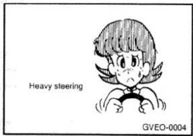
(3) If the engine is stopped while driving, power steering system will not function and it will require more manual power to operate the steering wheel.
Carrying children
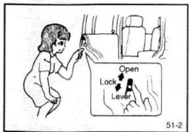
(1) Never leave a child in the vehicle unattended.
(2) If a child is seated alone in the rear seat, use the child protection system.
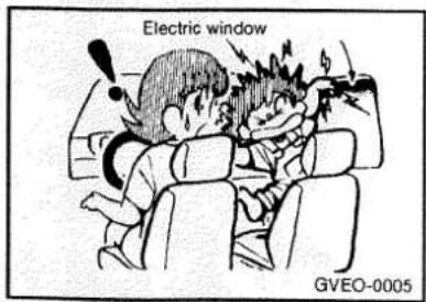
(3) Be careful of children's fingers when operating electric windows.
Seat and seat belt

(1) Never adjust the driver's seat while the vehicle is in motion.
Adjusting the seat while driving could cause the driver to loose control of the vehicle.
(2) Do not pile luggage or cargo higher than seatbacks for your safety.
(3) For technical reasons, the second seat and third seat should not be folded down to make a bed while the vehicle is being driven.
(4) To protect you and your passengers in the event of an accident, it is most important that the seat belts be worn correctly when you drive.
(5) The seat belt will provide maximum protection for its wearer if the recliner seatback is placed in its most upright position. When the seatback is reclined, there is greater risk that the passenger will slide under the belt, especially in a forward impact accident, and may be injured by the belt or by striking the instrument panel or seatbacks.
Loading
Loading should not be to the point at which the Maximum Gross Vehicle Weight, Maximum Front Axle Weight or Maximum Rear Axle Weight is exceeded.
Pay close attention to the following in order to maintain good driving characteristics:
(1) Secure loaded goods properly to keep them from breaking or flying off when the vehicle makes a sudden stop or turn.
(2) Always close the back door securely when driving to keep exhaust gases from entering the vehicle.
(3) Center loads over the axle as closely as possible. Placing them to the side or rear will unbalance vehicle height.
(4) Be cautious to keep loads from loosening or rubbing against the rear window to avoid damage to rear window hot wires.
Automatic transmission\*

(1) Before selecting a gear with the engine running and the vehicle stationary, fully depress the brake pedal to prevent the vehicle from creeping.
Because the vehicle will begin to move as soon as the gear is engaged, especially when the engine speed is high at fast idle or the air conditioner operating, the brakes should be released only when you are ready to drive away.
(2) Depress the brake pedal with the right foot at all times. Using left foot could cause driver moment delay to sudden maneuver in case of an emergency.
(3) To prevent sudden acceleration, never race the engine when shifting from the "P" or "N".
(4) Operating the accelerator pedal while the other foot is resting on the brake pedal will affect braking efficiency and may cause premature wear of brake pads.
Do not race the engine with brake pedal pressed. This can damage the transmission.
Brake system
All the parts of the brake system are critical to safety. Have the vehicle serviced by a GALLOPER dealer at regular intervals according to the service standards.

(1) The service brake is divided into two brake circuits so that when one brake circuit fails, the other is available to stop the vehicle. If this occurs, however, the brake pedal must be depressed further than usual; stop driving as soon as possible and have the brake system serviced at the nearest GALLOPER dealer.
(2) Do not leave any objects or place a thick floor mat around the brake pedal; doing so could prevent the full pedal stroke that would be necessary in an emergency. Make sure that the pedal can be operated freely at all times.
(3) If the vehicle is equipped with a brake warning lamp, the lamp will light up if the brake fluid level is abnormally low.
(4) If the vehicle is equipped with a brake booster, the brake boosting force is lost after the brake pedal is depressed once or twice while the engine is off. If this occurs, the brake will require greater force than usual.
This is especially important when the vehicle is being towed.
On diesel powered vehicles, the brake booster will no longer function if the V belt is broken. In this case, use engine braking (downshifting) to reduce the speed of the vehicle and then depress the brake pedal with more force than usual to stop the vehicle in a safe place.
(5) Check the brake system while driving at a low speed immediately after starting, to confirm that it works normally. A film of water can form on the brake discs and prevent normal functioning after driving in heavy rain or through large puddles, or after the vehicle is washed. If this occurs, repeatedly tap the brake pedal lightly while driving to dry out the brakes.
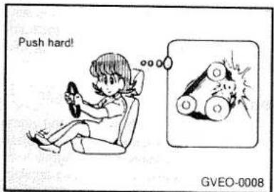
(6) It is important to take advantage of the braking power of the engine by shifting to a lower gear while driving on steep downhill roads in order to prevent the brakes from overheating.

(7) With new brake pads or linings, if possible, avoid applying the sudden brakes fully during the first 200km(124 miles) of driving.
(8) Operating conditions and driving habits influence the wear of the brake linings. In some cases, therefore, it may be necessary to have the thickness of the brake linings checked by a GALLOPER dealer at shorter intervals than stated in the Service Booklet, especially at relatively low mileages. This applies especially to people who drive mainly in the city or for short distances, as well as to those who have sporting driving habits.
Anti-lock brake system\*
(ABS)
When the brakes are applied on a moving vehicle, excessive force on the brake pedal or snow, ice, oil, etc., on the road surface could cause the vehicle to skid. If such a skid occurs, the braking force will be reduced and the braking distance increased, and the vehicle could turn sideways and go into a spin with the driver losing control.
The ABS prevents the wheels from locking during braking, thus maintaining directional stability, ensuring controllability, and providing optimum braking force.
Driving hints
(1) Even with the ABS, the steering wheel operation during sudden braking (when the ABS functions) differs slightly from when the brakes are not being applied. Be sure to operate the steering wheel carefully.
(2) Although the braking distance for vehicles equipped with an ABS is generally shorter than for those without, because this difference will vary according to the road condition and other factors, maintain the same distance from the vehicle in front of you as for a vehicle not equipped with an ABS.
(3) Also, because the braking distance on gravel or snowy roads may be longer than for a vehicle not equipped with an ABS, these roads should be driven at reduced speeds.
CAUTION
Even the ABS can not prevent the natural laws of physics from acting on the vehicle. It can not for instance avoid accidents that maybe resulting from excessive speed in turns, following another vehicle too closely or aquaplaning. It should remain driver's task with safety precautions to judge speeds and brake applications correctly in such conditions.
Parking

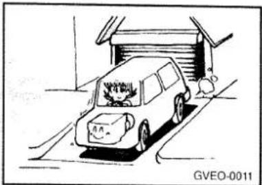
(1) When parking, fully engage the parking brake, and then set the gearshift lever to 1st or reverse for vehicles with manual transmission and set the selector lever to "p" position for vehicles with automatic transmission. (Set the transfer shift lever to any position except "N".) It is recommended, for additional safety, that wheel chocks also be used on a hill.
natural_image
Cartoon illustration of a car parked near a garage, with a person standing nearby (no text or symbols)(2) Do not keep the engine running for a long time in a closed or poorly ventilated place. Carbon monoxide gas is odorless and extremely poisonous and dangerous.

(3) Because the exhaust system produces high temperatures, avoid parking in a place where there are inflammable objects such as dry grass, rags, etc.
(4) Remove the key from the ignition switch when leaving the vehicle.
Power steering system

When the engine is stopped, the power steering system will not function and it will require more manual power to operate the steering wheel. Keep this in mind in particular when towing the vehicle. Never turn off the engine while driving. Periodically check the power steering fluid level.
Turbocharger
(diesel-powered vehicles)
If your vehicle is equipped with a turbocharger, do not stop the engine immediately after operating the vehicle at high speeds. Allow the engine to idle for approximately 60 seconds or more to give the turbocharger a chance to cool down.
Driving out of mud
If one rear wheel gets stuck in the mud and starts spinning, try using the following method to drive the vehicle out of the mud.

natural_image
Cartoon illustration of a car with a thought bubble showing a fish, no text or symbols present- Set the transfer shift lever to either "4H" or "4L" and use four wheel drive to drive the vehicle out of the mud.
- If it is still not possible to extract the vehicle, pull the parking brake lever slightly to just barely engage the brake (be sure not to engage it all the way) and try driving again. Depress the accelerator gradually, and don't forget to release the parking brake once the vehicle is out of the mud.
Catalytic converter (if installed) (gasoline-powered vehicles)

In normal use, there are no particular cautions regarding handling except for the use of lead-free gasoline. Exhaust gas purification systems equipped with the catalytic converter are extremely effective in reducing noxious gases. The catalytic converter is installed in the exhaust gas system. Because the catalytic converter becomes very hot after vehicle travel, the following points should be given attention to ensure safety.
• Do not park the vehicle near inflammable materials.
• Do not apply an undercoat to the catalytic converter.
The catalytic converter itself easily reaches high temperatures, and overheating may results in damage. Care should be taken regarding the following points to prevent unburned gasoline form adhering to the inside of the catalytic converter.
- Do not turn off the ignition switch while driving.
- Never start the engine by pushing the vehicle. If the battery is weak or dead use other battery to start engine.
- If engine trouble such reduces performance, irregular engine rpm, or ignition trouble occurs, stop the vehicle immediately. If travel must be continued it should be at low speeds and for short times. Contact your nearest GALLOPER dealer for inspection.
Economical driving

For economical driving, there are some technical requirements that have to be met. The prerequisite for low fuel consumption is a properly adjusted engine. In order to achieve longer life of the vehicle and the most economical operation, have the vehicle serviced by a GALLOPER dealer at regular intervals in accordance with the service standards. Fuel economy and generation of exhaust and noise are highly influenced by personal driving habits as well as the particular operating conditions. The following points should be observed in order to minimize wear of brakes, tyres and engine as well as to reduce environmental pollution.
(1) Starting
Avoid rapid acceleration and sudden starts; such operation will result in more fuel consumption.
(2) Shifting
Shift only at an appropriate vehicle speed and engine rpm. Always use the highest gear possible. When driving at high speed over public roads, fuel economy can become poor and noise levels rise. The transfer shift lever should be set to "2H". In addition, for vehicles equipped with free-wheeling hubs, the free-wheeling hubs should be unlocked.
(3) City traffic
Frequent starting and stopping increases the average fuel consumption. Use roads with smooth traffic flow whenever possible. When driving on congested roads, avoid use of a low gear at high engine rpm.

(4) Idling
The vehicle consumes fuel even during idling. Avoid extended idling whenever possible.
(5) Speed
The higher the vehicle speed the more fuel consumed. Avoid driving at full speed. Even a slight release of the accelerator pedal will save a significant amount of fuel.
(6) Tyre inflation pressure
Check the tyre inflation pressure at regular intervals. Low tyre inflation pressures increase road resistance and fuel consumption. In addition, Low tyre pressures adversely affect tyre wear and driving control.
(7) Load
Do not drive with unnecessary articles in the luggage compartment. Especially during city driving where frequent starting and stopping is necessary, the increased weight of the vehicle will greatly affect fuel consumption. Also avoid driving with unnecessary luggage, etc., on the roof; the increased air resistance will cause more fuel consumption.
(8) Cold engine starting
Starting of a cold engine consumes more fuel. Unnecessary fuel consumption is also caused by keeping a hot engine running. After the engine is started, begin driving soon.
Fuel usage
(gasoline-powered vehicles)
Unleaded gasoline only must be used in vehicles equipped with catalytic converter.
Limited-slip differential\*

natural_image
Cartoon illustration of a car with wheels and exhaust lines, no text or symbols presentIf the engine is started while one of the rear wheels is raised on a jack, the vehicle will move forward; do not start the engine while the vehicle is raised on a jack.
If, during four-wheel drive operation, two wheels on the same side or two diagonally opposed wheels become stuck in mud, snow, etc., it may be possible to extract the vehicle by depressing the accelerator pedal; however, if in this condition the engine is continuously run at high speeds, the limited-slip differential might be damaged.
CAUTION
All vehicles equipped with Limited-slip differential must use specific rear differential oil.
MEMO
Instruments
Speedometer
Odometer
Tripmeter and reset button
Tachometer
Fuel gauge
Water temperature gauge
Thermometer*
Inclinometer*
Altimeter*
Indication and warning lamps
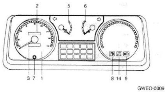


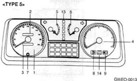


1 Speedometer
2 Odometer
3 Trip meter
4 Tachometer
5 Fuel gauge
6 Water temperature gauge
7 Trip meter reset button
8 Low fuel warning lamp
9 High beam indication lamp
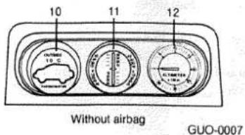
10 Thermometer
11 Inclinometer*
12 Altimeter*
13 A/T position indicator lamp*
14 Air bag warning lamp*
Speedometer

The speedometer indicates the vehicle's speed in kilometers per hour (km/h) or miles per hour (mph).
Odometer
The odometer indicates the total distance the vehicle has travelled.
Tripmeter and reset button
The tripmeter indicates the distance travelled during a particular trip or period. Press the reset button to return the tripmeter indication to zero.
Tachometer
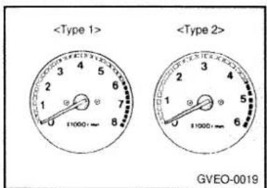
The tachometer indicates the engine speed (r/min). The tachometer can help you obtain more economical driving and also warns you of excessive engine speeds. During travel, watch the tachometer to be sure that the engine speed indication does not rise to the red zone (range of the excessive engine rpm).
Fuel gauge

The fuel gauge indicates the fuel level in the fuel tank.
1 - Full
2 - Empty
Water temperature gauge

natural_image
Simple line drawing of a curved mechanical component with a circular body and a lever, labeled GVEO-0021 (no text or symbols on the diagram itself)The water temperature gauge indicates the engine coolant temperature when the ignition switch is at the "ON" position. If the indication needle enters the red zone while the engine is running, it probably indicates that the engine is overheated. While driving, care should always be taken to maintain the normal operating temperature.
Thermometer*

The thermometer displays the temperature outside the vehicle when the ignition switch is at "ACC" or "ON".
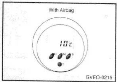
How T button works :
T - To change from clock to thermometer, push this button more than 1 second. (Vehicles with airbag system.) To convert °F←°C push this button less than 1 second.
To change from thermometer to clock, push this button more than 2 seconds.
NOTE
- The external temperature displayed may differ from the actual temperature on account of surrounding conditions, driving conditions, etc.
- Temperature outside the vehicle that are below -30°C(-22°F) or over 70°C(158°F) will result in an error message being displayed (-E°C or -E°F, E°C or E°F).
If an error message is displayed even though the actual temperature is within the range of -30ircC(-22ircF) to 70ircC(158ircF) , contact a GAL-LOPER dealer for inspection of the thermometer's thermo sensor.
Inclinometer*

This meter indicates the inclination angle of the vehicle, both front-to-rear and side-to-side
Examples
1 - Side to side inclination (Right inclination of 15irc )

2 - Front-to-rear inclination (Rear inclination of 20°)

3 - Front-to-rear and side-to-side inclination (Front inclination of 10°)
Altimeter*

Before driving the vehicle, set the pointer to 0 on the dial by turning the adjusting knob. The meter will indicate the height at the destination.
Indication and warning lamps
Diesel-powered vehicles

flowchart
graph TD
    A["1"] --> B["O/D OFF"]
    C["2"] --> D["Car Icon"]
    E["3"] --> F["Car Icon"]
    G["4"] --> H["Camera Icon"]
    I["5"] --> J["Motor Icon"]
    K["6"] --> L["A/T TEMP Icon"]
    M["7"] --> N["Car Icon"]
    O["8"] --> P["Car Icon"]
    Q["9"] --> R["Motor Icon"]
    S["10"] --> T["Car Icon"]
    U["11"] --> V["A/T TEMP Icon"]
    W["12"] --> X["Car Icon"]
GVSO-0001
Gasoline-powered vehicles

flowchart
graph TD
    A["1"] --> B["O/D OFF"]
    C["2"] --> D["Check Engine"]
    E["3"] --> F["Vehicle"]
    G["4"] --> H["Check Engine"]
    I["5"] --> J["Check Engine"]
    K["6"] --> L["Check Engine"]
    M["7"] --> N["Check Engine"]
    O["8"] --> P["Check Engine"]
    Q["11"] --> R["A/T TEMP"]
    S["12"] --> T["A/T TEMP"]
    U["13"] --> V["A/T TEMP"]
GVSO-0002
1 ABS warning lamp*
2 Overdrive off indication lamp*
3 Back door ajar warning lamp(Kick-up roof only)
4 Charge warning lamp
5 Brake warning lamp
6 Oil pressure warning lamp
7 Seat belt warning lamp
8 Door ajar warning lamp
9 Diesel preheat indication lamp
10 Fuel filter warning lamp
11 A/T oil temperature warning lamp*
12 4WD indication lamp
13 Self-diagnosis check lamp
14 Brake vacuum pressure warning lamp
Turn signal indication lamps

These indication lamps blink on and off when a turn signal lamp is blinking. If the blinking is too fast, the cause may be faulty connection of the turn signal or a failure of the bulb of the turn signal lamp.
High-beam indication lamp

This indication lamp illuminates when the high beams are on.
4WD indication lamp

The lamp will illuminate when the transfer case shift lever is shifted to the four wheel driving position (either the "4H" or the "4L" position) when the key is at the "ON" position.
Self-diagnosis check lamp (gasoline-powered vehicle only)
CHECK ENGINE
This lamp illuminates when the ignition switch is turned to the "ON" position, and then it will go out in a few seconds. If it lights up while the engine is running, there is a problem in the emission control system. Contact the nearest GALLOPER dealer.
Oil pressure warning lamp

This lamp illuminates when the ignition switch is set to the "ON" position and goes off after the engine has started. If it lights up while the engine is running, the engine must be stopped at once. Contact the nearest GAL-LOPER dealer.
Brake warning lamp
BRAKE
GVEO-0210
With the ignition switch at the "ON" position, the brake warning lamp illuminates under the following conditions:
(1) When the parking brake lever has been pulled.
(2) When the brake fluid level in the reservoir falls to a low level.
(3) If a malfunction develops in the brake servosystem.
( If the lamp should illuminate, it indicates that the effectiveness of the brakes has deteriorated and that the brake pedal should be depressed with more force than usual.)
If the lamp remains lit and will not go out, stop the vehicle immediately and contact the nearest GALLOPER dealer.
Charge warning lamp
GVEO-0207
This lamp illuminates when the ignition switch is set to the "ON" position and goes off after the engine has started. If it lights up while the engine is running, there is a problem in the charging system. Check to see if the v-belt is broken, and then contact the nearest GALLOPER dealer.
Door ajar warning lamp
29
This lamp illuminates when the front or rear door is opened or incompletely closed.
Diesel preheat indication lamp
29
The indication lamp illuminates amber when the ignition switch is placed at the "ON" position. As the glow plug becomes hot, the lamp turns off and the engine can be started.
Fuel filter warning lamp (diesel-powered vehicles only)

29
This lamp illuminates when the ignition switch is set to the "ON" position and goes off after the engine has started. If it lights up while the engine is running, it indicates that water has accumulated inside the fuel filter; if this happens, remove the water from the fuel filter.
Low fuel warning lamp
This lamp illuminates when the fuel level in the fuel tank falls to a low level.
- Fuel remainder when warning lamp lights: Long body type : approximately 15 liters Short body type : approximately 11 liters If it illuminates, fuel should be added soon.
Air bag warning lamp

Air bag warning lamp comes on and flashes 6 times after the ignition key is turned to the "on" position or after the engine is started, and then it will go out.
A/T (Automatic transmission) oil temperature warning lamp*
A/T TEMP
The A/T oil temperature warning lamp comes on when the A/T fluid temperature becomes abnormally high. When the lamp comes on, reduce the engine revolution and move the vehicle to a safe area. Then, set the selector lever to "P" position and idle the engine until the warning lamp goes off. When the warning lamp goes off, the vehicle can run as before. If the warning lamp does not go off, please have your vehicle inspected at a GALLOPER dealer.
Overdrive off indication lamp*
O/D OFF
The lamp will light up when the overdrive switch is off.
ABS warning lamp\*
ABS

GVEO-0211
The ABS warning lamp should illuminate when the ignition switch is set to "ON", and should go off in approximate 1 second.
If the warning lamp is kept on, it indicates that the ABS is not functioning and that only the standard brake system is in operation.(Of course the standard brake system will still function normally.)
Brake vacuum pressure warning lamp
(diesel-powered vehicles only)

GVEO-0025
This lamp illuminates when the vacuum pressure in the brake booster falls to a low level. If the lamp should illuminate, it indicates that the effectiveness of the brakes has deteriorated and that the brake pedal should be depressed with more force than usual.
If the lamp remains lit and will not go out, stop the vehicle immediately and contact the nearest GALLOPER dealer.
Seat belt warning lamp

GVEO-0026
This lamp illuminates when the ignition is switched on, then goes out 6 seconds later.
Switches
Light switch
Turn/lane change signal switch
Dipper switch
Passing switch
Windscreen wiper and washer switch
Headlight washer switch*
Rear window wiper and washer switch
Rheostat (meter illumination control)
Hazard warning flasher switch
Rear window demister switch
Cargo lamp
Room lamp
Front fog lamp switch*
Rear fog lamp switch*
Headlight leveling device *
Light switch

Rotate the switch to turn on the lights.
1 - Lights off
2 - Position, tail, license-plate, and instrument panel lamps on
3 - Headlights on
[ For Sweden, Iceland, Finland, Norway, Denmark]
When the ignition key is at the "ON" position and the light switch is set to the "OFF" position, the low beam of the headlights, tails, etc., will illuminate (Daytime Running Light).
Turn/lane change signal switch

natural_image
Illustration of a hand holding a tool with directional arrows indicating motion (no text or symbols)The turn signal lamps flash when the switch is operated (with the ignition switch at the "ON" position).
Dipper switch
The beam changes from high to low (or low to high) each time the lever is pulled. While the high beam is on, the high beam indication lamp will also illuminate.
Passing switch
The headlights will go on when the lever is pulled and will go off when it is released.
Windscreen wiper and washer switch

The windscreen wiper and washer switch can be operated by moving the switch lever with the ignition switch at the "ON" or "ACC" position.
Windscreen wiper
1 - Off
2 - Intermittent operation
3 - Slow
4 - Fast
On vehicles with the variable intermittent type, the intermittent intervals are adjustable from 3 to 12 seconds by turning the adjusting knob.
Turn the knob toward you to extend the intermittent intervals.
Headlight washer switch* (If installed)
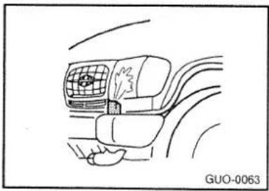
natural_image
Line drawing of a car interior showing the front seat and dashboard (no text or symbols)The headlight washer switch can be operated with the ignition switch at the "ON" position and the light switch at the on position. Push the button once and the washer fluid will be sprayed on to the headlights for about 0.5 second.
NOTE
Check the headlight washers periodically to confirm that the washer fluid is being sprayed properly onto the headlight lenses.
NOTE
(1) Before operating the wipers in cold weather, check to be sure that the wiper blades are not frozen to the windscreen. Attempting to operate the wipers while the blades are frozen to the windscreen could cause the motor to burn out.
(2) If the wipers stop during operation because of ice or some other obstruction on the windscreen, the wiper motor could burn out even if the wiper switch is turned off. If this occurs, promptly stop the vehicle, turn off the ignition, and clean the windscreen to allow proper wiper operation.
(3) Do not use the wipers when the windscreen is dry: doing so could scratch the windscreen and wear the blades prematurely.
Windscreen washer

The washer fluid will be sprayed onto the windscreen.
For vehicles equipped with intermittent wipers, the wipers operate automatically while the washer fluid is being sprayed. Avoid using the washer continuously for more than 20 seconds.
Do not operate the washer when the fluid reservoir is empty.
Rear window wiper and washer switch

natural_image
Illustration showing a hand inserting a plug into a socket, with no text or symbols present.The rear window wiper and washer switch can be operated with the ignition switch at the "ON" position. Push the switch to operate the rear window wiper or spray the washer fluid.
NOTE
(1) Before operating the wiper in cold weather, check to be sure that the wiper blade is not frozen to the rear window. Attempting to operate the wiper while the blade is frozen to the rear window could cause the motor to burn out.
(2) If the wiper stops during operation because of ice or some other obstruction on the rear window, the wiper motor could burn out even if the wiper switch is turned off. If this occurs, promptly stop the vehicle, turn off the ignition, and clean the rear window to allow proper wiper operation.
(3) Do not use the wiper when the rear window is dry; doing so could scratch the rear window and wear the blade prematurely.
Rear window washer
The washer will be sprayed onto the rear window while the switch is being pushed. Avoid using the washer continuously for more than 20 seconds.
Do not operate the washer when the fluid reservoir is empty.
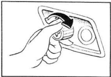
Rheostat (meter illumination control)
natural_image
Hand holding a wrench to press a device (no text or symbols visible)The rheostat can be adjusted while the light switch is on. Turn the knob to adjust the meter illumination to the desired brightness.
Hazard warning flasher switch

The hazard warning lamps can always be operated, regardless of the position of the ignition key.
When this switch is operated, all turn signal lamps flash continuously, as do the turn signal indication lamps.
Limit the operation time to less than an hour, otherwise the battery will be discharged.
Rear window demister switch
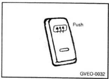
The rear window demister is turned on by pushing in on the switch.
The indication lamp will illuminate while the demister is on.
Push it again to turn it off.
NOTE
(1) The engine must be running for the rear window demister to operate. Be sure to turn the demister off immediately after the window is clear.
(2) When cleaning the inside of the rear window, use a soft cloth and wipe gently along the heater wires, being careful not to damage the wires.
Cargo lamp

natural_image
Hand holding a small object with two labeled parts, against a striped background (no text or symbols)1 - The lamp goes out.
2 - The lamp illuminates.
Room lamp

The room lamp can be operated by moving the lens itself to the left or right or pushing the button.

1 - Push the button to turn on the lamp (left side).
Push it again to turn it off.
2 - The lamp illuminates when a door is opened and goes out when it is closed.
3 - Push the button to turn on the lamp (right side).
Push it again to turn it off.
Front fog lamp switch\* (If installed)

natural_image
Simple line drawing of a rectangular object with a label '50' and a horizontal bar, no readable text or symbols beyond the label.The front log lamp can operate when the headlight beam is on.
Rear fog lamp switch * (If installed)
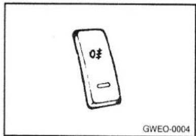
The rear fog lamp can operate when the headlight beam is on.
Push the switch to turn on the lamp. Push it again to turn it off.
The indication lamp will light up while the rear fog lamp is on.
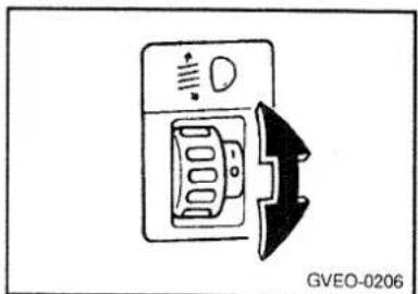
Headlight leveling device system * (If installed)
natural_image
Diagram of a device with a speaker and directional arrow, no readable text or symbols presentTo adjust the headlight beam level according to the number of the passengers and the loading weight in the luggage area, turn the beam leveling switch.
The higher the number of the switch position, the lower the headlight beam level.
Always keep the headlight beam at the proper leveling position, or headlights may dazzle other road users.
Listed below are the examples of proper switch settings.
For loading conditions other than those listed below, adjust the switch position so that the beam level may be the nearest as the condition obtained according to the list.
| Loading condition | SW position(SWB/LWB-5seats/LWB-7 seats)/LWB-9seats/VAN |
| Driver only | 0/0/0/0/0 |
| Driver + front pas-senger | 0/0/0(except VAN) |
| Driver + front passen-ger + rear passenger in luggage boot | 1/1 (only LWB 7seats/LWB 9seats) |
| Full passengers (including driver) | 1/0/1/1(except VAN) |
| Full passengers(including driver) + full trunk loading | 2/1/2/1(except VAN) |
| Driver + full trunk loading | 2/2/3/2/1 |
MEMO
Key-locking and unlocking
Doors
Electric door locks
Bonnet
Backdoor
Electric window control
Sliding window
Electronic immobilizer*
Doors
Operation from outside the vehicle

1 - Insert or remove the key
2 - Lock
3 - Unlock
Operation from inside the vehicle
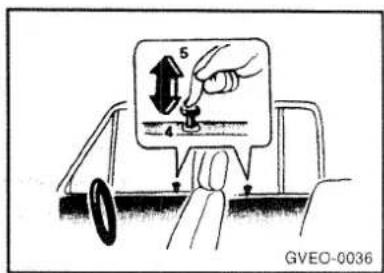
4 - Lock
5 - Unlock
Pull the inside handle toward you to open the door.
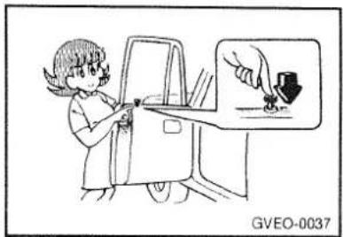
To lock the front doors without a key
natural_image
Illustration of a child using a car to interact with a hand holding a small object, no text or symbols presentSet the inside lock button to the locked position. Be careful not to lock the doors while the key is inside the vehicle.
To lock the rear doors
Set the inside lock button to the locked position and close the door.
Electric door locks

By using either the inside lock button or the key to lock or unlock the front driver's door, all of the doors can be simultaneously locked or unlocked.
1 - Lock
2 - Unlock
Bonnet
To open

natural_image
Illustration of a person inside a car with a magnifying glass, showing a sleeping person and a vehicle (no text or symbols)Pull the release lever toward you to unlock the bonnet.

natural_image
Illustration of a person pushing a car with an upward arrow (no text or symbols)Raise the bonnet while pressing the safety lock.
natural_image
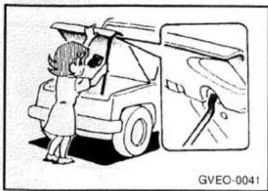
Cartoon illustration of a person loading a truck into a container with a magnified inset showing a hand near the vehicle (no text or symbols)Support the bonnet by inserting the support bar in its slot.
To close
Unlatch the support bar. Then lower and drop the bonnet. Make sure the bonnet is firmly locked in place.
Backdoor
Operation from outside the vehicle

1 - Insert or remove the key.
2 - Lock
3 - Unlock

natural_image
Hand placing a rectangular object into a door panel (no text or symbols visible)Pull the outside handle toward you to open the backdoor.
CAUTION
If the back door is opened at night, the tail lamp will be concealed by the door, so take some measure to assure that the vehicle can be seen by vehicles approaching from behind.
Operation from inside the vehicle

4 - Lock
5 - Unlock
Pull the inside handle toward you to open the back door.
To lock the backdoor without a key
Set the inside lock button to the locked position, and close the backdoor.
Be careful not to lock the backdoor while the key is inside the vehicle.
Electric window control
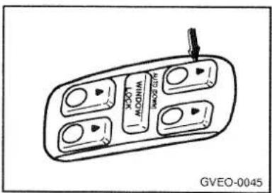
The electric window control can be operated with the ignition switch at the "ON" position.
Driver's switches
The driver's switches can be used to operate all door windows. A window can be opened or closed by pressing the corresponding switch.
Passenger's switches
The passenger's switches can be used to operate the corresponding passenger's door windows.

CAUTION
(1) Be careful that head or hands are not trapped by a closing window.
(2) To prevent injury, do not allow children to play with window control switches. When children are in the vehicle, make sure the window control lock switch is in the locked position.
(3) If a child (or other person who might not be capable of safe operation of the electrical window switches) is to be left in the vehicle alone, always be sure to turn off the ignition and remove the key.
(4) Never try to operate a driver's switch and a passenger's switch in opposing directions at the same time; the window will stop, and cannot then be opened or closed.
Sliding window
To open
Slide the window glass rearward while pressing the lock knob.
To close
Slide the window glass all the way and it will automatically lock.
Electronic immobilizer \* (if installed)
The electronic immobilizer system is an anti-theft device, designed to prevent and deter automobile theft. It means that the engine can only be started with the car's own keys. In addition to the need for the key to match the lock mechanically, a special electronic component is integrated into the key.
NOTE
The electronic components integrated into the key could become damaged if treated violently, and be rendered useless. It will then no longer be possible to start the engine with a key damaged in this way.
Obtaining a new key :
Replacement keys are only available from an authorized GALLOPER dealer, which is obliged to check whether every person ordering such a key is authorized to do so. An authorized GALLOPER dealer is also able to block individual keys electronically (e.g. if lost) and restore them to use again. The engine cannot be started with a key that has been blocked.
Keys* (if electronic immobilizer installed)

- I.D. key
This key must be used first to register unique ID code in ICM. This key is not intended for everyday use.
- Master key
This key is for general use. It will open all locks on your vehicle.
CAUTION
Don't lose your ID key or forget the password. Always keep your ID key at the designated place where you know and record your password.
If you don't have both of password and ID key, you can not get additional keys any more.
ICM: Immobilizer Control Module
Interior equipment
Front seats
Second seat
Third seats
Make second and third seats into bed
Head restraints
Heated seats*
Seat belts
Supplemental restraint (airbag) system "SRS"*
Adjustment of steering wheel height
Sun visors
Cigarette lighter
Ashtrays
Accessory boxes
Digital clock
Luggage securing hooks

natural_image
Illustration of a child using a medical or surgical tool to interact with another person, showing a magnified view of the hand and foot (no text or symbols present)Front seats
Adjust the seats by operating the levers as indicated by the arrows to move the seats to the desired positions.
CAUTION
Never adjust the driver's seat while the vehicle is in motion.
1 - Adjustment forward or backward

2 - Adjustment of seatback angle
To get in and out of the rear seat (Short-wheel-based models)

natural_image
Mechanical assembly diagram showing a hand pressing a component with a black arrow indicating force direction (no text or symbols)1 - To get in

natural_image
Diagram of a hand holding a small black object labeled '2' connected to a mechanical bracket (no text or symbols present)2 - To get out
CAUTION
When returning the seatback to its original position, be careful not to get hands, legs, etc., caught in the seat.
Second seat
Adjustment of seat

Adjust the seat by operating the handle in the direction of arrows to move the seat to desired position.
1 - Adjustment of seatback angle
To get in and out of third seat

1 - To get in
2 - To get out

natural_image
Diagram of a car interior showing directional arrows and a circular object, labeled GVEO-0052 (no text or symbols on diagram itself)Fold down the side seatback by pulling the knob for the convenience of getting in or out of the third seat.
CAUTION
When passengers get in and out, they should watch their step carefully to avoid injuring themselves on the rear seat frame, springs, and other parts.
Folding the seat

Lower the head restraints all the way. Fold the seatback downward and forward by operating the knob.
NOTE
Before folding the seatback, be sure to lock the seat in the rearmost position.

natural_image
Illustration of a child using a tablet at a desk with an inset showing a hand pointing at a device (no text or symbols present)Lift up the handle for folding the seat and fold the entire seat upward and forward until it locks.
CAUTION
Do not fold down the second seat when the third seat is used, because the projections on the backside of the second seat may be injurious.
Unfolding the seat

natural_image
Illustration of a child using a seatbelt to lift a car (no text or symbols present)While pulling the lever on the left side of the rear seat towards you, fold the seat down, and then raise the seatback.
Third seats
Adjustment of seat

natural_image
Illustration of a child sitting on a chair holding a small object, with no visible text or symbols.Adjust the seats by operating the handles to move the seats to desired positions.
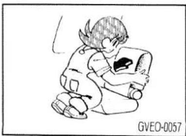
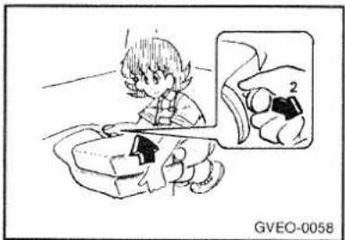
Folding the seats
natural_image
Simple line drawing of a person sitting and holding an object, no text or symbols present1 - Press the lever and fold the seatback forward and down until it locks.
natural_image
Illustration of a child using a tablet to interact with a hand, with an inset showing a hand holding a device (no text or symbols present)2 - While pulling back on the knob, fold the entire seat upward.
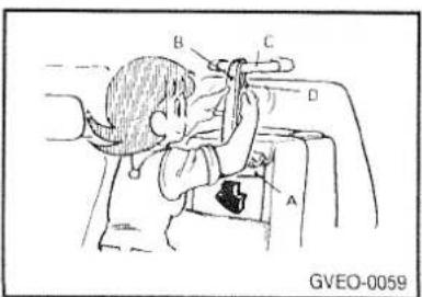
3 - Fold the foot (A) and hook the belt (B) onto the assist handle (C). Lower the belt buckle (D) to tighten the belt and secure the seat.
Unfolding the seats
- Raise the belt buckle to loosen the belt.
- Unhook the belt from the assist strap.
- Unfold the seat by reversing the procedure used to fold it.
CAUTION
When unfolding the seats, be sure to unfold the leg down far enough.
Third seats (Side facing seats)
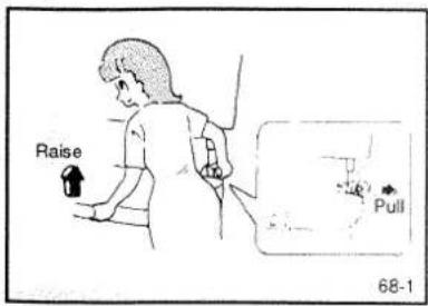
Folding the seats
Pull the knob as shown, and raise the seat cushion.
natural_image
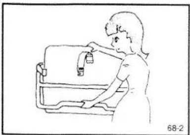
Line drawing of a person washing a kitchen sink with a faucet (no text or symbols)Fold the leg underneath.

Attach the belt to the hook on the seatback, and secure the seat cushion.
Make second and third seats into bed

natural_image
Diagram of a car interior showing steering wheel and gear (no text or symbols)Remove the head restraints of the second seat. Recline the seatback of second seat all the way back by following procedure:
- Operate either the rear seat lever or pedal to slide the rear seat forward.
- Pull the side seatback knob and fold down the side seatback.
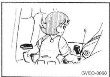
- Pull the second seat reclining lever (A) and fold the seatback down all the way. While pushing the second seat toward the rear, raise the lever (B) to lock the second seat.

natural_image
Diagram of a person using a device to interact with a car, showing a magnified inset of a small object labeled 'A' (no text or symbols on the diagram itself)CAUTION
Folding down the seatback all the way while the side seatback is still secured to it could damage the side seatback.
natural_image
Illustration of a child sitting in a car seat, wearing a vest and holding an object (no text or symbols visible)To return the seat to the original position; press the lever (B) down and move the seat backward until it is securely locked.
Do not operate lever (B) except when making a bed or returning the seat to the original position.
Recline the seatback of third seat all the way back.

natural_image
Line drawing of a child lying on the back of a vehicle, no text or symbols presentCAUTION
Do not walk around on top of the seats after they have been made into a bed. If you make a false step and your foot misses the seat, you could be injured; always move around carefully and step only in the middle of the seats.
For technical reasons, the vehicle should not be driven with bed.
Head restraints
Adjustment of the head restraints
Adjust the head restraints height so that the center of the restraints is as close as possible to the back of the head at eye level to reduce the chance of injury in the event of collision.
Removal of the head restraints

Front seats
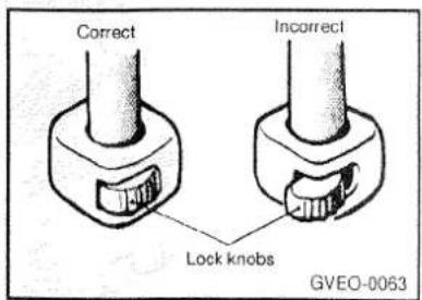
To remove the head restraints, press the lock knobs in the direction indicated by the arrows and pull up on the restraints. To remount the head restraints, first confirm that they are facing the correct direction, and then insert them into the seatback and push down until they lock.
Confirm that the lock knobs are correct as shown in the illustration, and also pull up on the head restraints to confirm that they do not come out of the seatback.
CAUTION
It is dangerous to drive without or badly adjusted head restraints installed; always have them correctly mounted when using the vehicle.
Rear seats

To remove the head restraints, press the height adjusting knobs in the direction indicated by the arrows and pull up on the restraints.
To remount the head restraints, first confirm that they are facing the correct direction and then insert them into the seatback and push down until they lock.
Confirm that the height adjusting knobs are correct as shown in the illustration, and also pull on the head restraints to confirm that they do not come out of the seatback.
CAUTION
It is dangerous to drive without or badly adjusted head restraints installed; always have them correctly mounted when using the vehicle.
Heated seats\*
The heated seats can be operated with the ignition switch in the "ON" position.

natural_image
Simple line drawing of a toilet with a checkmark and two buttons, no text or symbols present.Seat belts
To protect you and your passengers in the event of an accident, it is most important that the seat belts be worn correctly when you drive.
3-point seat belts
It is not necessary to adjust: the belt length. The belt becomes looser and tighter as the wearer moves, but is locked automatically to hold the wearer if a strong impact occurs.
To fasten the belt
Insert the plate into the buckle until a "click" is heard.


CAUTION
(1) Always position the lap portion of belt as low on the hipbone as possible.
(2) The seat belts must not be twisted when worn.
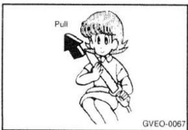
Adjust any looseness by pulling the belt slightly.
To unfasten the belt

Press the button in the buckle while holding the plate.
NOTE
The belt will rewind automatically, hold the plate and let it rewind gradually.

CAUTION
(1) When the tongue plate is connected to the buckle, do not mix up the left, right or center the buckle.
Use the proper buckle as shown in the figure.
(2) Do not fold down the side seatback of the second seat when the second seat belt is used, because the seat belt will be interfered with the side seatback and will not operate properly.

Handling seat belts
- When driving with children, they should be seated in the rear seat, and wear lap belts. For an infant, a child safety seat should be used.
The regulations concerning driving with children in the front seat may differ from country to country. It is recommended that you obey the pertinent regulations.
- Pregnant woman should use 3-point type seat belt whenever possible. The lap belt should be worn as low as the hips, but not across the waist.
natural_image
Cartoon illustration of a person in a car with head turned, wearing a helmet and gear (no text or symbols)CAUTION
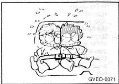
- One seat belt should be used by only one person. Doing otherwise can be dangerous.

natural_image
Simple line drawing of a child sitting on a car seat, no text or symbols presentSeat belts inspection
- Check the belt for cuts, worn of frayed webbing and for cracked or deformed metallic parts. Replace the belt if defective.
- A dirty belt should be cleaned with neutral detergent in warm water. After rinsing in water, let it dry in the shade.
Do not attempt to bleach or re-dye the belts, because this affects their characteristics.
- Seat belts worn at the time of an accident should not be reused even if they appear flawless, because deteriorated belts cannot withstand another accident. Be sure to replace the belts and mounting bolts with new ones.
Supplemental restraint (airbag) system "SRS" \* (if installed)

Your vehicle is equipped with a Supplemental Restraint (Airbag) System.
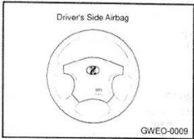
The indications of the system's presence are the letter "SRS 40" embossed on the airbag pad cover in the steering wheel.
The SRS consists of airbag installed under the pad covers in the center of the steering wheel. The purpose of the SRS is to provide the vehicle's driver with additional restraint than that offered by the seat-belt system alone, in case of a frontal impact of sufficient severity.
NOTE
Be sure to read information about the SRS on the labels provided on the backside of the sun visor.
WARNING
(1) The SRS is designed to work with, and be supplemental to, the driver's three point seat belt system and is not a substitute for it. Therefore, your seat belts must be worn at all times while the vehicle is in motion. In addition, the airbag deploys only in certain frontal impact conditions severe enough to likely cause significant injury to the vehicle occupants.
(2) The SRS is designed to deploy the airbag only when an impact is sufficiently severe and will not deploy in side, rear of rollover impacts. Additionally, the airbag will only deploy once. Thus, seat belts must be worn at all times.
(3) For maximum safety protection in all types of crashes, all occupants including the driver should always wear their seat belts whether or not an airbag is also provided at their seating position to minimize the risk of severe injury or death in the event of a crash. Do not sit or lean unnecessarily close to the airbag while the vehicle is in motion.
(4) The SRS airbag system must deploy very rapidly to provide protection in a crash. If an occupant is out of position because of not wearing seat belt, the airbag may forcefully contact the occupant causing serious or fatal injuries.
SRS Component and Functions\*

natural_image
Medical illustration showing a person in a car with a medical device inserted, no text or symbols presentThe SRS consists of the following component:
- Driver's side Airbag Module
- SRS Service Reminder Indicator (SRI)
- SRS Control Unit (SRSCU)
The SRSCU continually monitors all elements while the ignition is "ON" to determine if a frontal or near-frontal impact is severe enough to require airbag deployment.
The SRS service reminder indicator(SRI) on the instrument panel will blink 6 items after the ignition key is turned to the "ON" position or after the engine is started, and then the SRI should go out.
The airbag module is located in the center of the steering wheel.
When the SRSCU detects a considerable impact to the front of the vehicle, it will automatically deploy the airbag.
Upon deployment, tear seams molded directly into the pad covers will seperate under pressure from the expansion of the airbag. Further opening of the covers then allows full inflation of the airbag.
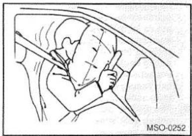
A fully inflated airbag in combination with a properly worn seat belt slows the driver's forward motion, thus reducing the risk of head of chest injury.
After complete inflation, the airbag immediately starts deflating, enabling the driver to maintain forward visibility.
SRS care
The service-work of the SRS components are permitted by only an authorized GALLOPERdealer and so there are no parts you can safely service by yourself. The entire SRS system must be inspected by an authorized GALLOPERdealer 10 years after the date that the vehicle was manufactured.
Any work on the SRS system, such as removing, installing, repairing, or any work on the steering wheel must be performed by a
authorized GALLOPERdealer. Improper handling og the SRS system may result in serious personal injury.
WARNING
(1) Modification to SRS components or wiring, including the addition of any kind of badges to the pad covers or modifications to the body structure, can adversely affect SRS performance and lead to possible injury.
(2) For cleaning the airbag pad covers, use only a soft, dry cloth or one which has been moistened with plain water Solvents or cleaners could adversely affect the airbag covers and proper deployment of the system.
(3) No objects should be placed over or near the airbag module on the steering wheel, because any such object could cause harm if the vehicle is in a crash severe enough to cause the airbag to inflate.
(4) If the airbag inflate, they must be replaced by an authorized GALLOPER dealer.
(5) If components of the airbag system must be discarded, or if the vehicle must be scrapped, certain safety precautions must be observed. Your GALLOPER dealer knows these precautions and can give you the necessary information. Failure to follow
these precautions and procedures could increase the risk of personal injury.
(6) If you sell your vehicle, be sure to inform the new owner of these important points and make certain that this manual is transferred to the new owner.
(7) If your car was flooded and has soaked carpeting or water on flooring, you shouldn't try to start engine; have the car towed to authorized GALLOPER dealer.
Your vehicle is equipped with a Supplemental Restraint (Airbag) System.
The indications of the system's presence are the letter "SRS AI" embossed on the airbag pad cover in the steering wheel.
The SRS consists of airbag installed under the pad covers in the center of the steering wheel. The purpose of the SRS is to provide the vehicle's driver with additional restraint than that offered by the seat-belt system alone, in case of a frontal impact of sufficient severity.
NOTE
Be sure to read information about the SRS on the labels provided on the backside of the sun visor.
WARNING
(1) The SRS is designed to work with, and be supplemental to, the driver's three point seat belt system and is not a substitute for it. Therefore, your seat belts must be worn at all times while the vehicle is in motion. In addition, the airbag deploys only in certain frontal impact conditions severe enough to likely cause significant injury to the vehicle occupants.
(2) The SRS is designed to deploy the airbag only when an impact is sufficiently severe and will not deploy in side, rear of rollover impacts. Additionally, the airbag will only deploy once. Thus, seat belts must be worn at all times.
(3) For maximum safety protection in all types of crashes, all occupants including the driver should always wear their seat belts whether or not an airbag is also provided at their seating position to minimize the risk of severe injury or death in the event of a crash. Do not sit or lean unnecessarily close to the airbag while the vehicle is in motion.
(4) The SRS airbag system must deploy very rapidly to provide protection in a crash. If an occupant is out of position because of not wearing seat belt, the airbag may forcefully contact the occupant causing serious or fatal injuries.
SRS Component and Functions\*
natural_image
Medical illustration showing a patient undergoing a surgical procedure in a car (no text or symbols present)The SRS consists of the following component:
- Driver's side Airbag Module
- SRS Service Reminder Indicator (SRI)
- SRS Control Unit (SRSCU)
The airbag module is located in the center of the steering wheel.
When the SRSCU detects a considerable impact to the front of the vehicle, it will automatically deploy the airbag.
Upon deployment, tear seams molded directly into the pad covers will seperate under pressure from the expansion of the airbag. Further opening of the covers then allows full inflation of the airbag.
A fully inflated airbag in combination with a
properly worn seat belt slows the driver's forward motion, thus reducing the risk of head of chest injury.
After complete inflation, the airbag immediately starts deflating, enabling the driver to maintain forward visibility.
WARNING
(1) Never to try to fix the object (ornament materials, stickers etc.) to the cushioned covering in the steering wheel. It's possible thereby to hurt the driver when the airbag is pumped up.
(2) Never to try to fix the object to the windscreen. It's possible that the object could hinder the remove of airbag or be thrown towards passengers and they could be hruted thereby so seriously.
(3) Some components of airbag system get heated by the pumping-up of airbag system. Don't touch therefore these components after the pumping-up.
SRS warning lamp\*

The SRS warning lamp on the instrument panel will blink for about 6 seconds after the ignition key is turned to the "ON" position or after the engine is started, and then the SRS warning lamp should go out.
WARNING
Thr following cases means that there is problem with the system. Immediately have it checked by an authorized GAL-LOPER dealer.
- When the warning lamp stays on after turning the ignition switch on.
- When the warning lamp goes on while driving.
- When the warning lamp does not light up after the ignition key is turned to the "ON" position.
SRS care
The service-work of the SRS components are permitted by only an authorized GALLOPERdealer and so there are no parts you can safely service by yourself. The entire SRS system must be inspected by an authorized GALLOPERdealer 10 years after the date that the vehicle was manufactured.
Any work on the SRS system, such as removing, installing, repairing, or any work on the steering wheel must be performed by a authorized GALLOPERdealer. Improper handling og the SRS system may result in serious personal injury.
WARNING
(1) Modification to SRS components or wiring, including the addition of any kind of badges to the pad covers or modifications to the body structure, can adversely affect SRS performance and lead to possible injury.
(2) For cleaning the airbag pad covers, use only a soft, dry cloth or one which has been moistened with plain water Solvents or cleaners could adversely affect the airbag covers and proper deployment of the system.
(3) No objects should be placed over or near the airbag modules on the steering wheel, because any such object
could cause harm if the vehicle is in a crash severe enough to cause the airbag to inflate.
(4) If the aribag inflate, they must be replaced by an authorized GALLOPER dealer.
(5) If components of the airbag system must be discarded, or if the vehicle must be scrapped, certain safety precautions must be observed, your GALLOPER dealer knows these precautions and can give you the necessary information. Failure to follow these precautions and procedures could increase the risk of personal injury.
(6) If you sell your vehicle, be sure to infrom the new owner of these important points and make certain the this manual is transferred to the new owner.
(7) If your vehicle has to be broken, you should bring it to an authorized GAL-LOPER dealer in order to deactivate the SRS.
(8) If your car was flooded and has soaked carpeting or water on flooring, you shouldn't try to start engine; have the car towed to authorized GALLOPER dealer.
Adjustment of steering wheel height

natural_image
Illustration of a person receiving a medical or therapeutic aid from another person, labeled GVEO-0073 (no text on diagram)The height of steering wheel in your vehicle can be adjusted to give you the best seat position in driving. While supporting the steering wheel with one hand, pull the lever upward and then adjust the steering wheel to the most suitable position.
After the adjustment is completed, the lever will automatically return when it is released, but the lever should be moved even further downward to secure it completely.
If the lever does not return automatically when released, or stops part way, it can be made to return by shaking the steering wheel up and down.
WARNING
Do not adjust the height of steering wheel while you are driving the vehicle.
Sun visors
natural_image
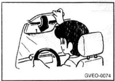
Illustration of a person driving a car, showing the dashboard and seat (no text or symbols)1 - To eliminate front glare
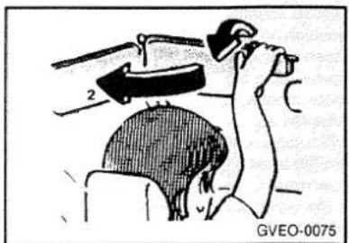
natural_image
Medical illustration showing a surgical procedure on a patient's head (no text or symbols present)2 - To eliminate side glare
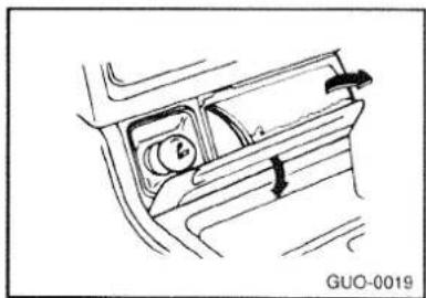
Cigarette lighter

The cigarette lighter can be used while the ignition switch is at either "ON" or "ACC".
1 - Push all the way in.
The lighter will automatically return to its original position with a "click" when ready. Pull it out for use.
CAUTION
- Do not touch heating element or lighter housing. Hold at the knob only.
- Something is wrong with the cigarette lighter if it does not pop back out within approximately 30 seconds of being pushed in. Leaving the cigarette lighter pushed in for an extended period could cause a fire. If it does not pop out by itself, pull it out and have the problem corrected at a GALLOPER dealer.
Ashtrays
Front ashtray
natural_image
Line drawing of a car interior showing the dashboard and side panel (no text or symbols)The ashtray is located on the front main console.
The front ashtray may be opened by pulling out by its top edge.
To remove the ashtray to empty or clean it, pull it all the way out.
Rear ashtrays

natural_image
Line drawing of a hand holding a small object, no text or symbols presentPull the ashtray downward to open. To remove the ashtray, pull it out while pressing the stubber.
Accessory boxes

natural_image
Line drawing of a car interior showing seats and dashboard (no text or symbols)Various small articles can be kept in here.
1 - Glove box
Glove box
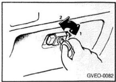
1 - To lock *
2 - To unlock *
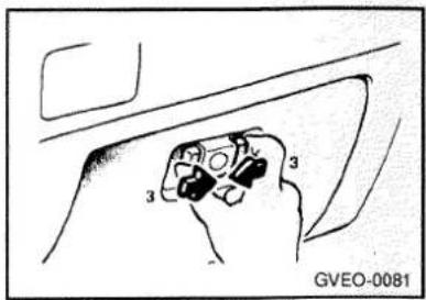
3 - To open, push both buttons
Digital clock

How each button works
H - To adjust the hour, push this button.
M - To adjust minutes, push this button.
R - To clear away minutes display in order to set the correct time, push this button.
Example
10:30\~11:29 ...... changes to 11:00
11:30\~12:29 ...... changes to 12:00

T - To change from thermometer to clock, push this button.
(Vehicles with airbag system)
NOTE
If the battery cables are disconnected during repairs or for any other reason, reset the clock to the correct time after the cables are reconnected.
Luggage securing hooks

natural_image
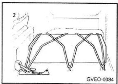
Technical line drawing of a mechanical component with no visible text or symbolsThere are four hooks on the floor of the luggage compartment for use in securing luggage.
1 - For small items
natural_image
Technical line drawing of a structural frame with truss elements, no visible text or symbols2 - For large items Fold down the rear seat. The luggage can be secured more firmly if the seat bracket holes are also used.
MEMO
For pleasant driving
Heating and ventilation
Air conditioning operation *
Rear air conditioner *
Rear heater *
Ventilators
Radio & Cassette tape player
HEATING AND VENTILATION
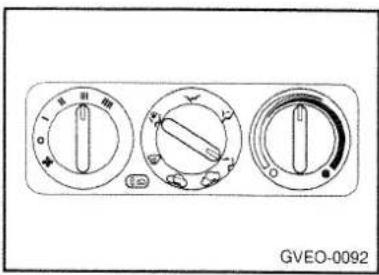
Rotary Type

This model has four controls for the heating and cooling system. They are :
- Fan speed control
- Air flow control
- Temperature control
- Air intake control
FAN SPEED CONTROL (BLOWER CONTROL)
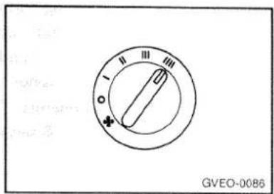
This is used turn the blower fan on and off, to select the fan speed.
The blower fan speed, and therefore the volume of air delivered from the system, may be controlled manually by setting the blower control between the "I" and "III" position.
AIR INTAKE CONTROL

This is used to select fresh outside air or recirculation inside air.
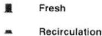
With the "fresh" mode selected, air enters the vehicle from outside and is heated or cooled according to the other functions selected.
With the "recirculation" mode selected, air from within the passenger compartment is drawn through the heating system and heated or cooled according to the other functions selected.
NOTE
It should be noted that prolonged operation of the heater in "recirculation" mode will give rise to misting of the windshield and side windows and the air within the passenger compartment becoming stale. In addition, prolonged use of the air conditioner with the "Recirculation" mode selected may result it in the air within the passenger compartment becoming excessively dry.
AIR FLOW CONTROL

This is used to direct the flow of air. Air can be directed to the floor, dashboard outlets, or windshield. Five symbols are used to represent Face, Bi-Level, Floor, Floor-Defrost and Defrost air position.
Face-Level
Selecting the "Face" mode will cause air to be discharged through the face level vents.
Bi-Level
Air is discharged through the face vents and the floor vents. This makes it possible to have cooler air from the dashboard vents and warmer air from the floor outlets at the same time.
√ Floor-Level
Air is discharged through the floor vents.
Floor-Defrost Level
Air is discharged through the windshield defrost vents and the floor vents.
Defrost-Level
Air is discharged through the windshield defrost vents.
TEMPERATURE CONTROL
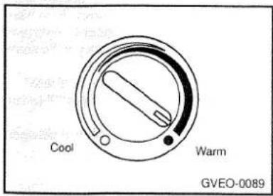
This is used to turn the heater on and off and to select the degree of heating desired.
HEATING CONTROLS
For normal heater operation, move the air intake control to the "Fresh" position and the air flow control to "Floor".
For faster heating, the air intake control should be in the "Recirculation".
If the windows fog up, move the air flow control to the "Def"(defroster) position and the air intake control to "Fresh"
For maximum heat, move the temperature control to "Warm"
BI-LEVEL HEATING
Your vehicle is equipped with bi-level heating controls. This makes it possible to have cooler air from the dashboard vents and warmer air from the floor outlets at the same time. To use this feature.
o Set the air intake control to "Fresh".
o Set the air flow control at the "Bi-Level" position.
o Set the temperature control between "Cool" and "Warm"
VENTILATION
To operate the ventilation system:
o Set the air intake control on "Fresh".
To direct all intake air to the dashboard vents, set the air flow control to "Face".
o Adjust the fan speed control to the desired speed.
o Set the temperature control between "Cool" and "Warm".
DEFROSTING/DEFOGGING

To use the heating/ventilation system to defrost or defog the windshield:
o Set the air intake control (4) to the "Fresh" position.
o Set the air distribution control (2) to the "Defrost" position.
o Set the temperature control (3) to a comfortably warm position.
o Set the fan speed control (1) to position "III" or "III".
o If vehicle is so equipped, turn on the A/C for increased defogging action.
NOTE
In high humidity areas the A/C can be used with the air intake in the "Recirculation" position for increased defogging action.
Operation Tips
To keep dust or unpleasant fumes from entering the car through the ventilation system, temporarily set the air intake control at "Recirculation". Be sure to return the control to "Fresh" when the irritation has passed to keep fresh air in the vehicle.
This will help keep the driver alert and comfortable.
Air for the heating/cooling system is drawn in through the grilles just ahead of the windshield. Care should be taken that these are not blocked by leaves, snow, ice or other obstructions.
AIR CONDITIONING OPERATION (If installed) COOLING

To use the air conditioner to cool interior:
o Set the side vent control to "OFF", to shut off outside air entry.
o Turn on the fan control switch.
Turn on the air conditioner switch by pushing in on the switch. The air conditioner indicator light should come on at the same time.
o Set the air intake control to "Fresh".
o Set the temperature control to "Cool" ("Cool" provides maximum cooling. The temperature may be moderated by the control toward "Warm".)
Adjust the fan control to the desired speed. For greater cooling, turn the fan control to one of the higher speeds or temporarily select the "Recirculation" position on the air intake control.
DEHUMIDIFIED HEATING
For dehumidified heating :
o Turn on the fan control switch.
o Turn on the air conditioner switch. The air conditioner indicator light should come on at the same time.
o Set the air intake control to "Fresh"
o Set the air flow control to "Face"
o Adjust the fan control to the desired speed. For more rapid action, set the fan at one of the higher speeds.
o Adjust the temperature control to provide the desired amount of warmth.
Notes concerning air conditioner operation
(1) Park the vehicle in the shade. Parking under the hot sun will make the car interior extremely hot, and it will require more time to cool the interior. If it is necessary to park in the sun, open the windows for the first few minutes of air conditioner operation to expel the hot air.
(2) Close the windows when the air conditioner is in use. The entry of outside air through open windows will reduce the cooling efficiency.
(3) When driving at low speeds, shift down to increase the engine rpm. If you must drive slowly in heavy traffic, shift to a lower gear to increase the engine rpm in order to obtain better efficiency and avoid overheating the engine.
(4) On steep grades, turn the air conditioner off to avoid the possibility of the engine overheating.
Operation hints
The air conditioner not only cools the air, but also dehumidifies it, thus offering greater comfort. Too much cooling is not good for the health. The air temperature should only be 5 to 6°C (9 to 11°F) lower than the out side air (to the extent that you feel somewhat cool).
During a long period of disuse
The air conditioner should be operated for at least five minutes each week, even in cold weather. This is to prevent poor lubrication of the compressor internal parts and to maintain the air conditioner in the best operating condition.
AUTOMATIC HEATING AND COOLING CONTROLS (If installed)

Your vehicle equipped with an automatic heating and cooling system controlled by you simply sets the desired temperature.
Semi-Automatic Temperature Control Features
BUTTON INTERLOCKS-Depressing a button in an interlock group will cause that button to latch and will unlatch the previously selected button.
"OFF BUTTON" - "Off button" turns complete system off.
DEFROST SAFETY OVERRIDES- For safety and defroster performance the fresh function is automatically controlled. (latching the defrost button will place the system in outside air.)
OVERRIDE INTERLOCKS-The Off and Defrost buttons automatically override the air conditioner and recirculation functions. When in override mode the air conditioner, recirculation, and outside air buttons cannot be latched.
INDICATORS-When the instrument panel illumination is on, the control selection can easily be determined by illuminated indicators on the levers and buttons.
DIAGNOSTIC LED(Light Emitted Diode)-Semi-automatic Temperature Control system diagnostics indicator for assembly plant end of line testing and dealer service testing.
TEMPERATURE AND BLOWER CONTROL LEVERS-For improved feel and mechanical indication of function the levers have light detents throughout the control lever range with, heavy detents for Full Air Conditioner, Full Heat, and Auto Blower.
- Off button
- Face button
- Bi-level button
- Floor button
- Floor-defrost button
-
Defrost button
-
Air conditioner button
- Recirculation button
- Fresh button
- Temperature control lever
- Diagnostic LED(light emitted diode)
- Blower control lever
BLOWER CONTROL
Automatic Blower Control

Automatic blower operation varies from low to high, blower speed based on set temperature, in car temperature, and ambient temperature. In floor mode the cold engine lock-out feature is active.
Manual Blower Control
Continuously variable manual blower speed override.
NOTE
If you want to operate rapid cooling or rapid heating, fix lever on "HI" position of manual mode.
AIR INTAKE CONTROL

This allows you to select fresh outside air or to recirculate inside air. Push the button in to get the proper interior condition.
NOTE
If any air flow control buttons are not pushed and also inside & outside buttons are not pushed, will be automatically operated in condition of fresh out side air. If "DEFROST" button pushed in, it is selected automatically fresh outside air without selecting air flow control buttons.
AIR FLOW CONTROL BUTTONS

This is used to turn the fan on and off and direct the flow of air. Air can be directed to the floor, dash board outlets or windshield. Six symbols are used to represent OFF, FACE, BI-LEVEL, FLOOR, FLOOR-DEFROST and DEFROST.
To use this automatic heating and cooling system, you first should push the one of these buttons except "OFF" button.
In case of "OFF" button pushed in, you can not push the air conditioner switch button and the air intake control buttons. This is a normal condition.
NOTE
If "OFF" button is pushed, be automatically operated in condition of inside air flow.
TEMPERATURE CONTROL
This is used to select the desired temperature. The numbers on the facia panel indicate the centigrade or fahrenheit temperature.
AIR CONDITIONER BUTTON
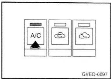
This is used to turn the air conditioner on and off. To turn the air conditioner on push the button, to turn it off push the button again.
NOTE
In case of "OFF" button pushed in, the air conditioner switch button does not engage. This is a normal condition.
HEATING CONTROLS

For normal heater operation, put the air intake control button to the "FRESH" position and put the mode door control button to the "FLOOR" position. For faster heating, put the air intake control button to the "RECIRCULATION" position. If the windows fog up, put the mode door control button to the "DEFROST" position.
For the most comfortable interior setting, move the temperature control lever to the desired position and the blower control lever to the desired position.
BI-LEVEL HEATING
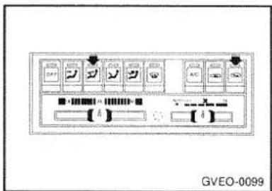
This makes it possible to have cooler air from the dashboard vents and warmer air from the floor outlets at the same time.
To use this feature:
o Select the Bi-level mode door control button.
o Turn off the air conditioner switch.
o Set the air intake control to "FRESH".
For the most comfortable interior setting, move the temperature control lever to the desired position and the blower control lever to the desired position.
VENTILATION

To operate the ventilation system:
o Select the air intake control to "FRESH".
To direct all intake air to the dashboard vents, set the air flow control to "FACE".
For the most comfortable interior setting, move the temperature control lever to the desired position and the blower control lever to the desired position.
DEFROSTING/DEFOGGING

To use the heating/ventilation system to defrost or defog the windshield:
o Push the "DEFROST" mode door control button.
For the most comfortable interior setting, move the temperature control lever to the desired position and the blower control lever to the desired position.
OPERATING TIPS
To keep dust or unpleasant fumes from entering the car through the ventilation system temporarily select the "OFF" mode door control button. Be sure to return the switch to "FRESH" when the irritation has passed to keep fresh air in the vehicle. This will help keep the driver alert and comfortable.
Air for the heating/cooling system is drawn in through the grilles just ahead of the windshield. Care should be taken that these are not blocked by leaves, snow, ice or other obstructions.
NOTE
When driving with "OFF" mode door control button selection, it operates with recirculated inside air and then blower control is stopped and blend door control is stopped.
COOLING CONTROLS

To use the air conditioner to cool interior:
Select one of the mode door control buttons except "OFF" button. If desired, select the "VENT" mode door control button.
o Turn on the air conditioner on-off switch by pushing in on the button.
For normal air conditioner operation, select the "FRESH" air intake control button. For faster cooling, select the "RECIRCULATION" air intake control button.
For the most comfortable interior setting, move the temperature control level to the desired degree and the blower control lever to the desired position.
DEHUMIDIFIED HEATING
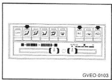
For dehumidified heating
o Select the face mode selection button.
o Turn on the air conditioner switch by pushing in on the button.
0 Select the outside air switching button.
Move the blower switch to the desired speed. For more rapid action, move the blower switch to one of the higher speeds.
o Move the temperature control lever to provide the desired amount of warmth.
Rear air conditioner *

The rear air conditioner operates only when the front air conditioner is in operation. The rear air conditioner switch is at the rear of the centre console.
1- Rear air conditioner switch Slide the rear air conditioner switch to operate the rear air conditioner. There are four fan speeds for control of the amount of airflow.
The rear air conditioner can only be used for cooling. For operations such as defogging, dehumidifying, or air circulation the front air conditioner should be used.
Rear heater *
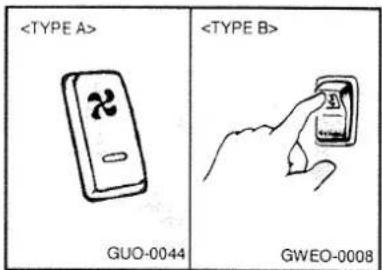
The rear heater can be operated when the ignition switch is at the "ON" position. The indication lamp will illuminate while the rear heater is on.(EU only)
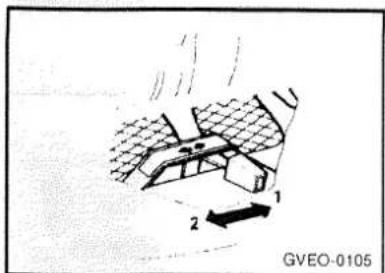
Set the rear heater lever under the rear seat to the "OPEN" position.
1 - SHUT
2 - OPEN
NOTE
When engine coolant temperature is low, output air will be cool.
Set the lever to the "SHUT" position when the rear heater is not in use.
Ventilators
Centre ventilators

Air will flow from the ventilators when the mode selection lever is set to the face position and the fan is switched on.
Adjust the direction of the airflow by moving the louvers.
Side ventilators
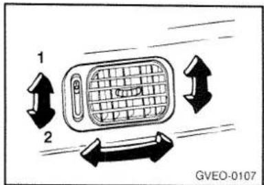
Air will flow from the ventilator when the ventilator lever is in the open position.
1 - Open
2 - Close
The amount of air flow is affected by the wind which will blow into the ventilator while driving.
Adjust the direction of the airflow by moving the louvers.
Roof side ventilators \*

natural_image
Diagram of a car with directional arrows indicating motion, no text or symbols presentAir will flow from the ventilators when the rear air conditioner is switched on.
Adjust the direction of the airflow by moving the louvers.
CASSETTE TAPE PLAYER OPERATION (HMC-600) (If installed)

- POWER ON/OFF, VOLUME CONTROL knob
GVEO-0109
1. POWER ON/OFF, VOLUME CONTROL knob
The radio unit may be operated when the ignition key is in the "ACC" or "ON" position.
Rotate the knob clockwise to switch the radio unit on, and to increase the volume. Turn to the knob counterclockwise to reduce the volume, and to switch the radio unit off.
2. BASS/TREBLE CONTROL
Press to pop the knob out and turn to the left or right for the desired bass tone.
3. BALANCE CONTROL
Press to pop the knob out and turn it clockwise or counterclockwise until sound from the left and right speakers is about equal from your listening position.
4. SEEK OPERATION (Automatic Channel Selection)
When the volume control knob is pressed, the unit will automatically tune to the next higher frequency.
5. TUNE (Manual) SELECTION
When the upper side of the knob is pressed, the frequency will increase in 0.1 MHz steps in FM band, 9 KHz in AM band and vice versa.
With the button held down for 0.5 sec or more, the stop signal (broadcasting radio wave) is ignored, and channel selection continues.
6. PRESET buttons
Six (6) station for AM and FM2 respectively can be preset in the electronic memory circuit on this unit.
HOW TO PRESET STATIONS
Six AM and twelve FM stations may be programmed into the memory of the radio. Then, by simply pressing the band select button and/or one of the six station select buttons, you may recall any of these stations instantly. To program the stations, follow these steps:
o Press band selector to set the band for AM, FM and FM2.
o Select the desired station to be stored by seek, scan or manual tuning.
o Determine the preset station select button you wish to use to access that station.
Press the station select button indicator will show in the display indicating which select button you have depressed. The frequency display will flash after it has been stored into the memory. You should then release the button, and proceed to program the next desired station. A total of 18 stations can be programmed by selecting on AM and two FM stations per button.
When completed, any preset station may be recalled by selecting AM, FM or FM2 band and the appropriate Station button.
7. BAND SELECTOR
Pressing the BAND button changes the AM, FM1 and FM2 bands. The selected is displayed on LCD.
8. TAPE EJECT BUTTON
To eject the tap, press the button.
9. TAPE PROGRAM
When you press the button whose arrow is in the same direction as the tape play arrow in the display the tape will advance at high speed.
When you press the button whose arrow is in the opposite direction to the tape play arrow in the display the tape will rewind at high speed. To stop FF or REW action, press the opposite button. When you press two buttons simultaneously you play the reverse side of the tape and an arrow will appear in the display to show tape direction.
CASSETTE TAPE PLAYER OPERATION (H 810) (If installed)

- POWER ON/OFF, VOLUME CONTROL knob
GVEO-0110
1. POWER ON/OFF, VOLUME CONTROL knob
The radio unit may be operated when the ignition key is in the "ACC" or "ON" position. Rotate the knob clockwise to switch the radio unit on, and to increase the volume. Turn the knob counterclockwise to reduce the volume and to switch the radio unit off.
2. BAL (Balance Control) knob
Pop-up control knob with one push. Turn the control knob clockwise to emphasize right speaker sound. (Left speaker sound will be attenuated)
When the control knob is turned counterclockwise, left speaker sound will be emphasized. (Right speaker sound will be attenuated)
FAD (Fader Control) knob
Further pull-lock position of popped-up knob. Turn the control knob clockwise to emphasize front speaker sound. (Rear speaker sound will be attenuated) When the control knob is turned counterclockwise, rear speaker sound will be emphasized. (Front speaker sound will be attenuated)
3. BASS CONTROL knob
Press to pop the knob out and turn to the left or right for the desired bass tone. TREBLE CONTROL knob
Further pull-lock position of popped-up knob. Turn to the right for the desired treble tone.
4. TUNE (manual) Selection
Press the (+) side or (-) side to increases or decrease the frequency. With the button held down for 0.5 sec. or more, the stop signal (broadcasting radio wave) is ignored and channel selection continues.
5. SEEK Operation (Automatic Channel Selection)
When the (+) side is pressed, the unit will automatically tune to the next higher frequency and when the (-) side is pressed, it will automatically tune the next lower frequency.
6. PRESET STATION SELECT button
Six (6) stations for AM, FM and FM2 respectively can be preset in the electronic memory circuit on this unit.
HOW TO PRESET STATIONS
Six AM and twelve FM stations may be programmed into the memory of the radio. Then, by simply pressing the band select button and/or one of the six station select buttons, you may recall any of these stations instantly. To program the stations, follow these steps:
o Press band selector to set the band for AM, FM and FM2.
o Select the desired station to be stored by seek, scan or manual tuning.
o Determine the preset station select button you wish to use to access that station.
Press the station select button for more than two seconds. A select button indicator will show in the display indicating which select button you have depressed. The frequency display will flash after it has been stored into the memory. You should then release the button, and proceed to program the next desired station. A total of 18 stations can be programmed by selecting one AM and two FM stations per button.
When completed, any preset station may be recalled by selecting AM, FM or FM2 band and the appropriate station button.
7. BAND Selector
Pressing the BAND button change the AM, FM1 and FM2 bands. The mode selected is displayed on LCD.
8. TAPE PROGRAM button
This allows you to play the reverse side of the tape by merely depressing the program button. An arrow will appear in the display to show tape direction.
9. FF/REW/EJECT buttons
When you press the button whose arrow is in the same direction as the tape play arrow in the display the tape will advance at thigh speed. When you press the button whose arrow is in the display the tape will rewind at high speed. To stop FF or REW action, press the opposite button or press the tape program button. But if the tape program button is pressed, it will also reverse the tape play direction. To eject the tape, press the FF and REW buttons simultaneously.
CASSETTE TAPE PLAYER OPERATION (H 820) (If installed)
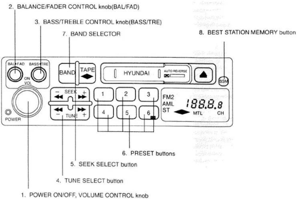
GVEO-0111
1. POWER ON/OFF, VOLUME CONTROL knob
The radio unit may be operated when the ignition key is in the "ACC" or "ON" position. Rotate the knob clockwise to switch the radio unit on, and to increase the volume. Turn the knob counterclockwise to reduce the volume and to switch the radio unit off.
2. BAL (Balance Control) knob
Pop-up control knob with one push. Turn the control knob clockwise to emphasize right speaker sound. (Left speaker sound will be attenuated)
When the control knob is turned counterclockwise, left speaker sound will be emphasized. (Right speaker sound will be attenuated)
FAD (Fader Control) knob
Further pull-lock position of popped-up knob. Turn the control knob clockwise to emphasize front speaker sound.(Rear speaker sound will be attenuated) When the control knob is turned counterclockwise, rear speaker sound will be emphasized. (Front speaker sound will be attenuated)
3. BASS CONTROL knob
Press to pop the knob out and turn to the left or right for the desired bass tone.
TREBLE CONTROL knob
Further pull-lock position of popped-up knob. Turn to the right for the desired treble tone.
4. TUNE (manual) Selection
Press the (+) side or (-) side to increases or decrease the frequency. With the button held down for 0.5 sec. or more, the stop signal (broadcasting radio wave) is ignored and channel selection continues.
5. SEEK Operation (Automatic Channel Selection)
When the (+) side is pressed, the unit will automatically tune to the next higher frequency and when the (-) side is pressed, it will automatically tune the next lower frequency.
6. PRESET STATION SELECT button
Six (6) stations for AM, FM and FM2 respectively can be preset in the electronic memory circuit on this unit.
HOW TO PRESET STATIONS
Six AM and twelve FM stations may be programmed into the memory of the radio. Then, by simply pressing the band select button and/or one of the six station select buttons, you may recall any of these stations instantly. To program the stations, follow these steps:
o Press band selector to set the band for AM, FM and FM2.
o Select the desired station to be stored by seek, scan or manual tuning.
o Determine the preset station select button you wish to use to access that station.
Press the station select button for more than two seconds. A select button indicator will show in the display indicating which select button you have depressed. The frequency display will flash after it has been stored into the memory. You should then release the button, and proceed to program the next desired station. A total of 18 stations can be programmed by selecting one AM and two FM stations per button.
When completed, any preset station may be recalled by selecting AM, FM or FM2 band and the appropriate station button.
7. BAND Selector
Pressing the BAND button change the AM, FM1 and FM2 bands. The mode selected is displayed on LCD.
8. BEST STATION MEMORY button (BSM)
When the BSM button is pressed for two seconds or longer, the preceding memory is all cleared, and six channels with the highest field intensity are selected and kept in memory of the preset key in the sequence of frequencies.
CASSETTE TAPE PLAYER OPERATION (H 820) (If installed)

- FF/REW button
GVEO-0111
1. FF/REW button
0 The FF (fast forward tape winding) starts when the (+) side pressed during the PLAY or REW.
0 The play starts when the (+) side is pressed again during the FF.
o The REW (rewinding) starts when the (-) side is pressed during the PLAY or FF.
o The play starts when the (-) side is pressed again during the REW.
2. AUTO MUSIC SELECT button
Press the button to find the starting point of each song in prerecorded music tape. The quiet space between songs (must have at least a 4 sec. gap) can be accepted by the AUTO MUSIC SELECT button.
o Pressing the (+) side will play the beginning of the next music segment.
o Pressing the (-) side will start replay at the beginning of the music just listened to.
3. TAPE PROGRAM button
This allows you to play the reverse side of the tape by merely depressing the program button.
An arrow will appear in the display to show tape direction.
4. EJECT button
When the EJECT button is pressed with the cassette loaded, the cassette is ejected.
When the EJECT button is pressed during the FF/REW, the cassette is ejected.
5. DOLBY SELECT button
If you get background noise during PLAY, your can reduce this considerably by merely pressing DOLBY SELECT button. If you want to release, press the button again.
STEREO RADIO OPERATION (H 850) (If installed)

1. POWER ON-OFF, VOLUME CONTROL knob
The radio unit may be operated when the ignition key is in the "ACC" or "ON" position. Press the button to switch the power on. The VFD (Vacuum Florescent Display) shows the radio frequency in the radio mode, or the tape direction indicator in the tape mode. To switch the power off, press the button again.
VOLUME CONTROL
Rotate the knob clockwise to increase the volume and turn the knob counterclockwise to reduce the volume. The VFD shows the change the volume.
2. AUDIO MODE Knob
Each press the [A.MODE] button changes the display as follows;

1) Adjusting Bass
Press the [A. MODE] button one time and the display shows;
To increase bass, press the Δ button, while to decrease bass, press the button.

2) Adjusting Treble
Press the [A. MODE] button twice and the display shows ;

Press the Δ button increase the treble, while the button decreases the treble.
3) Adjusting Balance
Press the [A. MODE] button three times and the display shows ;

Press the Δ button shift the balance to the right speakers, while the button shifts it to the left speakers.
4) Adjusting the Fader
Balancing the volume between the front and rear speakers.
Press the [A.MODE] button four times and the display shows;
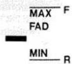
Press the Δ button transfers the sound to the front speaker, while the button transfers it to the rear speakers.
3. TUNE (manual) Selection
Press the (+) side or (-) side to increases or decrease the frequency. With the button held down for 0.5 sec. or more, the stop signal (broadcasting radio wave) is ignored and channel selection continues.
4. SEEK Operation (Automatic Channel Selection)
When the (+) side is pressed, the unit will automatically tune to the next higher frequency and when the (-) side is pressed, it will automatically tune the next lower frequency.
- PRESET STATION SELECT button Six (6) stations for AM, FM and FM2 respectively can be preset in the electronic memory circuit on this unit.
HOW TO PRESET STATIONS
Six AM and twelve FM stations may be programmed into the memory of the radio. Then, by simply pressing the band select button and/or one of the six station select buttons, you may recall any of these stations instantly. To program the stations, follow these steps:
o Press band selector to set the band for AM, FM and FM2.
o Select the desired station to be stored by seek, scan or manual tuning.
Determine the preset station select button you wish to use to access that station.
o Press the station select button for more than two seconds. A select button indicator will show in the display indicating which select button you have depressed. The frequency display will flash after it has been stored into the memory. You should then release the button, and proceed to program the next desired station. A total of 18 stations can be programmed by selecting one AM and two FM stations per button.
When completed, any preset station may be recalled by selecting AM, FM or FM2 band and the appropriate station button.
6. BAND Selector
Pressing the BAND button change the AM, FM1 and FM2 bands. The mode selected is displayed on the LCD.
7. BEST STATION MEMORY button (BSM)
When the BSM button is pressed for two seconds or longer, the preceding memory is all cleared, and six channels with the highest field intensity are selected and stored in memory. The stations selected are stored in the sequence of the preset key.
CASSETTE TAPE PLAYER OPERATION (H 850) (If installed)

GVEO-0209
1. FF/REW button
The FF (last forward tape winding) starts when the (+) side is pressed during the PLAY or REW modes.
o Tape play starts when the (+) side is pressed again during the FF.
The REW (rewinding) starts when the (-) side is pressed during the PLAY or FF modes.
o The play starts when the (-) side is pressed again during the REW.
2. AUTO MUSIC SELECT button
Press the button to find the starting point of each song in prerecorded music tape. The quiet space between songs (must have at least a 4 sec. gap) can be accepted by the AUTO MUSIC SELECT button.
o Pressing the (+) side will play the beginning of the next music segment.
o Pressing the (-) side will start replay at the beginning of the music just listened to.
3. TAPE PROGRAM button
This allows you to play the reverse side of the tape by merely depressing the program button.
An arrow will appear in the display to show tape direction.
4. EJECT button
When the EJECT button is pressed with the cassette loaded, the cassette is ejected.
When the EJECT button is pressed during the FF/REW mode, the cassette is ejected.
5. DOLBY SELECT button
If you get background noise during PLAY, your can reduce this considerably by merely pressing DOLBY SELECT button.
If you want to release, press the button again.
COMPACT DISC PLAYER OPERATION (H 850) (If installed)
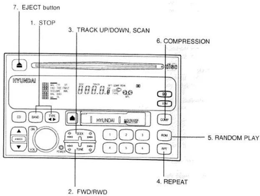
GVED-0209
1. STOP
o Insert the CD to start CD playback, during the radio operation or cassette tape playing.
o Press the TM or TAPE buttons to stop CD playback and to change the source to Radio or Cassette Tape.
2. FWD/RWD
While the disc is playing, if you hold down the (+) side continuously, the track number is increased and vice versa.
3. TRACK UP/DOWN, SCAN
The desired track on the disc currently being played can be selected using the track number.
o Pressing the (+) side once increases the track number by one and pressing the (-) side decreases it.
SCAN
o Press the (+) or (-) side for more than two seconds to playback the first 5 seconds of each track.
0 Scan play will be repeated until you release SCAN operation.
To release SCAN operation, press the SEEK button again.
4. REPEAT
To repeat the music you are listening to, press the RPT button and to cancel music repeat, press again.
If you do not release RPT operation after all the tracks are played back, the unit will play back again from the first track.
5. RANDOM PLAY
0 A disc will be played back in a random sequence.
o Press the RANDOM button to play back in a random sequence while the disc is playing.
After all the tracks are played back, the unit will play back again in random sequence. The same track will not be played back twice in one cycle of the disc.
6. Compression
Press the COMPRESSION button to activate the Compression function.
Press the COMPRESSION button again to deactivate.
This feature allows the unit to narrow the dynamic range (difference between high and law volume) to decrease the rapid change in sound difference when you change from tape/radio mode to disc mode.
Care of DISC
Proper Handing

natural_image
Illustration of two hands holding a CD or DVD disc with a small object inserted, labeled MVEO-0001 (no text or symbols on the diagram itself)Handle your disc as shown. Do not drop the disc. Hold the disc so you will not leave fingerprints on the surface. If the surface is scratched, it may cause the pickup to skip signal tracks. Do not affix tape, paper, or gummed labels on the disc. Do not write on the disc.
Damage Disc
Do not attempt to play damaged, warped or cracked discs. It could severely damaged the playback mechanism.
Storage
When not in use, place your disc in their individual case and store them in a cool place away from the sun, heat, and dust.
Do not grip or pull out the disc with your hand while the disc is being pulled into the unit by Self Loading mechanism.
Do not pull the unit from the dash immediately after a disc is inserted or the Eject Switch has been pressed. If the unit is pulled out before an operation is completed, the disc will be unstable in the unit and may be damaged.
Do not attempted to insert a disc into the unit when the unit is out of the dash or the power is off.

natural_image
Line drawing of a hand holding a circular object with an arrow indicating motion (no text or symbols)Keep Your Discs clean
Fingerprints, dust or soil on the surface could cause the pickup to skip signal tracks. Wipe the surface clean with a clean soft cloth. If the surface is heavily soiled, dampen a clean soft cloth in a solution of mild neutral detergent to wipe it clean. See drawing.
HEAD CLEANING

The playback head performs an important role in the reproduction of recordings. If the head should become dirty, tone quality suffers and skipping will occur, so the head should be cleaned periodically every one or two months.
If a cotton swab is used, dip the swab into absolute alcohol or head cleaning fluid and use it to scrub the slit in the tape head.
NOTE
0 Don't use metal or magnet on the head.
Never use tweezers or pliers wrapped with cotton or gauze because you will scratch the head.
When using a cleaning tape, play it once on one side for normal cleaning, too much use of the cleaning tape will increase head wear. Be sure to read the cleaning tape instructions before use.
CAUTION
o Use ungrounded speakers only.
o Do not ground any of the speaker terminals.
Be sure to insulate exposed wiring so as to protect it from short circuit if touched with some metal items.
CASSETTE CARE

natural_image
Cartoon illustration of a character labeled C-120 interacting with a large block, no text or symbols present- When the unit is not in operation, remove the cassette from the player and keep it in its plastic case.
- Keep the tape away from direct sunlight, dirt or dust, do not touch the tape surface with your fingers to avoid oil accumulating on the tape.
- Do not use cassette tape lasting more than C-90 (90 MIN.) C-120 or C-180 tape is extremely thin and sometimes tangles in the drive mechanism. It's use should be avoided if at all possible.
-
Always be sure that the tape is tightly wound on its reel before inserting in the player. Rotate a pencil in the drive sprockets to wind up any slack.
-
If the tape has been unevenly wound, the force required for tape transport is too high which will cause play to switch automatically to the other side (The unit senses that the tape has reached the end). When this happens, use fast forward to rewind the tape uniformly before attempting playback.
- Before inserting the tape, make sure that the label is adhering flatly to the cassette.
- Keep the cassette away from magnetized objects (motor, speaker, transformer, ETC.). This is to avoid unwanted noise and loss of the tone quality of the tape.
- Keep the cassette in a cool, dry place.
POWER ANTENNA (If installed)
The antenna will automatically be extended when the radio power switch is turned "ON". The antenna will automatically be retracted and stored when either the radio power switch is turned "OFF" or the ignition key is set to the "LOCK" position.
NOTE
Before turning on the radio, make sure that no one is near the antenna.
Before entering an automatic car wash or a place with a low height clearance, be sure that the antenna is retracted and stored.
o If the antenna is dirty, be sure to clean it in order to avoid an operation malfunction.
Starting and driving
Ignition switch
Starting the engine
Engine rpm adjustment knob *
Manual transmission
Transfer shift lever
Automatic transmission*
Free wheeling hubs
Correct four wheel drive operation
Parking brake
Inside rear-view mirror
Outside rear-view mirrors
Outside rear-view mirrors heater*
Ignition switch

1 - The engine stops and the steering wheel is locked. The key can be inserted and removed only at this position.
2 - The engine stops, but the radio, cigarette lighter, etc., can be operated.
3 - The engine is running and all electrical systems can be operated.
For diesel powered vehicles, the glow plug is to be preheated at this position before starting the engine.
4 - The starter motor operates. After the engine has started, release the key and it will automatically return to the "ON" position.
CAUTION
If the key is accidentally removed, the steering wheel will lock, making it impossible to control the vehicle.
(1) If the engine is stopped while driving, the brake servomechanism will cease to function and braking efficiency will deteriorate.
(2) Do not leave the key at the "ON" position for a long time when the engine is not running; doing so will cause the battery to be discharged.
(3) Do not turn the key to the "START" position when the engine is running; doing so could damage the starter motor.
(4) Remove the key when leaving the vehicle.
How to lock and unlock the steering wheel
TO LOCK
Turn the key to the "LOCK" position. Slightly turn the steering wheel until it is locked.
TO UNLOCK

natural_image
Illustration of hands holding a ring device with a camera (no text or symbols)Turn the key to the "ACC" position while moving the steering wheel slightly.
CAUTION
If the key is accidentally removed, the steering wheel will lock, making it impossible to control the vehicle.
Starting the engine Tips for starting
(1) Do not operate the starter motor continuously for longer than ten seconds; doing so could run down the battery. If the engine does not start, turn the ignition switch back to "LOCK", wait a few minutes, and then try again.
(2) If the engine cannot be started because the battery is weak or dead, refer to the emergency starting section for instructions on starting the engine.
(3) After starting the engine, do not keep the engine idling without driving. Only when the atmospheric temperature is very low, warm up the engine at a high idling speed to ensure proper circulation of the oil.
CAUTION
(1) For petrol powered vehicles, do not keep the engine running for a long time in a closed or poorly ventilated place. Carbon Monoxide gas is odorless and extremely poisonous.
(2) Do not run the engine at high rpm or drive the vehicle at high speed until the engine has had a chance to warm up.
(3) Release the ignition key as soon as the engine starts to avoid damaging the starter motor.
(4) For diesel powered vehicles do not stop the engine immediately after operating the vehicle at high speeds. Allow the engine to idle for approximately 60 seconds or more to give the turbocharger a chance to cool down.
Starting the engine (diesel-powered vehicles)

VEHICLES EQUIPPED WITH DIESEL PREHEAT INDICATION LAMP
- Apply the parking brake.
- On vehicles with a manual transmission, move the gearshift lever to neutral and depress the clutch pedal all the way. On vehicles with an automatic transmission, move the selector lever to the "P" position.
- Turn the ignition key to the "ON" position. The diesel preheat indication lamp will first illuminate in amber, and then after a short time the lamp turn off, indicating that preheating is completed.
- Operate the accelerator pedal as described below in accordance with the atmospheric temperature and/or engine condition and then start the engine.
(1) When the atmospheric temperature is moderate or the engine is warm, start the engine without depressing the accelerator pedal.
(2) When the atmospheric temperature is low and the engine is cold, start the engine while depressing the accelerator pedal. If the atmospheric temperature is very low, setting the ignition switch to ON for one or two seconds before attempting to start the engine will make it easier to start.
Engine rpm adjustment knob \*
When the outside air temperature is very low, or when it is necessary to warm up the engine, rotate the control knob to that point at which the engine runs smoothly, and then, once the warming up is complete, rotate the knob back in.
CAUTION
Never attempt to adjust the vehicle during driving by using the control knob.
Starting the engine (gasoline-powered vehicles) FUEL INJECTION TYPE
This vehicle is equipped with an electronically controlled injection device and fuel injection amount is automatically controlled. When starting the engine, do not depress the accelerator pedal.
- Apply the parking brake.
- On vehicles with a manual transmission, move the gearshift lever to neutral and depress the clutch pedal all the way. On vehicles with an automatic transmission, move the selector lever to the "P" position.
- Start the engine without depressing the accelerator pedal.
NOTE
If the engine has become flooded during starting, first operate the starter 5 or 6 seconds while depressing the accelerator pedal fully, and then start the engine without depressing the accelerator pedal.
At extreme cold ambient temperature
If the engine won't start, depress the accelerator pedal about halfway during cranking the engine. Once the engine starts, release the accelerator pedal.
Manual transmission
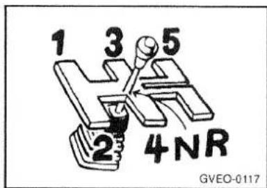
The shift pattern is shown on the gearshift lever knob. Be sure to always fully depress the clutch pedal before attempting to shift the lever.
To shift into reverse from 5th gear, move the gearshift lever to neutral, and then shift it into reverse.
CAUTION
Do not move the gearshift lever into reverse while the vehicle is moving forward; doing so will damage the transmission.
Transfer shift lever

This lever is used to select between rear-wheel drive and four-wheel drive, and low-speed, high-speed, and neutral.
If the transfer shift lever is set to either the "4H" or the "4L" position while the ignition key is at the "ON" position, the 4WD indication lamp will illuminate.
Lever position
2H- High-speed two-wheel drive
The two rear wheels will be driven; this position should be used for high-speed driving or for driving on normal roads.
4H- High-speed four-wheel drive
All four wheels will be driven; this position should be used for driving in snow, sand, on rough roads, or at other times when increased drive power is needed.
and when driving is done at normal speed.
N- Neutral
This position should be used when the mechanical winch is to be operated (if installed); the vehicle cannot be driven with the lever in this position.
NOTE
The "N" position is only on models with a manual transmission.
4L- Low-speed four-wheel drive
All four wheels will be driven; this position should be used for ascending or descending steep grades, driving in mud, or at other times when increased drive power is needed. The drive power is the greatest when the lever is at this position.
CAUTION
(1) Four wheel drive should never be used on paved road surfaces. Don't drive your vehicle in the "4L" position on the public road; this would result in early wear of the tyres, clutch and other parts, increased fuel consumption and possible noise generation.
(2) Use 1st gear in the "4L" position for very low speed off road driving.
Lever operation (vehicles equipped with manual free wheeling hubs)
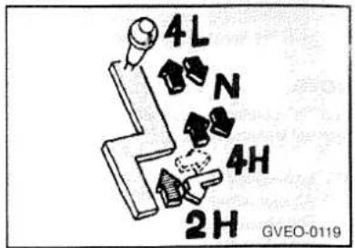
“2H” → “4H”
The vehicle must be temporarily stopped and both the left and right free wheeling hubs must be set to the "LOCK" position. The lever can then be operated in this way while the vehicle is either stopped or moving, with or without depressing the clutch pedal.
At the position, the lever will move automatically without pressing it, by spring action.
NOTE
If lever operation is stiff, depress the accelerator pedal lightly while operating the lever.
←“4H”→“N”→“4L”
The lever can be operated between these positions while the vehicle is stopped and the clutch pedal is depressed.
“4H”→“2H”
The lever can be operated in this way while the vehicle is either stopped or moving, with or without depressing the clutch pedal.
CAUTION
- If four wheel drive is to be used, be sure to set both the left and the right manual free wheeling hubs to the "LOCK" position.
- When the transfer shift lever is to be shifted from 2H or 4H to 4L, and vice versa, keep the vehicle completely stopped and automatic transmission selector lever at the "P" or "N" position beforehand.
- If shifting is difficult, set the automatic transmission selector lever to the "R" position for a moment and then to the "P" or "N" position. Try to shift the transfer shift lever to 2H, 4H or 4L again still keeping the vehicle completely stopped.
4 When switching from 4H to 4L or from 4L to 4H with the automatic transmission selector lever in neutral, perform the switchover quickly. If it is done too slowly, the transmission gears may grind.
Lever operation (vehicles equipped with automatic free wheeling hubs)

“2H” → “4H”
The lever can be operated in this way while the vehicle is stopped, with or without depressing the clutch pedal.
At the position, the lever will move automatically, without pressing it, by spring action.
NOTE
After the lever has been set to the "4H" position and the vehicle is driven a short distance, the free wheeling hubs will automatically lock and the vehicle will change to four wheel drive.
← "4H" → "N" → "4L"
The lever can be operated between these positions while the vehicle is stopped the clutch lever is depressed.
"4H"→"2H"
The lever can be operated in this way while the vehicle is either stopped or moving, with or without depressing the clutch pedal.
NOTE
After the lever has been set to the "2H" position and slowly reverse the vehicle in a straight direction for 1 to 2m (3.3 to 6.6ft.), the free wheeling hubs will automatically unlock.
CAUTION
- When the transfer shift lever is to be shifted from 2H or 4H to 4L, and vice versa, keep the vehicle completely stopped and the automatic transmission selector lever at the "P" or "N" position beforehand.
- If shifting is difficult, set the automatic transmission selector lever to the "R" position for a moment and then to the "P" or "N" position. Try to shift the transfer shift lever to 2H, 4H or 4L again still keeping the vehicle completely stopped.
- When switching from 4H to 4L or from 4L to 4H with the automatic transmission selector lever in neutral, perform the switchover quickly. If it is done too slowly, the transmission gear may grind.
Changing gears
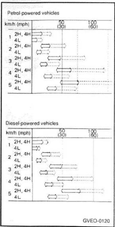
line
Petrol-powered vehicles | Vehicle Type | Speed Range (mph) | Speed (mph) | | :--- | :--- | :--- | | 1 | 2H, 4H | 4L | | 1 | 2H, 4H | 4L | | 1 | 2H, 4H | 4L | | 2 | 2H, 4H | 4L | | 2 | 2H, 4H | 4L | | 2 | 2H, 4H | 4L | | 3 | 2H, 4H | 4L | | 3 | 2H, 4H | 4L | | 3 | 2H, 4H | 4L | | 4 | 2H, 4H | 4L | | 4 | 2H, 4H | 4L | | 5 | 2H, 4H | 4L | | Diesel-powered vehicles | Speed Range (mph) | Speed (mph) | | 1 | 2H, 4H | 4L | | 1 | 2H, 4H | 4L | | 2 | 2H, 4H | 4L | | 2 | 2H, 4H | 4L | | 3 | 2H, 4H | 4L | | 3 | 2H, 4H | 4L | | 4 | 2H, 4H | 4L | | 4 | 2H, 4H | 4L | | 5 | 2H, 4H | 4L | GVEO-0120Always use care to change the gear with the vehicle speed matched to the engine speed. Proper shifting will improve fuel economy and prolong engine life.
Avoid shifting down at excessively high speed; doing so could damage the engine.
Economical driving range ⇌ Possible driving range
Automatic transmission\*

The transmission has four forward speeds and one reverse speed.
The individual gears are selected automatically, depending on the position of the gear selector lever, the speed of the vehicle and the position of the accelerator pedal.
The selector lever has six positions, and is equipped with a lock button to avoid inadvertent selection of the wrong gear.
Button must be pressed to move the selector lever.
Button need not be pressed to move the selector lever.
Selector positions
P-PARK
This position locks the transmission to prevent the vehicle from moving. The engine can be started in this position.
Never move the lever to the "P" position while the vehicle is moving.
R-REVERSE
Move the lever to this position only after the vehicle has come to a complete stop.
N-NEUTRAL
At this position the transmission is disengaged. It is the same as the neutral position on a manual transmission, and should be used when the vehicle is stationary for an extended length of time during driving, such as in a traffic jam.
CAUTION
Do not shift to the "N" position while traveling as the engine brake will be made inoperative.
D-DRIVE
This position is used for most city and highway driving, for movement from a full stop to maximum speed.
To protect the automatic transmission, a speed of 150 km/h (93 mph) should not be exceed while the overdrive control switch is pressed.
2-SECOND
This position is for extra power when driving up moderately steep hills, and for engine braking when descending moderately steep grades.
To prevent engine damage, always select the appropriate gear. A speed of 90 km/h (55 mph) should not be exceeded in "2" gear.
A change from "D" to "2" should not be made if the driving speed exceeds 90 km/h (55 mph).
L-LOW
This position is for driving up very steep hills and for engine braking at low speed when descending steep grades.
To prevent engine damage, always select the appropriate gear. A speed of 50 km/h (30 mph) should not be exceeded in "L" gear.
A change from "2" to "L" should not be made if the driving speed exceed 50 km/h (30 mph).
OVERDRIVE CONTROL
SWITCH
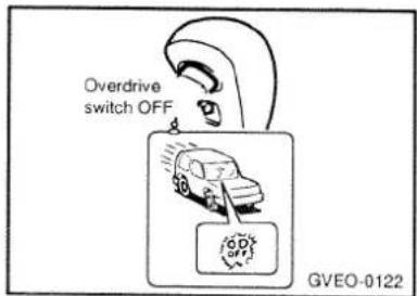
Automatic shifting will be done from 1st gear through 4th gear if the selector lever is set to "D" while the overdrive control switch is not pressed. If the switch is pressed, automatic shifting will be from 1st gear through 3rd gear. Depressing the overdrive control switch during high-speed driving will allow effective use of 4th gear and result in more economical driving. However, because automatic shifting to 4th gear during a long uphill; or downhill grade would decrease the climbing ability or engine braking effectiveness, press the overdrive control switch at these times.
Operation
Before selecting a gear with the engine running and the vehicle stationary, either engage the parking brake or depress the service brake.
Because the vehicle will begin to move as soon as the gear is engaged, especially when the engine rpm is high, the brakes should only be released when you are ready to drive away.
CAUTION
To prevent sudden acceleration never race the engine when shifting from the "P" or "N".
Passing acceleration
For quick acceleration when passing, depressing the accelerator pedal all the way to the floor will cause the transmission to automatically shift from 4th gear to 3rd gear, from 3rd gear to 2nd gear or from 2nd gear to 1st gear, in accordance with the driving speed at the time, without having to move the selector lever from "D" or "2".
Waiting
For short waiting periods such as at traffic lights, the vehicle can be left in gear and held stationary with the service brake.
For longer waiting periods with the engine running, the selector lever should be set the "N" position.
CAUTION
Never hold the vehicle stationary while in gear on a hill with the accelerator; always apply the parking brake and/or service brake.
Parking
To park the vehicle, first bring it to a complete stop, fully engage the parking brake, and then set the selector lever to "P".
If you are going to leave the vehicle unattended, be sure to always turn off the engine and remove the ignition key.
Free wheeling hubs
If the vehicle is equipped with free wheeling hubs, they are located on the front wheels. By setting the free wheeling hubs to the "FREE" position when the shift lever is in the "2H" position, the drive power of the front drive line for the front wheels can be discontinued, thus resulting in more economical operation in addition to reduced noise.
By setting the free wheeling hubs to the "LOCK" position when the shift lever is in either the "4H" position or the "4L" position, the drive power of the front drive line can be transmitted to the front wheels.
Manual free wheeling hubs
The hubs are set to either the "FREE" position or the "LOCK" position by turning the handle.
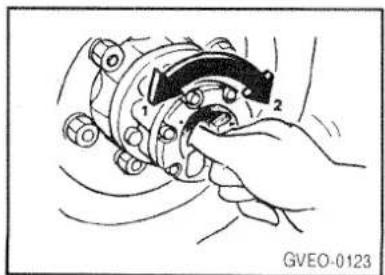
natural_image
Hand operating a mechanical component with labeled parts (1 and 2), no visible text or symbols beyond labels1 - FREE
This position is for rear wheel drive.
2 - LOCK
This position is for four wheel drive.
CAUTION
If four wheel drive is to be used, both the left and right free wheeling hubs must be set to the "LOCK" position. Do not attempt to drive the vehicle with the transfer shift lever in either the "4H" or "4L" position if the free wheeling hubs are in the "FREE" position.
If the setting of the free wheeling hubs is to be changed after extended use of the brakes (such as for descending a long slope), allow them to cool first. The free wheeling hubs can become extremely hot and could cause severe burns.
Automatic free wheeling hubs

The hubs are automatically locked or unlocked according to the position of the transfer shift lever during driving.
TO LOCK THE HUBS:
Bring the vehicle to a complete stop, move the transfer shift lever from "2H" to "4H" and then resume driving; the hubs will lock automatically, and four-wheel drive will begin.
TO UNLOCK THE HUBS:
Move the transfer shift lever from "4H" to "2H" and slowly reverse the vehicle straight back for 1 to 2 m (3.3 to 6.6 ft.); the hubs will automatically unlock, and rear-wheel drive will be resumed.
The automatic free-wheeling hubs may make a noise when locking or unlocking, however, this does not indicate any malfunction.
For rear-wheel drive on roads in good condition, the automatic free-wheeling hubs should be unlocked.
If changing from four-wheel drive to rear-wheel drive is to be done intermittently, it is possible to leave the automatic free-wheeling hubs locked. If this is done, the change to four-wheel drive can be made while driving, without stopping the vehicle. The automatic free-wheeling hubs will remain locked during rear-wheel drive if the transfer shift lever is moved to "2H" during driving.
CAUTION
(1) Even if automatic free-wheeling hubs are left locked during rear-wheel drive, they will be unlocked if the vehicle is reversed during starting on an uphill grade, a U-turn, etc. If this happens, the transfer shift lever cannot be moved to the "4H" position during driving; the vehicle must first be completely stopped.
(2) If, during four-wheel drive operation, the vehicle becomes stuck and a back-and-forth rocking motion is used to free it, the automatic freewheeling hubs may become unlocked because of the backward movement. If the engine is subsequently revved up and the clutch let out suddenly, the automatic freewheeling hubs may not lock, and a
noise of grinding gears will be heard, however, this is not a malfunction. In addition, if in this condition the accelerator pedal is released slightly and then depressed again, the automatic free-wheeling hubs will lock, but when they do, the vehicle may jerk forward suddenly. Depress the accelerator pedal gradually, and let the clutch out slowly and smoothly.
(3) The automatic free-wheeling hubs may emit unusual noises when driving at "2H" in cold weather; if this happens, drive for a while in four-wheel drive to warm up the transfer and then shift to "2H".
(4) When used while turning, it may not come free in some cases. If this happens, drive straight ahead and try again.
(5) It may not come free in some cases when temperatures are low; therefore, in cold weather, free immediately after driving in 4-wheel drive. If this does not work, try again using one of the following methods.
o Drive for a while (approx. 10 minutes) in 4-wheel drive and try again.
Drive straight forward slowly for 1 to 2 meters (3.3 to 6.6 ft.) and then back up, repeating this procedure several times.
(6) It is very important that any repairs of the automatic freewheeling hubs be done correctly. Have any such repairs done only at a GALLOPER dealer.
Correct four wheel drive operation
By shifting to four-wheel drive, the both axles of the vehicle are rigidly connected with each other. This improves the traction characteristics. When turning sharp corners or moving forward and backward repeatedly, however, the drive line is stressed, which is felt as a braking effect. A four-wheel drive vehicle can accelerate more quickly and smoothly.
However, note that the braking distance is not shorter than that of a two wheel drive vehicle. When using four wheel drive on rough roads(snow, mud, sand, etc.), it is important to operate the vehicle correctly.
NOTE
After driving on rough roads, check each part of the vehicle and wash it thoroughly with water. Refer to the "Vehicle care" section.
Driving on snowy or icy roads
Set the transfer shift lever to "4H" or "4L" in accordance with the road conditions, and then gradually depress the accelerator pedal for a smooth start.
NOTE
(1) The use of snow tyres and/or tyre chains is recommended.
(2) Maintain a safe distance between vehicles, avoid sudden braking, and use engine braking (downshifting).
(3) Avoid sudden braking, sudden acceleration and sharp turning; such operations could cause skidding and spinouts.
Driving on sandy or muddy roads
Set the transfer shift lever to "4L", and then gradually depress the accelerator pedal for a smooth start. Keep the pressure on the accelerator pedal as constant: as possible, and drive at low speed.
NOTE
(1) Avoid sudden braking, acceleration and turning; such operations could result in the vehicle becoming stuck.
(2) If it is necessary to drive in extremely muddy conditions, the use of tyre chains is recommended.
(3) If the vehicle becomes stuck, place stones, tree branches, etc. under the tyres to provide traction, or rock the vehicle back and forth to get it loose.
(4) Because the extent of muddy conditions is difficult to judge and the vehicle could become bogged down very deeply, operation should be at a low speed. If possible, get out of the vehicle and check the conditions ahead before proceeding.
CAUTION
Driving over roads in coastal areas or roads on which anti-skid preparations have been spread can cause rust on the vehicle; wash the vehicle thoroughly as soon as possible after such use.
Climbing sharp grades
Set the transfer shift lever to "4L" to maximize use of the engine torque.
(1) Choose as smooth a slope as possible.
(2) The climbing ability is a 35° grade on dry pavement.
(3) Before attempting to drive up the slope, walk up it to confirm that the vehicle can handle the grade.
Descending sharp grades
Set the transfer shift lever to "4L", use the engine brake (downshifting) and descend slowly.
(1) When descending a sharp grade, if the brakes are applied suddenly because of an obstacle encountered, control of the vehicle could be lost. Before descending the slope, walk down it and confirm the path.
(2) Before descending a grade, it is necessary to choose the appropriate gear. Avoid changing gears or depressing the clutch while descending the grade.
Turning sharp corners
When turning a sharp corner in four-wheel drive, the same thing that happens when doing so with the brake applied may occur. This is called tight corner braking, and results from each of the four tyres being at a different distance from the corner. The phenomenon is peculiar to four-wheel drive vehicles. If this occurs, either straighten out the steering wheel, or change to two-wheel drive.
Crossing a stream
Four wheel drive vehicles are not necessarily waterproof. If the electrical circuits become wet, further operation of the vehicle will be impossible; therefore, avoid crossing streams unless absolutely necessary. If crossing a stream is unavoidable, use the following procedure:
(1) Cross at a place where the water is less than 50 cm(1.6ft.) deep.
(2) Set the transfer shift lever to "4L".
(3) Drive slowly at a speed of approximately 5 Km/h (3 mph) to avoid splashing too much water.
CAUTION
Do not attempt to cross a stream at a place where the water is more than 50 cm(1.6ft.) deep.
Do not change gears while crossing the stream.
Frequent crossing of streams can adversely affect the life span of the vehicle; consult a GALLOPER dealer and take the necessary measures to prepare, inspect, and repair the vehicle.
After crossing a stream:
Inspect the brakes to be sure they are functioning properly. If the brakes are wet and not functioning properly, dry them out by driving slowly while lightly depressing the brake pedal.
o Inspect each part of the vehicle carefully. Refer to the "Inspection and maintenance following rough road operation" section.
Inspection and maintenance following rough road operation
After operation the vehicle in rough road conditions, be sure to perform the following inspection and maintenance procedures:
(1) Check that the vehicle has not been damaged by rocks, gravel, etc.
(2) Carefully wash the vehicle with water. Drive the vehicle slowly while lightly depressing the brake pedal in order to dry out the brakes. If the brakes still do not function properly, contact a GALLOPER dealer as soon as possible to have the brakes checked.
(3) If a stream has been crossed, check the engine, transmission, and differential oil. If the oil is milky or cloudy, water has become mixed in with it and it must be replaced with new oil.
Parking brake

natural_image
Illustration of a hand holding a tool with a pointed tip and arrow, no text or symbols presentTo park the vehicle, first bring it to a complete stop, fully engage the parking brake, and then set the gearshift lever 1st or reverse for vehicles with manual transmission. Move the transfer shift lever to any position except "N".
1 - To apply, pull the lever up without pushing the button at the end of hand grip.

2 - To release, pull the lever up slightly, push the button, and then push it downward.
CAUTION
Before driving, be sure that the parking brake is fully released and brake warning lamp is off.
Inside rear-view mirror

The lever at the bottom of the mirror can be used to adjust the mirror to reduce the glare from the headlights of vehicles behind you during night driving.
1 - Normal
2 - Anti-glare
Outside rear-view mirrors

Place the select switch to the same side as the mirror whose adjustment is desired:
L - Left outside mirror adjustment
R - Right outside mirror adjustment
Press the mirror switch to adjust the mirrors.
Outside rear-view mirrors heater \* (if installed)
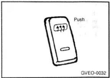
The outside rearview mirror heater is actuated in connection with rear window defroster. So, to heat the outside rearview mirror glass, push in the switch for rear window defroster. The rearview mirror glass will be heated for defrosting or defogging and will give you improved rear vision in all weather conditions. Push the switch again to turn the heater off. The outside rearview mirror heater automatically turns itself off after 10 seconds.
Vehicle care
Washing
Waxing
Polishing
Wheels
Chrome parts
Plastic and rubber part
Damaged paint
Tar
Window glass
Wiper blades
Engine compartment
Upholstery and interior
Tyre care
In order to maintain the value of your vehicle, it is necessary to perform regular maintenance using the proper procedures. Be sure to maintain your vehicle in compliance with any pertinent environmental pollution control regulations.
Carefully select the materials to be used for washing, etc., to be sure that they do not contain corrosive; if in doubt, contact a GAL-LOPER dealer for assistance in the selection of these materials.
Washing
Chemicals contained in the dirt and dust picked up from the road surface can damage the paint coat and body of your vehicle if left in prolonged contact.
Frequent washing and waxing is the best way to protect your vehicle from this damage. This will also be effective in protecting it from environmental elements such as rain, snow, salt air, etc.
Do not wash the vehicle in direct sunlight. Park the vehicle in the shade and spray it water to remove dust. Next, using an ample amount of clean water and a vehicle washing brush or sponge, wash the vehicle from top to bottom.
Use a mild vehicle washing soap if necessary. Rinse thoroughly and wipe dry with a soft cloth. After washing the vehicle, carefully clean the joints and flanges of the doors, hood, etc., where dirt is likely to remain.
NOTE
(1) Try to refrain from using a car wash as its brushes may scratch the paint surface, causing it to lose its gloss. Scratches will be especially visible on darker colored vehicles.
(2) Do not spray or splash water onto the electrical components in the engine compartment, because to do so may adversely affect starting.
Waxing
Waxing the vehicle will help prevent the adherence of dust and road chemicals to the paintwork. Apply a wax solution after washing the vehicle, and apply wax at least once every three months.
Do not wax your vehicle in direct sunlight. You should wax after the surfaces have cooled.
Waxes containing high abrasive compounds should not be used.
Such waxes remove rust and stain effectively from the paintwork but they are harmful to the luster of the painted surface, since they also scrape off the coating.
Further, they are detrimental to glossy surfaces such as grille, garnish, molding, etc.
Do not use petrol or paint thinners to remove road tar or other contamination to the painted surface.
Polishing
The vehicle should only be polished if the paintwork has become stained or lost its luster. Mat-finish parts and plastic bumpers must not be polished; polishing these parts will stain them or damage their finish.
Wheels
The wheels are painted and, therefore, require the same care and maintenance as the vehicle body.
Clean aluminum wheels with a cleaner designed for use on aluminum and apply an appropriate protection agent. This is especially important in winter in areas where salt or other chemicals are used on the roads, because aluminum can be easily damaged by such chemicals.
Chrome parts
In order to prevent spots and corrosion of chrome parts, wash with water, dry thoroughly, and apply a special protective coating. This should be done more frequently in the winter.
Plastic and rubber parts
Use a soft cloth and wash with water. If necessary, a cleaning agent specially designed for plastics can be used. If engine oil, brake fluid, battery fluid, etc., comes in contact with these parts, wash promptly with water and then use alcohol to remove the stain completely.
Damaged paint
Small cracks and scratches in the paint coat should be touched up as soon as possible with paint pencil or spray paint to prevent corrosion. Check body areas facing the road or the tyres especially carefully for damage to the paint coat caused by flying stones, etc. The paint code number for your vehicle can be found on the vehicle information code plate in the engine compartment.
Tar
If tar becomes adhered to the vehicle, use special tar remover to remove it as soon as possible. If the tar leaves a stain, polish the affected area.
Window glass
The window glass can normally be cleaned using only a sponge and water.
Glass cleaner can be used to remove oil, grease, dead insects, etc. After washing the glass, wipe dry with a clean, dry, soft cloth. Never use the same cloth to wipe the window glass as would be used to wipe the paintwork; wax from the painted surfaces could adhere to the glass and reduce its transparency and visibility.
Wiper blades
Use a soft cloth and glass cleaner to remove grease, dead insects, etc., from the wiper blades. Replace the wiper blades when they no longer wipe properly.
Engine compartment
Clean the engine compartment at the beginning and end of winter. Pay particular attention to flanges, crevices, and peripheral parts where dust containing road chemicals and other corrosive materials might collect. If salt and other chemicals are used on the roads in your area, clean the engine compartment at least every three months.
Upholstery and interior
To maintain the value of your new vehicle, handle the upholstery carefully and keep the interior clean.
Use a vacuum cleaner and brush to clean the seats. If stained, vinyl and synthetic leather should be cleaned with an appropriate cleaner, and, cloth fabrics can be cleaned with either upholstery cleaner or a 3% solution of neutral detergent in lukewarm water. Clean the carpeting with a vacuum cleaner and remove any stains with carpet cleaner. Oil and grease can be removed by lightly dabbing with a clean colorfast cloth and benzene or spot remover
Tyre care
For driving safety, and in order to obtain the maximum useful life of the tyres, the following points should be observed. For information concerning inspection, air pressure, and rotation of the tyres, refer to the part which deals with wheels in the section of this manual entitled "Do it yourself".
Tyre air pressure
The air pressure of the tyres must always be maintained in accordance with the specifications, and should be measured when the tyres are cool.
If a tyre has been warmed up by driving, the inflation pressure is increased due to heat expansion. Therefore, never discharge air from a warm tyre, because the inflation pressure can fall below the specified value (cold tyre).
The inflation pressure of the tyres (include the spare tyre) must be checked at least every 14 days, in their cold state.
If the inflation pressure is too low, the tyre can become severely heated, causing damage to the inside. At high speeds, this can lead to separation of the tyre treads, and what is more, cause bursting of the tyre. Hidden tyre damage cannot be remedied by correcting the tyre inflation pressure later on. If any changes in driving conditions (speed and/or load weight) occur, the air pressure of the tyres must meet the specifications which apply to the new driving conditions. If the vehicle is going to be driven under varying conditions (city/high speed driving, varying load weight, etc.) the air pressure must be adjusted in order to meet the highest specifications of the conditions under which the vehicle is driven (high speeds and maximum load weight).
Load weight and driving speed
Remove any luggage, etc., which is not necessary from the vehicle. The load weight placed on the roof or towed in a trailer also should not be excessive.
Correctly adjusting the air pressure of the tyres before driving under maximum load weight conditions and before driving long distances is especially important.
Tyre replacement
Tyres which do not meet the size specifications must not be used. Replacement of the tyres must be made as a set of the two front tyres, the two rear tyres, or all four tyres.
CAUTION
Do not mix different type of tyres (i.e., bias-ply tyres and radial tyres) because it may affect maneuverability of your vehicle and result in loss of control.
Consult a GALLOPER dealer for necessary information.
Kerb parking
If the tyres strike a kerb or concrete parking barrier, they could be damaged, and this damage could become a source of extreme danger when the vehicle is subsequently driven at high speed. If the vehicle is to be driven or onto a kerb or any other such barrier, it should be driven slowly and at an appropriate angle to the kerb or barrier.
It is not until later that hidden damage to tyres becomes apparent.
If tyres burst at high speeds, an accident is likely to occur. Periodically check tyres for damage, such as foreign matter, stings, cuts, cracks and swelling of the side walls. Apparent damage must be immediately examined by an expert. If it is impossible to repair the tyre or there is uncertainty about its condition, replace the tyre.
Tread depth
Check the tread depth periodically. The more the tread wears, the greater the chance of aqua-planing. (Pay attention to the minimum tread depth as specified by law.)
Never use used tyres whose history is not known. Tyres deteriorate even when they have not been used at all, or used only a little. Even your own spare tyre must be used only in an emergency if they are 6 years old or older, and the vehicle must be driven cautiously.
Tyre storage
Storage of the tyres should be in a dark, well-ventilated place. Tyres not mounted on rims should be stored vertically. Be sure that the tyres are not in contact with fuel, oil, grease, etc.
MEMO
During cold weather
Engine oil
Engine coolant
Battery
Washer fluid
Wiper blades
Ventilation slots
Door locks
Parking brake
Washing the vehicle
Weatherstripping
Snow tyres
Tyre chains
Additional equipment
Engine oil
The engine oil can become very thick at low temperatures, thus making it difficult to start the engine.
Change to the thinner oil designed for winter use before the start of cold weather; for the appropriate oil viscosity refer to the "Do it yourself" section.
Engine coolant
If the temperature in your area drop below freezing, there is the danger that the coolant in the engine or radiator could freeze and cause severe damage to the engine and/or radiator. Be sure to add a sufficient amount of antifreeze to the coolant to prevent it from freezing.
The engine coolant mixture used at the factory is intended to be left in the cooling system and provides protection against freezing for temperatures as low as approximately -30°C (-20°F). The concentration should be checked before the start of cold weather and antilreeze added to the system if necessary.
Battery
The capacity of the battery is reduced at low temperatures. This is an inevitable result of its chemical and physical properties. This is why a very cold battery, particularly one that is not fully charged anyway, will only deliver a fraction of the starter current which is nor-
mally available.
It is recommended that you have the battery checked by a dealer before the start of cold weather and, if necessary, have it charged.
This not only ensures reliable starting, but a battery which is kept fully charged also has a longer life.
Washer fluid
To ensure proper operation of the windscreen, rear window at low temperatures, antifreeze should be added to the washer fluid at a rate of one part antifreeze to one part water.
Wiper blades
Before operating the wipers, check the wiper blades to confirm that they are not frozen to the windscreen or rear window. Trying to operate the front or rear wipers when they are frozen to the windshield can damage the wiper motor. Refrain from operating the wipers until the ice has melted and the wipers are free.
Ventilation slots
The ventilation slots in front of the windscreen should be brushed clear after a heavy snowfall so that the operation of the heating and ventilation systems will not be impaired.
Door locks
To prevent the door locks from freezing up, the lock cylinders should be masked with tape, etc., when washing the vehicle in cold weather to prevent the entrance of water.
Parking brake
If the atmospheric temperature is below freezing, park the vehicle with the gearshift lever in 1st or reverse for vehicles with manual transmission (Set the transfer shift lever in the position other than N position) and do not engage the parking brake. If the parking brake is engaged and there is moisture on the brake linings, the linings could become frozen to the brake drums, making it impossible to release the parking brake. When parking on a steep slope, turn the front wheels in towards the kerb and chock the wheels.
Washing the vehicle
The salt and other chemicals spread on winter roads in some areas can have a detrimental effect on the vehicle body. You should therefore wash the car as often as convenient in accordance with our care-instructions. Have a preservative applied and the underfloor protection checked at a GALLOPER dealer before and after the cold weather season.
Weatherstripping
To prevent freezing of the weatherstripping on the doors, bonnet, etc., they should be treated with silicone grease.
Snow tyres
The use of snow tyres is recommended for driving in snow and ice. To preserve driving stability, mount snow tyres of the same size and tread pattern on all four wheels.
Snow tyres worn more than 50% are no longer suitable for use as snow tyres. Snow tyres which do not meet specifications must not be used.
NOTE
The laws and regulations concerning snow tyres (driving speed, required use, type, etc.) vary. Find out and follow the laws and regulations in your area.
Tyre chains
If tyre chains are to be used, be sure that they are mounted on the rear wheels.
Use only tyre chains which are designed for use with the tyres mounted in the vehicle; use of the incorrect size or type of chain could result in damage to the vehicle body.
Before driving over long stretches of road which are free of snow you should remove the chains to avoid damage to the tyres.
NOTE
The laws and regulations concerning tyre chains vary. Find out and follow the laws and regulations in your area.
Additional equipment
It is a good idea to carry a shovel or a short-handled spade in the vehicle during the winter so that you can clear away snow of you get stuck. A small hand brush for sweeping snow off the vehicle and a plastic scraper for the windscreen and rear window are also useful.
MEMO
Do it yourself
Inspection items
Engine oil
Automatic transmission fluid *
Engine coolant
Battery
Brake fluid
Power steering fluid
Hydraulic clutch
Washer fluid
Wheel condition
Fuel, engine coolant, oil, and exhaust gas leakage
Exterior and interior lamp operation
Headlight washer fluid*
Tyre inflation pressure
Meter, gauge, and indication/warning lamp operation
Steering wheel free play
Clutch pedal free play
Brake Pedal free play
Parking brake lever stroke
Wheel rotation
Hinges and latches lubrication
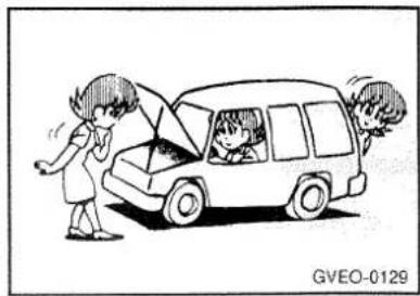
natural_image
Cartoon illustration of a car with two people interacting near the window, no text or symbols presentAdequate care of your vehicle at regular intervals serves to preserve the value and appearance as long as possible.
Some maintenance items can be carried out by the owner (do it yourself).
While others should be done only by a GALLOPER dealer (periodic inspection and maintenance). This section describes only those items which can be carried out by the owner. In the event a malfunction or other problem is discovered, have it corrected by a GALLOPER dealer. This section contains information on inspection maintenance procedures that you can do yourself, if you so desire. Follow the instructions and cautions for each of the various procedures.
CAUTION
- When checking or servicing the inside of the engine compartment, be sure the engine is stopped and has had a change to cool down.
- If it is necessary to do work in the engine compartment with the engine running, be especially careful that your clothing, hair, etc., does not become caught by the fan, V belts, or other moving parts.
- Improper handling of components and materials used in the vehicle can endanger your personal safety. Consult a GALLOPER dealer for necessary information.
Inspection items
(1) Engine oil
(2) Automatic transmission fluid *
(3) Engine coolant
(4) Battery
(5) Brake fluid
(6) Power steering fluid
(7) Clutch fluid (hydraulic clutch only)
(8) Washer fluid
(9) Wheel condition(including spare wheel)
(10) Tyre inflation pressure (including spare wheel)
(11) Fuel, engine coolant, oil, and exhaust gas leakage
(12) Exterior and interior lamp operation
(13) Meter, gauge, and indication/warning lamp operation
(14) Steering wheel free play
(15) Clutch pedal free play
(16) Brake pedal free play
(17) Parking brake lever stroke
Other
(1) Wheel rotation
Every 15,000km (9,000 miles) or 12 months, whichever comes first.
(2) Hinges and latches lubrication
NOTE
Points requiring routine inspection or replenishment such as the engine oil, coolant, brake fluid are marked white for easy identification.
Engine oil

All engines consume a certain amount of oil. It is important, therefore, to check the oil level at regular intervals or before starting a long trip.
This check must be made with the engine warm but not running. Park the vehicle on a level surface, stop the engine, and then wait a few moments to allow the engine oil in circulation to return to the oil pan to ensure accurate measurement. Remove the dipstick and wipe it with a clean cloth. Reinsert the dipstick as far as it goes. Remove the dipstick and read the oil level, which should always be within the range indicated in the figure. If the oil level is below the specified limit, remove the cap located on the cylinder head cover and add enough oil to raise the level to within the specified range. Be sure to use the specified engine oil and do not mix various types of oil. Also, avoid mixing different
Petrol-powered vehicles

bar
| Category | Value | |---|---| | 1 | -20 -5 15 32 50 70 85 105 120°F | -30 -20-10 0 10 20 30 40 50°C | | 2 | | | | | | | | | | | | | | | | | | | | | | | | | | | | | | | | | | | | | | | | | | | | | | | | | | | / | / / / / / / / / / / / / / / / / / / / / / / / / / / / / / / / / / / / / / / / / / / / / / / / / / / | | | | 1 | -20 -5 15 32 50 70 85 105 120°F | -30 -20-10 0 10 20 30 40 50°C | | 2 | -20 -5 15 32 50 70 85 105 120°F | -30 -20-10 0 10 20 30 40 50°C | | 2 | -20 -5 15 32 50 70 85 105 120°F | -30 -30 15 32 50 70 85 105 120°F | 2 | -20 -5 15 32 50 70 85 105 120°F | -30 -30 15 32 50 70 85 105 120°F | 2 | -20 -5 15 32 50 70 85 105 120°FDiesel-powered vehicles

makes of oil together if possible. After adding oil, close the cap securely.
Selection of engine oil
(1) Use engine oil conforming to the following API classification:
Gasoline-powered vehicle "FOR SERVICE SG" or higher Diesel-powered vehicle "FOR SERVICE CD" or higher
(2) Select engine oil of the proper SAE viscosity number according to the atmospheric temperature.
1 - Atmospheric temperature
2 - SAE viscosity No.
Automatic transmission fluid \*
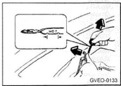
The proper amount of automatic transmission is essential to the life and operation of the automatic transmission. Either insufficient fluid or excessive fluid could cause transmission trouble. The transmission fluid filler port cap is equipped procedure to check the fluid lever.
(1) Check the fluid lever after the vehicle has been driven enough to warm up the transmission fluid.
(2) Park the vehicle on a flat, level surface and apply the parking brake.
(3) With the engine idling and the brake pedal fully depressed, move the transmission selector lever through all the position from "P" to "L", stopping momentarily at each position.
(4) Move the selector lever to "N"
(5) Remove the dipstick and wipe it with a clean, lint-free cloth.
(6) The fluid level should always be between the two marks on the dipstick.
"DIAMOND ATF SP-2" automatic transmission fluid should be used for replenishment.
CAUTION
Do not spill the fluid onto the exhaust manifold when it is inspected or added soon after driving. This will help avoid danger of fire.
Engine coolant

A translucent coolant reserve tank is located in the engine compartment. The coolant level in this tank should be kept: between the "LOW" and "FULL" marks when measured while the engine is warm and idling.
The cooling system is a closed system and normally the loss of coolant should be very slight. A noticeable drop in the coolant level could indicate leakage. If this occurs, have the system checked at a GALLOPER dealer as soon as possible.
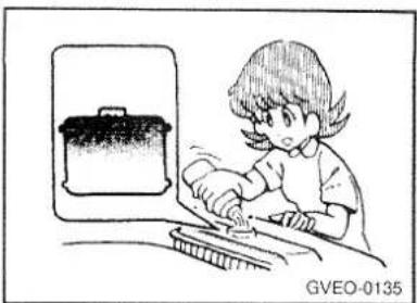
natural_image
Illustration of a child washing hands with a small pot nearby (no text or symbols)If the level should drop below the "LOW" level on the reserve tank, open the lid and add coolant. Also, if the reserve tank is completely empty, remove the radiator cap and add coolant until the level reaches the filler neck.

natural_image
Cartoon illustration of a person reacting to a large explosion or smoke, with smoke rising and falling (no text or symbols)CAUTION
Do not open the reserve tank lid or radiator cap while the engine is hot.
The coolant system is under pressure and any hot coolant escaping could cause severe burns.
Antifreeze
The engine coolant contains an ethylene glycol anticorrosion agent. The cylinder head and coolant pump housing are cast aluminum alloy, and periodic changing of the engine coolant is necessary to prevent corrosion of these parts.
Because of the necessity of this anticorrosion agent, the coolant must not be replaced with plain water even in summer. The required concentration of antifreeze differs depending on the expected ambient temperature.
| Minimum ambient temperature | -10°C | -20°C | -30°C | -45°C |
| Antifreeze concentration | 30% | 40% | 50% | 60% |
CAUTION
For effective anticorrosion and antifreeze performance, keep the antifreeze concentration within the range of 30 to 60%. Concentrations exceeding 60% will result in a reduction of cooling performance, thus adversely affecting the engine.
Battery

natural_image
Simple line drawing of a battery with a coiled cable and two connectors, no text or symbols present.The condition of the battery is very important for quick starting of the engine and proper functioning of the vehicle's electrical system. Regular inspection and care are especially important in cold weather.
Checking battery electrolyte level

natural_image
Simple line drawing of a hand inserting a plug into a battery (no text or symbols)The electrolyte level must be between the "UPPER" and "LOWER" marks stamped on the outside of the battery.
Replenish with distilled water as necessary. The inside of the battery is divided into several compartments; remove the cap from each compartment and fill to the "UPPER" mark.
Do not over replenish beyond the "UPPER" mark because spillage during driving could cause damage.
Check the electrolyte level at least once depending on the operating conditions.
If the battery is not used, it will discharge by itself with time. Check it once every four weeks and charge with low current as necessary.
Disconnection and connection
Never disconnect the battery while the engine is running; doing so could damage the vehicle's electrical components. First disconnect the negative terminal and then the positive terminal. When connecting the battery, first connect the positive terminal and then the negative terminal.
CAUTION
- Keep the terminals clean. After the battery is connected, apply terminal protection grease. To clean the terminals, use lukewarm water.
- Never short circuit the battery; doing so could cause it to overheat and be damaged.
- Do not smoke or bring an open flame near the battery; doing so could ignite the explosive gas generated by the battery.
- The battery electrolyte is extremely caustic. Do not allow it to come in contact with your eyes, skin, clothing, or the painted surfaces of the vehicle. Spilled electrolyte should be flushed immediately with ample amounts of water. Irritation to eyes or skin from contact with electrolyte requires immediate medical attention.
-
If the battery is to be quick charged, first disconnect the battery cables.
-
In order to prevent a short circuit, be sure to disconnect the negative (-) terminal before doing anything else.
- Keep it out of the reach of children.
Brake fluid

Check the brake fluid level in the reservoir. The brake fluid level must be between the "MAX" and "MIN" marks on the reservoir. The fluid level falls slightly with wear of the brake pads, but this does not indicate any abnormality. If the brake fluid level falls markedly in a short length of time, it indicates leaks from the brake equipment. If this occurs, have the vehicle checked at a GALLOPER dealer. Use SAE J1703(or DOT3) or equivalent type brake fluid. The brake fluid is hygroscopic. Too much moisture in the brake fluid will adversely affect the brake equipment, reducing the brake performance. In addition, the brake fluid reservoir is equipped with a special cap to prevent the entrance of air, and this cap should not be removed.
On a vehicle with a brake fluid warning lamp, brake fluid level is monitored by a float. When the brake fluid level falls below the "MIN" mark, the brake fluid warning lamp lights up.
CAUTION
(1) Use only the specified brake fluid. Also, the additives in different brands may result in a chemical reaction when mixed together, so avoid mixing different brands if possible.
(2) Brake fluid is toxic and corrosive.
Power steering fluid

natural_image
Diagram of a mechanical device with a lever and handle, no visible text or symbolsCheck the fluid level in the reservoir while the engine is idling. Unscrew the reservoir cap; the level gauge is attached to the bottom of the cap.

natural_image
Illustration of a child using a tool to measure a mechanical component, with an inset showing the magnified view (no text or symbols)The level should be between the "MAX" and "MIN" lines on the level gauge. Use "DEXRON II" or equivalent.
Hydraulic clutch
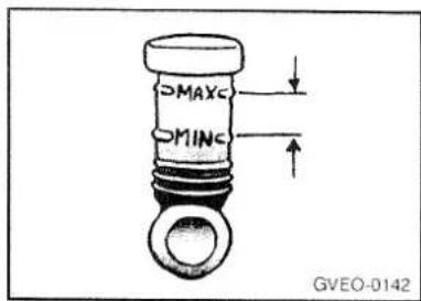
The clutch fluid reservoir is located at the rear of the engine compartment. The fluid level should always be between the "MAX" and "MIN" marks on the reservoir. Use only SAE J 1703(or DOT3) brake fluid.
Washer fluid
Windscreen washer fluid

natural_image
Simple line drawing of a child sitting at a desk, holding an object (no text or symbols)Check the washer fluid level in the container inside the engine compartment. If the level is low, replenish the container with washer fluid.
Rear window washer fluid

natural_image
Illustration of a child in bed with an inset showing a medical device (no text or symbols present)Remove the lid from the top of the inside wheelhouse.
Check the washer fluid level in the container. If the level is low, replenish the container with washer fluid.
Wheel condition
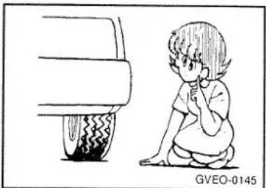
natural_image
Illustration of a child sitting next to a car tire, no text or symbols presentCheck the tyres for cuts, cracks and other damage. Replace the tyres if there are deep cuts or cracks. Also check each tyre for pieces of metal or pebbles.
The use of worn tyres can be very dangerous because of the greater chance of skidding or hydroplaning. The tread depth of the tyres must exceed 1.6mm (0.06in.) in order for the tyres to meet the minimum requirement for use.

If there are belt-line wear indicators on the tyres, they will appear in six places on the surface of the tyre wears, thereby indicating that the tyre no longer meets the minimum requirement for use. When these wear indicators appear, the tyres must be replaced with new ones. Confirm that the wheel nuts are tightened sufficiently. Refer to the section of this manual entitled "Wheels" for information concerning replacement of the tyres.
Fuel, engine coolant, oil, and exhaust gas leakage
Look under the body of your vehicle to check for fuel, engine coolant, oil, and exhaust gas leaks. If leaks are evident, take your vehicle to a GALLOPER dealer for inspection.
Exterior and interior lamp operation
Operate the light switch and combination switch to confirm that all lamps are functioning properly.
If the lamps do not go on, the probable cause is a blown fuse or defective lamp bulb. Check the fuses first. If there is no blown fuse, check the lamp bulbs.
For information regarding the inspection and replacement of the fuses, refer to the section entitled "Emergency measures" If the fuses and bulbs are all OK, take the vehicle to a GALLOPER dealer for inspection.
Headlight washer fluid \* (If installed)

natural_image
Simple line drawing of a child sitting at a desk, holding an object (no text or symbols)Check the headlight washer fluid level in the container inside the engine compartment.
If the level is low, replenish the container with washer fluid.
Check the condition of the spray nozzles periodically.
Tyre inflation pressure
| Tyre size | Pressure Kg/cm2 (lb/in2) |
| P215/75R15FrontRear | 1.8(26)2.3(33) |
| P235/75R15FrontRear | 1.8(26)2.0(29) |
| P265/70R15FrontRear | 1.8(26)2.0(29) |
| LT235/75R15FrontRear | 2.7(38)3.1(44) |
| P275/60R15FrontRear | 1.8(26)2.0(29) |
Check the tyre inflation pressure of all the tyres while they are cold; if insufficient or excessive, adjust to the specified value. After the tyres inflation pressure has been adjusted, check the tyres for damage and air leaks.
Be sure to put rubber caps on the valves.
Meter, gauge, and indication/warning lamp operation
Run the engine to check the operation of all meters, gauges, and indication/ warning lamps.
If there is anything wrong, take the vehicle to a GALLOPER dealer for inspection.
Steering wheel free play
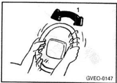
natural_image
Illustration of hands holding a device with a device labeled '1' above it, no text or symbols present.Check the free play of the steering wheel by moving it slightly in each direction (from the straight ahead position) until resistance is felt.
On vehicle equipped with a power steering, check the steering wheel free play while the engine is idling.
The free play at the circumference should not exceed the standard value.
1 - free play 50 mm (2 in.)
If the steering wheel free play exceeds the standard value, have the steering wheel adjusted at a GALLOPER dealer.
Clutch pedal free play

natural_image
Illustration of a hand holding a tool with an arrow indicating direction, no text or symbols presentPress down on the clutch pedal with your fingers until initial resistance is felt. This distance should be within the specified range.
1 - Free play 6 to 13mm (0.1 to 0.5in.)
If the clutch pedal free play is not within the standard range, have the clutch pedal adjusted at a GALLOPER dealer.
Brake pedal free play

natural_image
Illustration of a hand holding a tool with an arrow indicating direction, no text or symbols presentStop the engine, depress the brake pedal several times, and then press down on the pedal with your fingers until initial resistance is felt. This distance should be within the specified range.
1 - free play
3 to 8mm(0.1to 0.3in)
If the brake pedal free play is not within the standard range, have the brake pedal adjusted at a GALLOPER dealer.
Parking brake lever stroke

natural_image
Illustration of a hand holding a tool with an arrow indicating motion (no text or symbols)Pull the parking brake lever all the way up to check the number of "clicks" that the ratchet makes. One click represents a lever movement of one notch.
The lever should move the specified number of notches for normal brake application.
Parking brake lever stroke: 4 to 6 notches
If the parking brake lever stroke is not within the standard value range, have the brake lever adjusted at a GALLOPER dealer.
Wheel rotation

Tyres tend to wear unevenly over a long period of service. To make sure that the tyres wear evenly as possible and for longer tyre life, rotate the wheels in the sequence illustrated.
Bring the vehicle to a GALLOPER dealer to have the balance of the wheels properly adjusted.
CAUTION
If the spare wheel is of a different type from the other four wheels, the four wheel rotation method (excluding the spare wheel) should be used.
Hinges and latches lubrication
Check all latches and hinges and lubricate if necessary by first cleaning and then applying multipurpose grease.
MEMO
Emergency measures
Tools and jack
Jack
Jacking up the vehicle
Spare wheel
If tyre is punctured
Towing
Engine overheating
Bleeding the fuel system
(diesel-powered vehicles only)
Removal of water from the fuel filter
(diesel powered vehicles only)
Emergency starting
Brake pad wear alarm
Fuses
Tools and jack

The storage location of the tools and jack should be remembered in case of a sudden need.
Location
1 - Tools
2 - Jack
3 - Jack handle
Tools

1 - tool bag
2 - Wrench
3 - Pliers
4 - Screwdriver
5 - Wheel nut wrench
6 - Bar
Jack
To remove (Short wheel based models)

natural_image
Line drawing of a car interior showing a hand holding a tool, with no visible text or symbols.Open the lid.
To remove (Long wheel based models)

natural_image
Diagram of a car's seatbelt mechanism with a hand adjusting the seatbelt (no text or symbols present)Open the lid.
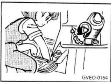
natural_image
Illustration of a child using a sewing machine (no text or symbols visible)
natural_image
Illustration of a person using a tool on a vehicle, with an inset showing a car component (no text or symbols)Remove the securing nut, and then take out the jack.
Jacking up the vehicle
The method for jacking up the vehicle should be remembered in order to change a tyre in the event of a puncture and in order to install tyre chains. After stopping the engine and applying the parking brake on a flat, level surface, also use chocks to hold the wheels.
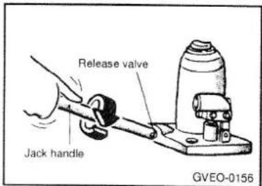
Take out the jack and jack handle. Using the jack handle, turn the release valve clockwise until it reaches a stop.

The fit the jack handle into the holder, and align the groove of the jack handle with the notch of the holder.
Move the jack handle up and down to raise the ram until just before the jack contacts the jacking point of the vehicle.

Position the jack with the jack handle.
Position it only at the specified points indicated in the illustration; use of the jack at other points could damage the vehicle body.
Moving the jack handle up and down, raise the piston.
NOTE
To jack up the front of the vehicle, normally position the jack at location A; however, if the ground clearance is insufficient at location A, use location B.
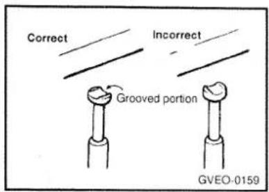
When jacking up the rear of the vehicle, turn the tip of the jack so that the grooved portion properly meets the designated point. Using the jack handle, turn the release valve counterclockwise slowly to lower the ram, and then take out the jack.

NOTE
(1) Occasionally when the front part of the vehicle is jacked up, the grooved portion of the designated point will not come off. When this happens, rock the vehicle to lower the ram.
(2) When the jack is difficult to remove by hand, insert the jack handle into the holder and catch the jack handle notch onto the holder notch and secure it there. Then pull the jack handle and remove the jack.
Press the piston down all the way, and turn the release valve clockwise as far as possible.
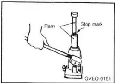
CAUTION
(1) Use only the jack included with the vehicle and use it only for changing a wheel and for installing tyre chains.
(2) Position the jack on a hard, level surface.
(3) If the release valve is loosened by turning it 2 or more times in the counterclockwise direction, the jack's oil will leak and the jack cannot be used.
(4) This jack is hydraulic, and the ram is a two stage type. When both rams are raised and the stop mark of the upper ram becomes visible, stop jacking immediately.
(5) Some models are equipped with jacks which have no stop mark. To extend this type of jack to its full length, continue jacking until the

jack stops and can be extended no further.
(6) When jacking up the vehicle, be sure that there is no one in or under the vehicle.
(7) When jacking up the vehicle, do so only until the tyres are slightly lifted from the ground. It is dangerous to jack up the vehicle more than that much.
(8) It is very dangerous if the jack somehow slips, so never leave the vehicle in the jacked up position, and never shake the vehicle while it is raised.
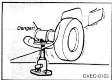
(9) When jacking up one side of a vehicle with limited differential, do not start the engine. The power of the engine could be transferred to the tyres that are still in contact with the ground and cause the vehicle to move.
Spare wheel

Check the air pressure of the spare tyre frequently and make sure it is ready for emergency use at any time.
Maintaining the spare wheel at the highest specified air pressure will ensure that it can always be used under any conditions (city/high speed driving, varying load weight, etc.) The spare wheel is stored on the outside of the back door. To remove the spare wheel, loosen the nuts securing it to the door with the wheel nut wrench. To prevent theft, in some models one of the spare wheel nuts is a lock nut.

natural_image
Illustration of a child using a tool to adjust or watch a car tire (no text or symbols visible)To remove the lock nut, insert the ignition key into the lock cylinder, pulling the nut cover with the key still in it toward you and off. Then loosen the spare wheel nuts with the wheel nut wrench.
To reinstall the lock nut, replace the nut cover with the key still in the lock cylinder, pressing the nut cover onto the lock nut as far as it will go then lock it by removing the key.
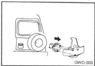
natural_image
Diagram showing a car interior with a wheel and a seatbelt, connected by an arrow indicating motion (no text or symbols)To remove the spare wheel, loosen the wheel cover, the wheel cover bracket and the nuts securing it to the door with the wheel nut wrench. To prevent theft, in solne models one of the spare wheel nuts is a lock nut.
If a tyre is punctured
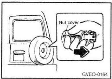
To remove the lock unt, insert the ignition key into the lock cylinder, pulling the nut cover with the key still in it toward you and off. Then loosen the spare wheel nuts with the wheel unt wrench.
To reinstall the lock nut, replace the nut cover with the key still in the lock cylinder, pressing the unt cover onto the lock nut as far as it will go then lock it by removing the key.
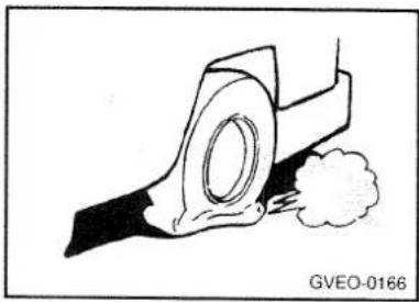
natural_image
Technical line drawing of a mechanical component with a circular feature and smoke, labeled GVEO-0166 (no text or symbols on the diagram itself)If a tyre must be changed due to a puncture, do so only after first following every precaution for safety: parking the vehicle in a place where it is not a traffic hazard or dangerous to you and your vehicle's occupants, on a flat surface, and in such a why that you will not be injured by any part of the vehicle while changing the tyre.

natural_image
Cartoon illustration of a car crashing under a traffic jam, with no visible text or symbols(1) Comply with local regulations concerning the protection of broken down vehicle by switching on the hazard warning lamp and setting up a warning triangle flashing signal lamp, etc., at a adequate distance from the vehicle. Others in the vehicle should get out of the vehicle and wait in a safe place.
CAUTION
The spare wheel should always be securely in position.
If a flat tyre is changed, put the flat tyre in the spare wheel mounting position, and use the wheel nut wrench to secure it firmly.
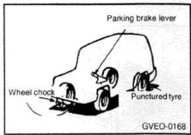
(2) Position the vehicle on a flat, hard surface and apply the parking brake. To prevent the vehicle from rolling when it is raised on the jack, chock the wheel diagonally opposite to the one to be changed.
(3) Prepare the spare wheel, jack and wheel nut wrench.

(4) The spare tyre should be placed, for safety, under the vehicle and near the jack for convenient access when ready to be mounted.

(5) If the vehicle is equipped with wheel caps, use the wheel cap wrench or the wheel nut wrench to remove the cap from the wheel.
NOTE
Use a piece of cloth or other similar material to prevent scratching the wheel when the wheel cap wrench or wheel nut wrench is used.
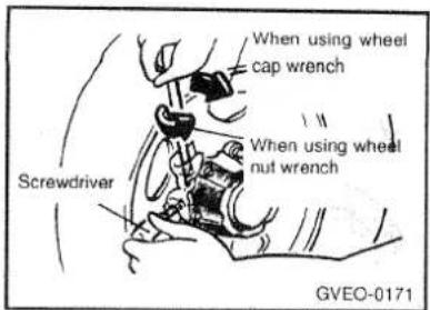
For vehicles with manual free-wheel hubs, remove the wheel caps as described below.
(a) Move the wheel cap wrench or wheel nut wrench as shown in the figure so as to slightly lift the wheel cap so that there is a space. Insert a screwdriver in this space.
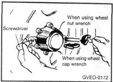
(b) Remove the wheel cap wrench or wheel nut wrench and use it at the opposite side.
(c) Move each tool as shown in the figure so as to remove the wheel cap.

(6) Loosen the wheel nuts with the wheel nut wrench. Do not remove the wheel nuts yet.

natural_image
Illustration of a child using a tool near a vehicle (no text or symbols)(7) Refer to the section entitled "Jacking up the vehicle" to select a jacking point near the flat tyre at which to position the jack, and then raise the vehicle until the tyre is slightly off the ground. Remove the wheel nuts.

(8) For a front wheel, remove the tyre and wheel as follows.
(a) Pull the lower part of the disc wheel toward you.
(b) While holding the disc wheel up, lift it up and over the tab of the wheel cap mounting fixture, and remove it upward.

CAUTION
Be careful not to pull a disc wheel straight off, because to do so may damage the tab of the centre cap mounting fixture. For a rear wheel, remove the centre cap mounting fixture from the disc wheel.
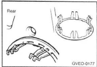
(9) Use the following procedure to mount the centre cap mounting fixtures: For the front wheels, align any one of the three projections on the inside of the mounting fixture with a bolt position, and then mount the fixture onto the hub, being careful not to widen the opening. For the rear wheels, align any one of the three projections on the inside of the mounting fixture with a wheel mounting hole, and then mount the fixture securely onto the disc wheel from the inside of the wheel.
CAUTION
Note that the shapes of the mounting fixtures for the front wheels and those for the rear wheels are different.
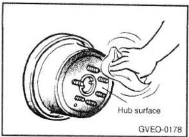
(10) Clean away any mud, etc. on the hub surface or in the installation holes in the wheel, and then mount the spare tyre.

(11) With the tapered side of the wheel nuts facing toward the wheel (see illustration), screw the nuts onto the bolt and tighten all the way by hand, to the extent that the wheel is not loose.
CAUTION
Never put oil on the wheel bolts or nuts, because this may cause them to become loose.

(12) Lower the vehicle slowly and then alternately tighten the nuts until each nut has been tightened to the specified torque. Tightening torque 10 to 12 kgm (100 to 120 Nm, 72 to 87 ft. lbs.)
CAUTION
When tightening the wheel nuts, do not apply excessive force to tighten them, such as by using your foot to apply force to the wheel nut wrench, or by using a pipe or similar tool.

(13) Remove the chock from the wheel.
(14) Tap in the centre caps with your hand.
(15) The flat tyre should be repaired and balanced as soon as possible.
(16) After the spare tyre is once again replaced by the original tyre, adjust the inflation pressure to the correct specification.
Towing

As shown in the illustration, the towing hooks are located at their right side of the frame (at the front) and at the centre (at the rear).
Using any part other than the designated towing hooks could result in damage to vehicle body.
The regulations concerning towing may differ from country to country. It is recommended that you obey the regulation of the country where you are driving your vehicle. If your vehicle is to be towed, pay careful attention to the following points.

- For vehicles with manual transmission, move the gearshift lever to neutral and the transfer shift lever to the "N" position so as to unlock the free-wheeling hubs.
For vehicles with automatic transmission, move the selector lever to the +N+ position.
-
Be sure the towing speed is within the legal limit. Also, vehicles with automatic transmission should never be towed at speeds excess of 30km/h(18mph) or for distance greater than 30km(18miles).
-
Turn the ignition switch to "ACC" to unlock the steering wheel. If you will be using the turn signals while being towed, turn the ignition switch to the "ON" position.
-
Turn on the hazard warning lamps.
- During towing, make sure that close contact is maintained between the drivers of both vehicles, and that the vehicles travel at low speed. Avoid abrupt starting or stopping which might subject the vehicles to shock.
- If the transmission is malfunctioning or damaged, must be towed farther than 30 km(18miles), tow the vehicle with the rear wheels raised off the ground.
- As the vehicle is equipped with a brake booster system, the brake boosting power will be lost and greater force will be required to depress the brake pedal.
- If the vehicle is equipped with a power steering system, greater force will be required to operate the steering wheel.
NOTE
Your vehicle should only be used to tow another vehicle if the weight of the other vehicle is the same as or less than that of your vehicle.
CAUTION
To prevent entry of exhaust gas from the towing vehicle, set the air selection lever on the heater control to the recirculation position.
Engine overheating

If the water temperature gauge indication remains in the red zone for a long time, the engine may be overheated. If this occurs, take the following corrective measures:
- Stop the vehicle in a safe place.
- With the engine still running, raise the bonnet to ventilate the engine compartment.
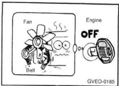
Confirm that the radiator fan is turning. If the fan is not turning, stop the engine immediately and contact a GALLOPER dealer for assistance.
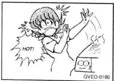
Take care, when opening the bonnet, not to be injured if the bonnet or its support rod is hot, or by escaping hot water or steam.
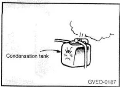
Be careful not to be burned by steam escaping from the condensation tank cap.
- After the engine coolant temperature has dropped, stop the engine.
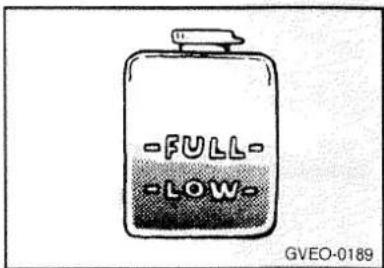
- Check the coolant level in the reserve tank. If there is none, make sure that the engine has cooled down before removing the radiator cap, because hot steam or boiling water otherwise will gush from the filler port and may scald you.

natural_image
Illustration of a child using a tool on a table with a pot nearby (no text or symbols)Add coolant to the radiator and/or reserve tank if necessary (refer to the "Do it yourself" section). Adding cold water rapidly when the engine is hot could cause the cylinder head and/or block to crack, so be sure to add the water a little at a time while running the engine.
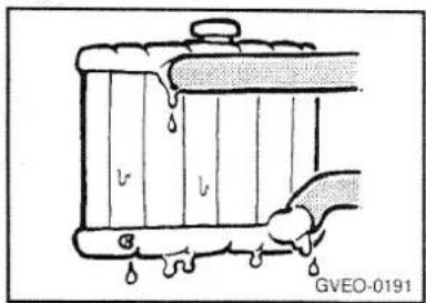
- Examine the radiator hoses for coolant leakage and the V belt for looseness or damage. If there is anything wrong with the cooling system or V belt, have the problem corrected at a GALLOPER dealer.
Bleeding the fuel system (diesel-powered vehicles only)

The fuel system should be bled to remove air as described below if the fuel supply is exhausted during travel.
1. Loosen the air plug at the top of the fuel filter.

- Pump the hand pump until there are no more bubbles in the fuel coming out of the air plug. When doing this, place a cloth around the air plug to prevent the escaping fuel from spewing about.
- Tighten the air plug when there are no more bubbles in the fuel.
- Continue pumping until the hand pump becomes stiff.
- Finally, check to be sure that there is no leakage of fuel. If in doubt, consult your nearest GALLOPER dealer.
CAUTION
(1) Do not smoke or have any other open flame near the vehicle while bleeding the fuel system.
(2) Be sure to carefully wipe up any water drained out in this manner, because the fuel mixed in the water might be ignited and result in a fire.
Removal of water from the fuel filter (diesel-powered vehicles only)
If the warning lamp illuminates during driving, it indicates that water has accumulated in the fuel filter. If this occurs, remove the water as described below.

- Rotate the drain plug at the bottom of the fuel filter.
- Operate the hand pump slowly 6 or 7 times in order to force the water out through the drain plug.
- Rotate the drain plug when water no longer comes out.
-
Loosen the air plug and bleed the air. (Refer to "Bleeding the fuel system".)
-
Check to be sure that the warning lamp illuminates when the ignition key is turned to "ON", and that it goes off when the engine is started. If in doubt, consult your nearest GALLOPER dealer.
CAUTION
(1) Do not smoke or have any other open flame near the vehicle while bleeding the fuel system.
(2) Be sure to carefully wipe up any water drained out in this manner, because the fuel mixed in the water might be ignited and result in a fire.
Emergency starting
If the engine cannot be started because the battery is weak or dead, the battery from another vehicle can be used with jumper cables to start the engine.
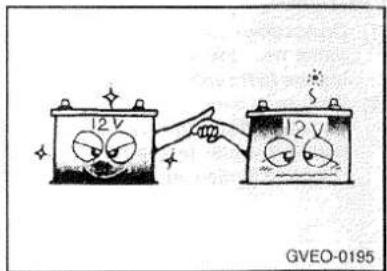
CAUTION
- Do not attempt to start the engine by pulling or pushing the vehicle.
- Use only specified jumper cables with sufficient cross-sectional area.
The following points should be observed:
- Both batteries must be 12V. The capacity(Ah) of the battery supplying current should not be significantly below that of the discharged battery.
- Use only heavy-duty jumper cables.
- A discharged battery can freeze. A frozen battery must be thawed out before connecting the jumper cables.
- There should be no contact between the two vehicles; otherwise current may flow when the positive terminal is connected.
- The discharged battery must be correctly connected to the vehicle electrical system.
- Run the engine of vehicle supplying current.

- Connect the jumper cables as follows:
(1) Connect one end of one jumper cable to the positive terminal of the flat battery, and the other end to the positive terminal of the booster battery.
(2) Connect one end of the other jumper cable to the negative terminal of the booster battery, and the other end to the engine block of the vehicle with the flat battery at the point farthest from the battery.

CAUTION
(1) Do not allow the jumper cable clips to touch one another.
(2) Do not connect the jumper cable to the negative terminal of the flat battery. The battery generates explosive gas, and a spark caused when the jumper cable is disconnected from the negative terminal could ignite this gas and cause an explosion.
(3) Be careful that the jumper cable does not become caught in the cooling fan, etc.

- Start engine as described in "Starting the engine".
- After the engine is started, disconnect the cables in the reverse order.
Brake pad wear alarm

natural_image
Cartoon illustration of a person waving beside a car at a garage (no text or symbols)The disc brakes are provided with an alarm device which produces a metallic frictional sound (squeal) while driving when the brake pads have worn down near to the service-able limit.
If such a sound is produced, have the brake pads replaced at a GALLOPER dealer.
Fuses

natural_image
Illustration of a person using a computer with a magnified view showing a hand holding a device (no text or symbols present)To prevent damage to the electrical system due to short-circuit or overloading, each individual current circuit is provided with a fuse.
The fuse housing is located on the side of the instrument panel on the driver's side shown in the illustration.
Changing a fuse


- Before replacing a fuse, be sure to turn off the electrical system concerned.
- Remove the fuse housing cover.
-
Referring to the fuse load capacity table, check the fuse pertaining to the problem.
-
Replace the fuse if necessary. There is a fuse puller in the fuse housing (inside the vehicle). First pull the fuse puller out of the fuse housing and then, as shown in the illustration, pull the fuse straight out from the fuse housing. If it is not blown, something else must be causing the problem; contact a GALLOPER dealer to have the problem checked.
- Insert a new fuse of the same capacity securely into the clip.
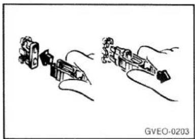
natural_image
Diagram showing two mechanical components with wires, no text or symbols presentCAUTION
(1) If the newly inserted fuse blows again after a short time, have the electrical system checked by a GALLOPER dealer to find the cause of the short circuit and rectify it.
(2) Never use a fuse with a capacity larger than that specified or any substitute such as wire, foil, etc.; doing so will cause the circuit wiring to heat up and could cause a fire.
Things you should know
Chassis number
Vehicle identification number
Engine number
Chassis number
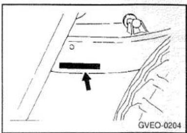
natural_image
Diagram showing a person standing near a vehicle with an arrow pointing to a horizontal bar, labeled GVEO-0204 (no text or symbols on the diagram itself)The chassis number is stamped on the side of the frame near the right rear wheel.
Vehicle identification number (VIN)

natural_image
Technical line drawing of a mechanical assembly with no visible text or symbolsThe vehicle identification code plate is riveted as illustrated.
The plate shows model code, vehicle ID. NO. (VIN) and body color code, etc.
Engine number

The engine number is stamped on the engine cylinder block as shown in the illustration.
Service data
Scheduled maintenance table
Specifications
Lubrication chart
SCHEDULED MAINTENANCE TABLE
The following maintenance services must be performed to assure good vehicle control and performance. Keep receipts for all vehicle services to protect your warranty. Where both mileage and time are shown, the frequency of service is determined by whichever occurs first.
R : Replace I : Inspect and, after inspection, clean, adjust, repair or replace if necessary
| NO. | DESCRIPTION | KILOMETERS X 1000 | 7.5 | 15 | 30 | 45 | 60 | 75 | 90 | 105 | 120 |
| MONTHS | 6 | 12 | 24 | 36 | 48 | 60 | 72 | 84 | 96 | ||
| ENGINE CONTROL SYSTEM MAINTENANCE (DIESEL) | |||||||||||
| 1 | ENGINE OIL & OIL FILTER | SEE NOTE (1) | |||||||||
| 2 | AIR CLEANER FILTER | I | R | I | R | I | R | I | R | ||
| 3 | FUEL SYSTEM LEAKS | I | I | I | I | I | I | I | I | ||
| 4 | FUEL FILTER | R | R | R | R | ||||||
| 5 | VALVE CLEARANCE | I | I | I | I | I | I | I | I | ||
| 6 | INJECTION TIMING | I | I | I | I | ||||||
| 7 | TIMING BELT | I | R | ||||||||
| 8 | DRIVE BELT(FOR WATER PUMP/ALTERNATOR) | I | I | I | R | I | I | I | R | ||
| 9 | ENGINE IDLE SPEED | I | I | I | I | I | I | I | I | ||
| 10 | INJECTION NOZZLE(IF EXHAUST GAS INCLUDES BLACK SMOKE) | I | I | I | I | ||||||
Note: (1) Replace the engine oil every 7,500 km or 6 months whichever occurs first after first replacement of 7,500 km.
R : Replace I : Inspect and, after inspection, clean, adjust, repair or replace if necessary
| NO. | DESCRIPTION | KILOMETERS X 1000 | 15 | 30 | 45 | 60 | 75 | 90 | 105 | 120 |
| MONTHS | 12 | 24 | 36 | 48 | 60 | 72 | 84 | 96 | ||
| ENGINE CONTROL SYSTEM MAINTENANCE (GASOLINE) | ||||||||||
| 1 | ENGINE OIL & FILTER | Every 10,000Km : "R" | ||||||||
| 2 | DRIVE BELT (ALT, W/PUMP, P/STRG) | I | R | I | R | |||||
| 3 | FUEL FILTER | R | R | |||||||
| 4 | FUEL LINES, FUEL HOSES & CONNECTIONS | I | I | I | I | I | I | I | I | |
| 5 | TIMING BELT | I | R | |||||||
| 6 | VAPOR HOSE & FUEL FILLER CAP | I | I | I | I | |||||
| 7 | VACUUM CRANKCASE VENTILATION HOSES | I | I | I | I | |||||
| 8 | AIR CLEANER FILTER | I | R | I | R | I | R | I | R | |
| 9 | SPARK PLUGS | I | R | I | R | I | ||||
| SPARK PLUGS (PLATINUM COATED, 3.0L ONLY) | R | |||||||||
R : Replace I : Inspect and, after inspection, clean, adjust, repair or replace if necessary
| NO. | DESCRIPTION | KILOMETERS X 1000 | 7.5 | 15 | 30 | 45 | 60 | 75 | 90 | 105 | 120 |
| MONTHS | 6 | 12 | 24 | 36 | 48 | 60 | 72 | 84 | 96 | ||
| GENERAL MAINTENANCE | |||||||||||
| 1 | ENGINE COOLANT | SEE NOTE (2) | |||||||||
| 2 | MANUAL TRANSMISSION OIL | R | I | I | R | I | I | R | I | I | |
| 3 | AUTOMATIC TRANSMISSION OIL | R | R | ||||||||
| 4 | REAR AXLE OIL(WITH LSD) | R | I | I | R | I | I | R | I | I | |
| 5 | CLUTCH/BRAKE PEDAL FREEPLAY | I | I | I | I | I | I | I | I | ||
| 6 | CLUTCH/BRAKE OIL RESERVOIR | I | I | I | I | I | I | I | I | ||
| 7 | BRAKE HYDRAULIC FLUID | R | R | R | R | ||||||
| 8 | FRONT BRAKE PAD | I | I | I | I | I | I | I | I | ||
| 9 | FRONT BRAKE CALIPERS/CYLINDERS/DISC | I | I | I | I | I | I | I | I | ||
| 10 | REAR BRAKE DRUMS/LININGS/CYLINDERS | I | I | I | I | I | I | I | I | ||
| 11 | HAND BRAKE | I | I | I | I | I | I | I | I | ||
| 12 | TIRE CONDITION/PRESSURE | Temporary check and correction according to the condition | |||||||||
| 13 | EXHAUST SYSTEM/MOUNTING | I | I | I | I | I | I | I | I | ||
| 14 | STEERING JOINT/RACK/BOX/OIL LEAKS | I | I | I | I | I | I | I | I | ||
| 15 | SUSPENSION JOINT/SEATS | I | I | I | I | I | I | I | I | ||
| 16 | FRONT WHEEL BEARING | I | I | I | I | I | I | I | I | ||
| 17 | ENGINE COOLANT HOSES | I | I | I | I | I | I | I | I | ||
| 18 | BRAKE PIPE CORROSION | I | I | I | I | I | I | I | I | ||
Note: (2) For every 24 months : "R"
MAINTENANCE UNDER SEVERE USAGE CONDITIONS
The following items must be serviced more frequently on cars normally used under severe driving conditions. Refer to the chart below for the appropriate maintenance intervals.
R : Replace I : Inspect and, after inspection, clean, adjust, repair or replace if necessary
| MAINTENANCE ITEM | MAINTENANCE OPERATION | MAINTENANCE INTERVALS | DRIVING CONDITION | |
| ENGINE OIL AND FILTER | R | GASOLINE | DIESEL | A, B, C, F, H |
| EVERY 5,000 KM OR 3MONTHS | EVERY 3,000 KM (GENERAL EXPORT) EVERY 4,000 KM (EU, EASTERN EUROPE, CIS, ISRAEL) | |||
| AIR CLEANER FILTER | R | MORE FREQUENTLY | C, E | |
| SPARK PLUGS | R | MORE FREQUENTLY | B, H | |
| TIMING BELT | R | EVERY 60,000 KM OR 48 MONTHS | D, E, F, G | |
| BRAKE PADS, CALIPERS AND ROTORS | I | MORE FREQUENTLY | C, D, G, H | |
| REAR BRAKE DRUMS/LININGS, PARKING BRAKE | I | MORE FREQUENTLY | C, D, G, H | |
| STEERING GEAR RACK, LINKAGE & BOOTS/LOWER ARM BALL JOINT | I | MORE FREQUENTLY | C, D, E, F | |
SEVERE DRIVING CONDITIONS
A - Repeated short distance driving
B - Extensive idling
C - Driving in dusty, rough roads
D - Driving in areas using salt or other corrosive materials or in very cold weather
E - Driving in sandy areas
F - More than 50% driving in heavy city traffic during hot weather above 32°C (90°F)
G - Driving in mountainous areas
H - Towing a trailer
Specifications
| Engine | |
| Type | |
| 2.5NA | D4BA |
| 2.5T/C | D4BF |
| 3.0GSL | G6AT |
| 2.6GSL | 4G54 |
| 2.5 INTERCOOLER T/C | D4BH |
| Piston displacement (cc) | |
| D4BA | 2,476 |
| D4BF | 2,476 |
| D4BH | 2,476 |
| G6AT | 2,972 |
| 4G54 | 2,555 |
| Bore X Stroke (mm) | |
| D4BA | 91.1 X 95 |
| D4BF | 91.1 X 95 |
| D4BH | 91.1 X 95 |
| G6AT | 91.1 X 76 |
| 4G54 | 91.4 X 98 |
| Compression | |
| D4BA | 21 |
| D4BF | 21 |
| D4BH | 21 |
| G6AT | 8.9 |
| 4G54 | 8.8 |
| Firing order | |
| D4BA | 1-3-4-2 |
| D4BF | 1-3-4-2 |
| D4BH | 1-3-4-2 |
| G6AT | 1-2-3-4-5-6 |
| 4G54 | 1-3-4-2 |
| Lubrication | |
| Oil pump type | |
| D4BA | Rotor |
| D4BH | Rotor |
| D4BF | Rotor |
| G6AT | Rotor |
| 4G54 | |
| Oil quantity (l) | |
| D4BA | 6.5 |
| D4BF | 6.5 |
| D4BH | 6.5 |
| G6AT | 4.7 |
| 4G54 | 4.9 |
| Fuel system | |
| Fuel tank capacity (l) | |
| D4BA(SWB) | 60 |
| (LWB) | 92 |
| D4BF(SWB) | 60 |
| (LWB) | 92 |
| D4BH(SWB) | 75 |
| (LWB) | 92 |
| G6AT(SWB) | 75 |
| (LWB) | 92 |
| 4G54(LWB) | 92 |
| Clutch | |
| Type | |
| D4BA | Dry single disc |
| D4BF | Dry single disc |
| D4BH | Dry single disc |
| G6AT | Dry single disc |
| 4G54 | Dry single disc |
| Operation type | |
| D4BA | Oil pressure type |
| D4BF | Oil pressure type |
| D4BH | Oil pressure type |
| G6AT | Oil pressure type |
| 4G54 | Oil pressure type |
| Transmission | |
| Type | |
| 1-5 speed | |
| D4BA | Synchronesh transmission |
| D4BF | Synchronesh transmission |
| D4BH | Synchronesh transmission |
| G6AT | Synchronesh transmission |
| 4G54 | Synchronesh transmission |
| Reverse | |
| D4BA | Constant-mesh transmission |
| D4BF | Constant-mesh transmission |
| D4BH | Constant-mesh transmission |
| G6AT | Constant-mesh transmission |
| 4G54 | Constant-mesh transmission |
| Reduction ratio | |
| 1st | |
| D4BA | 4.330 |
| D4BF | 3.967 |
| D4BH | 3.918 |
| G6AT | 3.918 |
| 4G54 | 3.967 |
| 2nd | |
| D4BA | 2.355 |
| D4BF | 2.136 |
| D4BH | 2.261 |
| G6AT | 2.261 |
| 4G54 | 2.136 |
| 3nd | |
| D4BA | 1.509 |
| D4BF | 1.360 |
| D4BH | 1.395 |
| G6AT | 1.395 |
| 4G54 | 1.360 |
| 4th | |
| D4BA,D4BF,D4BH,G6AT,4G54 | 1.000 |
| 5th | |
| D4BA | 0.827 |
| D4BF | 0.856 |
| D4BH | 0.829 | |
| G6AT | 0.829 | |
| 4G54 | 0.856 | |
| reverse | ||
| D4BA | 4.142 | |
| D4BF | 3.578 | |
| D4BH | 3.925 | |
| G6AT | 3.925 | |
| 4G54 | 3.578 | |
| Oil quantity (l) | ||
| D4BF,D4BA,4G54 | 2.2 | |
| G6AT,D4BH | 2.7 | |
| Automatic transmission | ||
| 3.0GSL | TC,TCI | |
| 1st | 2.826 | 2.826 |
| 2nd | 1.493 | 1.493 |
| 3rd | 1.000 | 1.000 |
| 4th | 0.730 | 0.688 |
| Reverse | 2.703 | 2.703 |
Transfer
| Type | Constant-mesh transmission |
| Gear ratio | |
| H | 1.000 |
| L | 1.925 |
Suspension
| Front | |
| Camber | 1irc ± 30irc |
| Caster | 2irc55 ± 1irc |
| Toe-in | 5.0 ± 3.5 mm |
| Rear | |
| Camber | 0irc |
| Toe-in | 0 mm |
Steering system
| Steering gear type | |
| Power steering | Variable ball & nut type |
| Angle | |
| Inside | 32°30' |
| Outside | 29°00' |
Brake
| Type | |
| Front | Disc |
| Rear | Drum |
| Booster type | Vacuum |
| Brake fluid | DOT3 |
Electrical system
| Battery capacity (AH) | |
| 2.5 DSL NA,T/C,TCI | 88 or 100(cold zone) |
| 3.0GSL,2.6GSL | 68 |
| Alternator capacity (A) | |
| 2.5 DSL NA,T/C,TCI | 65 or 75(W/ABS) |
| 3.0GSL,2.6GSL | 75 or 90(W/ABS) |
| Start motor capacity (Kw) | |
| 2.5 DSL NA,T/C,TCI | 2.0 or 2.2 |
| 3.0GSL,2.6GSL | 1.2 |
| Ignition type | |
| 2.5 DSL NA,T/C,TCI | Compression fire type |
| 3.0GSL,2.6GSL | Spark ignition type |
Lubrication chart
| Items | Oil & Grease Standard | Q'ty(liter) |
| Engine oil | Select engine oil of the proper SAE viscosity number according to the atmospheric temperature | 3.0 GSL : 4.72.5 DSL : 6.52.6 GSL : 4.9 |
| Automatic transmission | DIAMOND ATF SP-2 | 7.2 |
| Manual transmission and transfer oil | Hypoid gear oil API GL-4, or higher/SAE viscosity : SAE 75w/85w | Transmission oil3.0GSL : 2.72.5DSL(NA,TC) : 2.22.5DSL(TCI) : 2.72.6GSL : 2.2Transfer oil : 2.2 |
| Brake fluid & clutch fluid | SAE J1703(DOT 3) | As required |
| Power steering fluid | ATF DEXRON II & ATF SP | As required |
| Differential gear oil | Hypoid gear oil API GL-5,or higher/SAE viscosity : SAE 80w/90w(for conventional type) | Front : 1.1RearNo.6 : 1.8No.7 : 2.8 |
| MITSUBISHI Genuine Gear oil, part No. 8149630Ex or CASTROL HYPOY LS(for limited slip differential type) |
غالوبر
كتيب الاستعمال
natural_image
Side profile sketch of a car with lane markings (no text or symbols)
HYUNDAI
总对人
Printing: AUG. 25, 1999
Publication No.: CO-390801
Printed in Korea
- GALLOPERII
- OWNER'S MANUAL
- FOREWORD
- Table of contents
- MEMO
- Safety precautions and driving tips
- Ignition switch
- Carrying children
- Loading
- Automatic transmission\*
- Brake system
- Anti-lock brake system\*
- (ABS)
- Driving hints
- CAUTION
- Parking
- Power steering system
- Turbocharger
- (diesel-powered vehicles)
- Driving out of mud
- Catalytic converter (if installed) (gasoline-powered vehicles)
- Economical driving
- Fuel usage
- (gasoline-powered vehicles)
- Limited-slip differential\*
- Instruments
- Speedometer
- Odometer
- Tripmeter and reset button
- Tachometer
- Fuel gauge
- How T button works :
- NOTE
- Examples
- Indication and warning lamps
- Turn signal indication lamps
- High-beam indication lamp
- 4WD indication lamp
- Self-diagnosis check lamp (gasoline-powered vehicle only)
- CHECK ENGINE
- Oil pressure warning lamp
- Brake warning lamp
- BRAKE
- Charge warning lamp
- Door ajar warning lamp
- Diesel preheat indication lamp
- Fuel filter warning lamp (diesel-powered vehicles only)
- Low fuel warning lamp
- Air bag warning lamp
- A/T TEMP
- O/D OFF
- ABS warning lamp\*
- Seat belt warning lamp
- Switches
- Light switch
- Turn/lane change signal switch
- Dipper switch
- Passing switch
- Windscreen wiper and washer switch
- Windscreen wiper
- Rear window wiper and washer switch
- Rear window washer
- Rheostat (meter illumination control)
- Hazard warning flasher switch
- Rear window demister switch
- Cargo lamp
- Room lamp
- Front fog lamp switch\* (If installed)
- Key-locking and unlocking
- Doors
- Operation from outside the vehicle
- Operation from inside the vehicle
- To lock the front doors without a key
- To lock the rear doors
- To close
- Backdoor
- To lock the backdoor without a key
- Electric window control
- Driver's switches
- Passenger's switches
- Sliding window
- To open
- Electronic immobilizer \* (if installed)
- Obtaining a new key :
- Interior equipment
- Front seats
- Second seat
- Adjustment of seat
- To get in and out of third seat
- Folding the seat
- Third seats
- Unfolding the seats
- Head restraints
- Adjustment of the head restraints
- Rear seats
- Heated seats\*
- Seat belts
- 3-point seat belts
- To fasten the belt
- To unfasten the belt
- Seat belts inspection
- Supplemental restraint (airbag) system "SRS" \* (if installed)
- WARNING
- SRS Component and Functions\*
- SRS care
- SRS warning lamp\*
- Adjustment of steering wheel height
- Sun visors
- Cigarette lighter
- Ashtrays
- Example
- Luggage securing hooks
- For pleasant driving
- Face-Level
- Bi-Level
- √ Floor-Level
- Floor-Defrost Level
- Defrost-Level
- HEATING CONTROLS
- BI-LEVEL HEATING
- VENTILATION
- Operation Tips
- AIR CONDITIONING OPERATION (If installed) COOLING
- DEHUMIDIFIED HEATING
- Notes concerning air conditioner operation
- Operation hints
- During a long period of disuse
- Semi-Automatic Temperature Control Features
- BLOWER CONTROL
- Automatic Blower Control
- Manual Blower Control
- AIR INTAKE CONTROL
- TEMPERATURE CONTROL
- DEFROSTING/DEFOGGING
- OPERATING TIPS
- COOLING CONTROLS
- Ventilators
- Centre ventilators
- Side ventilators
- Roof side ventilators \*
- POWER ON/OFF, VOLUME CONTROL knob
- BASS/TREBLE CONTROL
- BALANCE CONTROL
- SEEK OPERATION (Automatic Channel Selection)
- TUNE (Manual) SELECTION
- PRESET buttons
- HOW TO PRESET STATIONS
- BAND SELECTOR
- TAPE EJECT BUTTON
- TAPE PROGRAM
- CASSETTE TAPE PLAYER OPERATION (H 810) (If installed)
- BAL (Balance Control) knob
- FAD (Fader Control) knob
- BASS CONTROL knob
- TUNE (manual) Selection
- SEEK Operation (Automatic Channel Selection)
- PRESET STATION SELECT button
- TAPE PROGRAM button
- FF/REW/EJECT buttons
- TREBLE CONTROL knob
- BEST STATION MEMORY button (BSM)
- CASSETTE TAPE PLAYER OPERATION (H 820) (If installed)
- FF/REW button
- AUTO MUSIC SELECT button
- TAPE PROGRAM button
- EJECT button
- DOLBY SELECT button
- STEREO RADIO OPERATION (H 850) (If installed)
- POWER ON-OFF, VOLUME CONTROL knob
- VOLUME CONTROL
- AUDIO MODE Knob
- 1) Adjusting Bass
- 2) Adjusting Treble
- 3) Adjusting Balance
- 4) Adjusting the Fader
- TUNE (manual) Selection
- BAND Selector
- BEST STATION MEMORY button (BSM)
- STOP
- FWD/RWD
- TRACK UP/DOWN, SCAN
- SCAN
- REPEAT
- RANDOM PLAY
- Compression
- Care of DISC
- Proper Handing
- Damage Disc
- Storage
- Keep Your Discs clean
- CASSETTE CARE
- POWER ANTENNA (If installed)
- Starting and driving
- How to lock and unlock the steering wheel
- TO LOCK
- TO UNLOCK
- Starting the engine Tips for starting
- VEHICLES EQUIPPED WITH DIESEL PREHEAT INDICATION LAMP
- Engine rpm adjustment knob \*
- Starting the engine (gasoline-powered vehicles) FUEL INJECTION TYPE
- At extreme cold ambient temperature
- Lever position
- N- Neutral
- 4L- Low-speed four-wheel drive
- Lever operation (vehicles equipped with manual free wheeling hubs)
- Lever operation (vehicles equipped with automatic free wheeling hubs)
- Selector positions
- P-PARK
- R-REVERSE
- N-NEUTRAL
- D-DRIVE
- 2-SECOND
- L-LOW
- Operation
- Passing acceleration
- Waiting
- Free wheeling hubs
- Manual free wheeling hubs
- - FREE
- - LOCK
- Automatic free wheeling hubs
- TO LOCK THE HUBS:
- TO UNLOCK THE HUBS:
- Correct four wheel drive operation
- Driving on snowy or icy roads
- Driving on sandy or muddy roads
- Climbing sharp grades
- Descending sharp grades
- Turning sharp corners
- Crossing a stream
- Inspection and maintenance following rough road operation
- Outside rear-view mirrors heater \* (if installed)
- Vehicle care
- Washing
- Waxing
- Polishing
- Wheels
- Chrome parts
- Plastic and rubber parts
- Damaged paint
- Tar
- Window glass
- Wiper blades
- Engine compartment
- Upholstery and interior
- Tyre care
- Tyre air pressure
- Load weight and driving speed
- Tyre replacement
- Kerb parking
- Tread depth
- Tyre storage
- During cold weather
- Engine oil
- Engine coolant
- Battery
- Washer fluid
- Ventilation slots
- Door locks
- Parking brake
- Washing the vehicle
- Weatherstripping
- Snow tyres
- Tyre chains
- Additional equipment
- Do it yourself
- Inspection items
- Other
- Selection of engine oil
- Automatic transmission fluid \*
- Antifreeze
- Checking battery electrolyte level
- Disconnection and connection
- Fuel, engine coolant, oil, and exhaust gas leakage
- Exterior and interior lamp operation
- Headlight washer fluid \* (If installed)
- Tyre inflation pressure
- Meter, gauge, and indication/warning lamp operation
- Brake pedal free play
- - free play
- Parking brake lever stroke
- Wheel rotation
- Hinges and latches lubrication
- Emergency measures
- Location
- Jack
- Jacking up the vehicle
- Spare wheel
- Towing
- Removal of water from the fuel filter (diesel-powered vehicles only)
- Emergency starting
- Changing a fuse
- Things you should know
- Service data
- SCHEDULED MAINTENANCE TABLE
- MAINTENANCE UNDER SEVERE USAGE CONDITIONS
- SEVERE DRIVING CONDITIONS
Marque : HYUNDAI
Modèle : Galloper II (1997)
Catégorie : Voiture