
ERC120HG - Chariot élévateur Yale - Notice d'utilisation et mode d'emploi gratuit
Retrouvez gratuitement la notice de l'appareil ERC120HG Yale au format PDF.


| Type de produit | Chariot élévateur électrique à contrepoids |
| Marque | Yale |
| Modèle | ERC120HG |
| Capacité de levage nominale | 1200 kg |
| Centre de charge | 500 mm |
| Hauteur de levage maximale | 3000 mm |
| Hauteur libre sous mât | 2080 mm |
| Longueur hors tout | 1920 mm |
| Largeur hors tout | 1000 mm |
| Hauteur hors tout (mât abaissé) | 2080 mm |
| Poids à vide (sans batterie) | 1730 kg |
| Poids batterie inclus | 2100 kg |
| Type d'alimentation | Batterie électrique 48 V |
| Type de batterie | Plomb-acide (standard) ou Lithium (option) |
| Autonomie moyenne | 6 à 8 heures selon usage |
| Moteur de traction | Moteur électrique AC |
| Système de direction | Direction électrique |
| Freins | Frein à disque hydraulique |
| Pneumatiques | Bandage plein (super-élastique) |
| Fonctions principales | Levage, abaissement, inclinaison du mât, déplacement avant/arrière |
| Entretien et nettoyage | Contrôle quotidien des niveaux, nettoyage au chiffon humide, lubrification des articulations |
| Sécurité | Ceinture de sécurité, klaxon, arrêt d'urgence, protection antichute |
| Pièces détachées disponibles | Filtres, plaquettes de frein, batteries, pneus, pièces hydrauliques |
| Réparabilité | Indice de réparabilité de 8.1/10 (selon norme française) |
FOIRE AUX QUESTIONS - ERC120HG Yale
Questions des utilisateurs sur ERC120HG Yale
0 question sur cet appareil. Repondez a celles que vous connaissez ou posez la votre.
Poser une nouvelle question sur cet appareil
Téléchargez la notice de votre Chariot élévateur au format PDF gratuitement ! Retrouvez votre notice ERC120HG - Yale et reprennez votre appareil électronique en main. Sur cette page sont publiés tous les documents nécessaires à l'utilisation de votre appareil ERC120HG de la marque Yale.
MODE D'EMPLOI ERC120HG Yale
OPERATING MANUAL
ERC070HG,
ERC080HG,
ERC100HG-39,
ERC100HG-45.
ERC120HG
DO NOT REMOVE THIS MANUAL FROM THIS UNIT
Yale
FOREWORD
TO OWNERS, USERS, AND OPERATORS:
The safe and efficient operation of a lift truck requires skill and alertness on the part of the operator. To develop the skill required the operator must:
• receive training, pursuant to OSHA 1910.178(1) dated 12/98, in the proper operation of THIS lift truck.
- understand the capabilities and limitations of the lift truck.
- become familiar with the construction of the lift truck and see that it is maintained in good condition.
- read and understand the warnings and operating procedures in this manual.
In addition a qualified person, experienced in lift truck operation, must guide a new operator through several driving and load handling operations before the new operator attempts to operate the lift truck alone.
It is the responsibility of the employer to make sure that the operator can see, hear, and has the physical and mental ability to operate the equipment safely.
Various laws and regulations require the employer to train lift truck operators. These laws and regulations include:
Occupational Safety and Health Act (USA)
Canada Material Handling Regulations
NOTE: A comprehensive operator training program is available from YALE COMPANY. For further details, contact your dealer for YALE lift trucks.
This Operating Instructions manual contains information necessary for the operation and maintenance of a basic fork lift truck. Optional equipment is sometimes installed that can change some operating characteristics described in this manual. Make sure the necessary instructions are available and understood before operating the lift truck.
Some of the components and systems described in this Operating Instructions manual will NOT be installed on
1
FOREWORD
Yale
your unit. If you have a question about any item described, contact your dealer for YALE lift trucks.
Additional information that describes the safe operation and use of lift trucks is available from the following sources:
- employment safety and health standards or regulations (Examples: "Occupational Safety and Health Standards (USA)", "Canada Material Handling Regulations").
- safety codes and standards (Example: American National Standard, ANSI B56.1, Safety Standard For Low Lift And High Lift Trucks.
• publications from government safety agencies, government insurers, private insurers and private organizations (Example: Accident Prevention Manual For Industrial Operations, from the National Safety Council).
• "Guide for Users of Industrial Lift Trucks" describes lift truck safety, good maintenance practices, and training programs. Available from your dealer for YALE lift trucks.
NOTE: YALE lift trucks are not intended for use on public roads.
NOTE: The following symbols and words indicate safety information in this manual:
WARNING
Indicates a condition that can cause death or injury!
CAUTION
Indicates a condition that can cause injury or property damage!
CONTENTS
FOREWORD 1
TO OWNERS, USERS, AND OPERATORS: .... 1
CONTENTS 3
WARNING 5
MODEL DESCRIPTION 7
GENERAL 7
OPERATOR PROTECTION EQUIPMENT ..... 8
NAMEPLATE 9
SAFETY LABELS 9
INSTRUMENTS AND CONTROLS 14
DISPLAY PANEL FEATURES 20
Descriptions Of Common Features 20
LED SYMBOL INDICATORS 20
LCD SCREEN 20
BATTERY DISCHARGE INDICATOR (BDI) .. 20
SERVICE REMINDER 21
STATUS CODES 21
HOURMETER 21
Normal Sequence Of Operation -
Standard Display Panel 22
Additional Features Of Premium Display Panel 22
Descriptions Of Additional Features 23
LCD SCREEN 23
OPERATOR PASSWORDS 23
DAILY CHECK LIST AND SERVICE ITEMS .. 23
PERFORMANCE MODES 24
STATUS CODE LISTS 24
ADJUSTMENT OF BDI 25
Normal Sequence Of Operation -
Premium Display Panel 25
OPERATING PROCEDURES 33
GENERAL 33
Know Your Lift Truck 33
Stability And Center Of Gravity 33
Capacity (Weight And Load Center) 35
INSPECTION BEFORE OPERATION 35
Checks With The
Key Switch OFF 35
The PMT Circuit 37
How To Check The SRO Circuit 37
Checks With The Key Switch ON 38
OPERATING TECHNIQUES 39
Basic Operating Procedures 39
Driving And Direction Changes 41
Steering (Turning) 42
Load Handling, General 44
Load Handling, Lifting, Lowering And Tilting .. 45
3
CONTENTS
Yale
Load Handling,
How To Engage And Disengage A Load ..... 47
Load Handling, Travelling 50
HIGHWAY TRUCK, RAILROAD CARS AND
DOCKS 53
ATTACHMENTS 55
STOPPING 55
PARKING 55
MAINTENANCE 57
GENERAL 57
SERIAL NUMBER DATA 58
HOW TO MOVE A DISABLED LIFT TRUCK .... 58
How To Tow The Lift Truck 58
HOW TO PUT A LIFT TRUCK ON BLOCKS .... 59
How To Raise The Drive Tires 59
How To Raise The Steering Tires 60
MAINTENANCE SCHEDULE 62
MAINTENANCE PROCEDURES
EVERY 8 HOURS OR DAILY 65
HOW TO MAKE CHECKS WITH THE KEY SWITCH
OFF 65
Tires And Wheels 65
Forks 66
Inspection Of Mast, Forks And Lift Chains ... 68
Safety Labels 69
Steering Column Latch 69
Operator Restraint System 70
Battery Restraint System 70
Battery 73
Hydraulic System 74
HOW TO MAKE CHECKS WITH THE KEY
SWITCH ON 74
Gauges, Horn And Fuse 75
Steering System 75
Service Brakes 75
Parking Brake 76
Control Levers And Pedals 76
Lift System Operation 77
HOW TO CHARGE THE BATTERY 77
HOW TO CHANGE THE BATTERY 79
TIRES AND WHEELS 84
General 84
Remove The Wheels From The Lift Truck .... 84
Remove The Tire From The Wheel And Install Tire
On The Wheel 84
Install The Wheels 86
CHANGES TO THE OVERHEAD GUARD ..... 86
A WARNING label with this information must be on the lift truck.
⚠ WARNING
FAILURE to follow these instructions can cause SERIOUS INJURY or DEATH! AUTHORIZED, TRAINED OPERATOR ONLY!
KNOW THE EQUIPMENT:
- KNOW operating, inspection and maintenance instructions, and warnings in MANUAL.
• DO NOT operate or repair truck unless trained and authorized.
• INSPECT truck before use. Do not operate if truck needs repair. Tag truck and remove key. Repair tn
• USE attachments for intended purpose only.
• MAKE SURE truck is equipped with overhead guard and load backrest adequate for the load.

LOOK WHERE YOU ARE GOING:
• IF YOU CAN'T SEE DON'T GO!
• TRAVEL in reverse if load blocks forward vision.
• MAKE SURE tailswing area is clear before turning.
• SOUND horn at intersections or where vision is blocked.
• WATCH clearances, especially overhead.
KNOW YOUR LOADS:
- HANDLE only stable loads within specified weight and load center. See plate on this truck.
- DO NOT handle loose loads higher than load backrest.
- SPACE forks as far apart as load allows and center load between forks. Keep load against load backrest.
USE COMMON SENSE:
• NEVER transport people on any part of the truck.
• OBEY traffic rules. Yield right-of-way to pedestrians.
- BE in complete control at all times.
- ALLOW NO ONE under or near lift mechanism or load.
• OPERATE truck only from operator's seat.
- KEEP arms, legs, and head inside operator's compartment.
- DO NOT move truck if anyone is between truck and stationary object.
• DO NOT use truck to lift people unless no other practical option. Then use
only securely attached special work platform. Follow instructions in manual.
- BEFORE DISMOUNTING, neutralize travel control, lower carriage, set brake.
WHEN PARKING, also shut off power, close LPG fuel valve, block wheels on inclines.
KNOW THE AREA:
- NEVER enter a trailer or railroad car unless its wheels are blocked.
• CONFIRM floor strength.
• FILL fuel tank or charge battery only in designated area.
• TURN OFF engine when fueling - AVOID sparks or open flame. Provide ventilation.
• DO NOT start truck if fuel is leaking - KEEP vent caps clear when changing battery.
• DISCONNECT battery during servicing. - CHECK dockboard width, capacity and security.
PROTECT YOURSELF, FASTEN YOUR SEATBELTI
- AVOID bumps, holes, loose materials, and slippery areas.
- AVOID sudden movements. Operate all controls smoothly.
- NEVER turn on or angle across an incline. Travel slowly.
•TRAVEL on inclines with load uphill or unloaded with mast downhill.
• TILT mast slowly and smoothly. LIFT or LOWER with mast vertical or
tilted slightly back. Use minimum tilt when stacking elevated loads.
- TRAVEL with carriage as low as possible and tilted back.
• SLOW DOWN before turning--especially without load.
FAILURE to follow these instructions can cause the truck to tip over!
DO NOT JUMP off if the truck tips! HOLD steering wheel firmly.
BRACE your fast. LEAN FORWARD and AWAY from point of impact.
MODEL DESCRIPTION
Yale

- MAST
- OVERHEAD GUARD
- COUNTERWEIGHT
- ACCESS PANEL TO THE SCR MOTOR CONTROLLER(S)
- STEERING AXLE AND WHEELS
- FRAME
- DRIVE AXLE AND WHEELS
- FORKS
- CARRIAGE
- LOAD BACKREST EXTENSION
FIGURE 1. MODEL VIEW SHOWING MAJOR COMPONENTS
MODEL DESCRIPTION
GENERAL (See FIGURE 1.)
The ERC070-120HG series of electric lift trucks are available in the following models:
ERC070HG, ERC080HG, ERC100HG-39, ERC100HG-45, ERC120HG
The operation of the lift truck is the same for all models. A battery supplies power for the traction motor, the hydraulic pump motor, the power steering pump motor and the control panel and instruments.
These models all use a transistor motor controller for the traction motor. The hydraulic pump motor can be controlled by a contactor or a transistor motor controller. The motor controller for the traction motor uses the Separately Excited Motor (SEM) technology. The pump motor is a series motor. The optional motor controller for the lift pump motor does not use SEM technology.
The lift trucks covered in this manual have regenerative braking. This is in addition to the regular service brakes on the drive wheels.
Forward or reverse movement can be controlled by a direction control lever mounted on the steering column or by a Foot Directional Control pedal. When a direction control lever is installed, the lift truck has an accelerator pedal for speed control. If the lift truck has a Foot Directional Control pedal, the pedal controls both direction and speed.
All lift trucks are equipped with a battery discharge indicator and an hourmeter. The bar graph type of battery discharge indicator shows the state-of-charge of the battery. The system also has a "lift interrupt" function. These lift trucks have a "light emitting diode" (red LED) display panel as indicators and a "liquid crystal display" (LCD) screen. The LCD screen shows the battery bar graph and gives other service information. Hourmeter operating time(s) are shown on the LCD screen.
A brake pedal actuates the hydraulic service brakes at the drive wheels. There is a parking brake that actuates the brakes at the drive wheels. The parking brake is actuated by the hand lever on the cowl. Some lift trucks have additional linkage that actuates a parking brake on the drive shaft of the traction motor. This extra parking brake is ac-
MODEL DESCRIPTION
Yale
tuated when the operator leaves the seat. When the operator sits on the seat, the brake is automatically released.
The lift trucks must have a hood over the battery, or a covered battery if a hood is not installed.
OPERATOR PROTECTION EQUIPMENT (See FIGURE 1.)
The LOAD BACKREST EXTENSION is installed to keep loose parts of the load from falling back toward the operator. It must be high enough, with openings small enough to prevent the parts of the load from falling backwards. If a load backrest extension that is different from the one installed on your truck is required, contact your Yale lift truck dealer.
The OVERHEAD GUARD is intended to offer reasonable protection to the operator from falling objects, but cannot protect against every possible impact. The overhead guard can not withstand the impact of a capacity load.
Therefore, it must not be considered a substitute for good judgment and care when handling loads.
The SEAT BELT and HIP RESTRAINT BRACKET provide additional means to help the operator keep the head and torso substantially within the confines of the truck frame and operator compartment if a tipover occurs. This
restraint system is intended to reduce the risk of the head and torso being trapped between lift truck and the ground, but it can not protect the operator against all possible injury in a tipover. The hip restraint bracket will help the operator resist side movement if the seat belt is not fastened. It is not a substitute for the seat belt. Always fasten the seat belt.
The BATTERY RESTRAINT is intended to hold the battery substantially within the battery compartment if a tipover occurs. It is a steel plate under the seat that is connected to the frame with a hinge. A sliding latch mechanism holds the battery restraint locked in the down position. A knob near the hinge unlocks the battery restraint so that the battery restraint and seat can be raised for battery access. A spring brace holds the seat and battery restraint in the up position. Handles on the battery restraint plate are used to raise and lower the plate and seat assembly.
All ERC70-120HG units, with or without a hood, have a battery retention bar that has a hinge at the counterweight. The bar is put down over the battery, then the battery restraint plate and seat assembly are lowered over the bar and locked in the down position.
NOTE: On all units, the battery must have a cover if the
lift truck does not have a hood.
Operation of the battery restraint system requires the battery not be able to move horizontally more than 13 mm (0.5 in). This will reduce the risk of operator injury in a truck tipover. The battery compartment must have spacers to prevent the horizontal movement and the battery restraint must be locked in the down position. For correct battery sizes, see the Battery Specifications in the MAINTENANCE Section.
NAMEPLATE

WARNING
Any change to the lift truck, the tires or its equipment can change the lifting capacity. If the Nameplate does not show the maximum capacity, or if the lift truck equipment, including the battery for electric trucks, does not match that shown on the Nameplate, the lift truck must not be operated.
The capacity is specified in kilograms (kg) and pounds (lb). The capacity is the maximum load that the lift truck can handle for the load condition shown on the Name-plate.
The maximum capacity for the lift truck, at full load height, must be shown on the Nameplate. Special capacities with the load height reduced or with optional load centers, may also be shown on the Nameplate.
The lift truck serial number code is on the Nameplate. The serial number code is also stamped on the lift truck frame.
When a lift truck is shipped incomplete from the factory, the Nameplate is covered by an "INCOMPLETE" label as shown in FIGURE 2. If the equipment on the truck is changed, the Nameplate is covered by a "NOTICE" label as shown in FIGURE 2. If your lift truck has either of these labels, do not operate the lift truck. Contact your dealer for YALE lift trucks to obtain a complete correct Nameplate.
SAFETY LABELS
Safety labels are installed on the lift truck to give information about possible hazards. It is important that all safety labels are installed on the lift truck and can be read. See FIGURE 3.
MODEL DESCRIPTION
Yale

NAMEPLATE

NOTICE LABEL
FIGURE 2. NAMEPLATE AND LABEL

SEE THE PARTS MANUAL FOR THE PART NUMBER AND LOCATION OF LABELS
FIGURE 3. WARNING AND SAFETY RELATED LABELS (1 of 2)
MODEL DESCRIPTION
Yale

flowchart
graph TD
    A["WARNING MOVING MAST-CRUSH POINTS!"] --> B["10"]
    B --> C["9"]
    C --> D["WARNING MOVING MAST-CRUSH POINTS!"]
    D --> E["11"]
    E --> F["WARNING DO NOT REMOVE THIS GUARD"]
- WARNING, OPERATION
- BATTERY DISCONNECT LABEL
- CASE WITH OPERATING INSTRUCTIONS
- NAMEPLATE
- WARNING FOR PARKING BRAKE
- NO ONE ON OR UNDER LOAD FORKS
- NO RIDERS
- TIPOVER WARNING
- MAST WARNING
- BATTERY SPACERS LABEL
- GUARD LABEL
SEE THE PARTS MANUAL FOR THE PART NUMBER AND LOCATION OF LABELS
FIGURE 3. WARNING AND SAFETY RELATED LABELS (2 of 2)
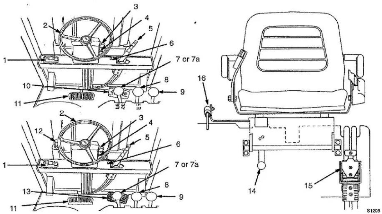
FIGURE 4. INSTRUMENTS AND CONTROLS
MODEL DESCRIPTION
Yale
INSTRUMENTS AND CONTROLS
(See FIGURE 4. through FIGURE 6. and TABLE 1. through TABLE 4.)

WARNING
If any of the instruments, levers, or pedals do not operate as described in the following tables, report the problem immediately. Remove key and put a tag on the truck. DO NOT operate the lift truck until the problem is corrected.
TABLE 1. INSTRUMENTS AND CONTROLS (See FIGURE 4.)
| ITEM NO. | ITEM | FUNCTION |
| 1 | Standard Display Panel | See DISPLAY PANEL FEATURES of this section, FIGURE 5. and TABLE 2. for information on the Standard Display Panel. |
| 1 | Premium Display Panel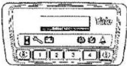 | See DISPLAY PANEL FEATURES of this section, FIGURE 6. and TABLE 3. for information on the Premium Display Panel. |
| 2 | Steering Wheel | The steering wheel controls the movement of the steer wheels. Rotate the steering wheel clockwise for a right turn and counter-clockwise for a left turn. |
| 3 | KeySwitch  | The key switch has two positions:1.OFF deenergizes all electric circuits except for the horn.2.ON energizes all electric circuits and permits the controller to energize the power circuits selected by the operator. Turn the key switch OFF whenever leaving the lift truck. |
| 4 | Lever for Steering Column Adjustment | This lever permits moving the steering column so that the battery can be removed. Permits adjustment of the angle of the steering wheel for operator comfort. |
| 5 | Parking Brake Lever  | The truck is equipped with a hand lever for operating the parking brake. The hand lever is to the right of the steering column. Turn the adjusting knob on the lever to adjust the force applied to the brakes.WARNINGCorrect adjustment is necessary to provide adequate braking and to keep the parking brake lever in the engaged position. See the Maintenance section for the adjustment procedures.Always apply the parking brake when you leave the lift truck. |
MODEL DESCRIPTION
Yale
| ITEM NO. | ITEM | FUNCTION |
| 6 | Light Switch | Controls the lights on lift trucks equipped with lights. |
| 7 | Mast Control Lever (Option if not equipped with separate TILT and LIFT/LOWER control levers) | The mast control lever is the first lever to the right of the seat. Push the lever forward to lower the forks. Pull the lever backward to raise the forks. Push the lever to the right and then push the lever forward to tilt the mast and forks forward. Push the lever to the right and then pull the lever backward to tilt the mast and forks backward. |
| 7a | LIFT/LOWER Control Lever (Option if not equipped with a single mast Control Lever) | The LIFT/LOWER control lever is the first control lever at the right of the seat. Pull backward to raise the forks. Push forward to lower the forks. |
| 8 | TILT Control Lever (Option if there is not a single mast Control Lever) (Not shown in FIGURE 4.) | The TILT control lever is to the right of the LIFT/LOWER control lever. Push the lever forward to tilt the mast and forks forward. Pull the lever backward to tilt the mast and forks backward toward the lift truck. |
| 9 | Attachment Control Lever | If the lift truck is equipped with an attachment, such as a side shift carriage, an additional lever will be mounted to the right of the mast control lever. The attachment control lever can be used to operate one or two additional hydraulic functions. See TABLE 3. |
| 10 | Foot Directional Control Pedal  | When the lift truck is equipped with a Foot Directional Control pedal, the direction and the speed of travel are controlled by the Foot Directional Control pedal. When the right side of the pedal is pushed, the lift truck will move in the REVERSE direction. When the left side of the pedal is pushed, the lift truck will move in the FORWARD direction. The speed of the lift truck increases as the pedal is pushed down. |
| 11 | Brake Pedal  | This pedal, controlled by the operator's foot, applies the service brakes. |
| 12 | Direction Control Lever [ACOS] | The direction control lever is used on some lift trucks. When the lift truck is equipped with a direction control lever, it will also have an accelerator pedal instead of a Foot Directional Control pedal. The direction control lever has three positions: FORWARD, NEUTRAL and REVERSE. Move the lever to one of the direction positions for travel. |
| 13 | Accelerator pedal  | The accelerator pedal is used with the direction control lever described in Item 12. Push down on the accelerator pedal to increase the speed of the lift truck. |
MODEL DESCRIPTION
Yale
| ITEM NO. | ITEM | FUNCTION |
| 14 | Knob for Battery Restraint | A sliding latch mechanism locks the battery restraint (seat plate) in the down position for lift truck operation. A knob near the hinge unlocks the battery restraint from the frame so that the battery restraint and seat can be raised for battery access. Push the knob toward the floor plate to unlock the battery restraint. The steering column must be tilted forward and the seat moved to the rear adjustment position to raise the seat and battery restraint. A spring brace holds the seat and battery restraint in the up position. Push the assembly toward the battery until the latch locks for operation. Handles on the plate can be used to lift and lower the battery restraint.These units have a battery retention bar that has a hinge at the counterweight. This bar is locked under the seat and will be raised with the hood assembly for battery access. Make sure the battery has a cover if the lift truck does not have a hood. |
| 15 | Battery Connector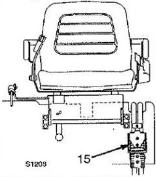 | The battery connector is in two parts. One half of the connector is attached to the battery cables. The other half of the connector is connected to the electrical system of the lift truck.If an SB or SBX connector is used, make sure the over center handle is installed on the connector. The handle is used to connect and disconnect the two halves and also lock the two halves together.CAUTIONMake sure both halves of the connectors are the same type and color.Make sure the voltage of the battery is the same as specified on the nameplate. The halves of the connector must be joined for operation.Separate the halves of the connector to disconnect the battery. |
| 16 | Gas Spring | The gas spring reduces the effort required to lift the seat. |
MODEL DESCRIPTION
Yale
DISPLAY PANEL FEATURES
The following features are part of both the Standard and Premium Display Panels:
• LED (Light Emitting Diode) symbol indicators
• LCD (Liquid Crystal Display) screen
- Battery Discharge Indicator (BDI) (with lift interrupt when enabled)
• Service Reminder (if enabled)
- Status Codes
• Hourmeter of traction and lift pump times
These features are shown in the standard display panel. See FIGURE 5. The symbol indicators are shown and described in TABLE 2. Since they are common features, these features are also shown in the premium display panel. See FIGURE 6. Descriptions of these features follows. The symbol indicators are also shown and described in TABLE 3.
Descriptions Of Common Features
LED SYMBOL INDICATORS
The LED symbol indicators are bright red and indicate the function that is shown on the LCD screen. Some of them are also used as a visual warning for the operator of a potential problem that needs an action from the operator.
LCD SCREEN
The LCD screen shows operator messages for the different functions. The Standard display panel can show a maximum of 16 numbers (including spaces).
BATTERY DISCHARGE INDICATOR (BDI)
The Battery Discharge Indicator (BDI) uses a bar graph as a "fuel" gauge for the battery state-of-charge. As the battery discharges, the bar gets shorter to show less "fuel". The green band near the bar shows the normal operating range for the battery. The yellow band is the area that the battery can still be operated in without damage. This band is yellow to indicate that the battery is nearing the point of discharge where it can be damaged with continued hard use. The red band indicates the discharge condition where battery damage can occur. The battery
indicator symbol will come ON at this time. Charge the battery very soon to prevent battery damage. Continued operation will cause Lift-Interrupt (if enabled) to occur to help prevent battery damage. At lift-interrupt, the last two segments of the bar graph are the only ones shown and are alternately ON and OFF. The lift pump motor will not operate and there will be a reduction of travel speed.
SERVICE REMINDER
The Service Reminder feature (if enabled) lets the operator know when it is time for periodic maintenance. A status code of 99 will show on the LCD screen and the wrench symbol will be ON. If maintenance is not done within 20 more hours of operating time, lift truck operation will be slower until maintenance is done. Have the maintenance done by authorized maintenance personnel. The service personnel must also set the memory for the next maintenance interval to allow normal operation again.
STATUS CODES
Status Codes give an indication to the operator that a possible malfunction or incorrect truck use has occurred. Status Codes are code numbers for a symptom or malfunction. The wrench symbol will flash and the status code number will be shown on the LCD screen if a possible symptom or malfunction occurs during operation. Have authorized service personnel check and repair the lift truck if a status code number appears. The symptoms for each status code are shown in the Service Maintenance Manual.
HOURMETER
The Hourmeter shows the operating time in hours on the LCD screen as a five digit number. The display is shown for four seconds after the lift truck has been operating and the key is moved to the OFF position. Traction time is the time that the key has been in the ON position with the operator in the seat. The operating time for the pump motor (with illuminated symbol) will also be displayed as a five digit number for four seconds following the traction time.
The Premium Display Panel will show the hours as described above. TRACTION HOURS will also be shown on the LCD screen following the traction motor hours. PUMP HOURS will also be shown on the LCD screen when the pump motor hours are shown.
MODEL DESCRIPTION
Yale
Normal Sequence Of Operation - Standard Display Panel
Following is the normal sequence that occurs after the operator is on the seat with the battery connected:
- Red indicator symbols and all 16 segments of LCD screen are on for one second after the key is moved to the ON position. Seat belt symbol will be on for an additional four seconds.
- The bar graph for battery-state-of charge is on LCD screen. If the battery is discharged to Lift-Interrupt, the battery indicator symbol will also be flashing. If a battery of the wrong voltage has been installed, the battery indicator symbol will also be on. If necessary correct these problems before attempting normal operation.
Turn the key to the OFF position. The following display sequence will occur:
- Display shows the hourmeter hours for the traction motor for four seconds.
- Display shows the hourmeter hours for the hydraulic pump motor for four seconds. If there is no motor controller for the hydraulic pump, the display will be blank.
Additional Features Of Premium Display Panel
The following additional features are part of the Premium Display Panel:
- Operator Passwords for restricted use and custom lift truck operation (if enabled)
• Daily Check List And Service Items shown on LCD screen (if enabled)
• Performance Modes of operation - Status Code Lists of possible malfunctions or symptoms that have occurred
- Adjustable battery discharge indicator for condition and capacity of battery
The additional features of the premium display panel are described below and shown in FIGURE 6. Also see TABLE 3.
Descriptions Of Additional Features (Available With The Premium Display)
LCD SCREEN
NOTE: The words shown in all capital letters show the words that are on the LCD Screen in the following descriptions.
The LCD Screen shows the information for the additional features as follows: 1) password request (if enabled), 2) operator Check List (if enabled), 3) status code history and 4) information for adjustment of Battery Discharge Indicator. The Premium display panel can show a maximum of 20 letters or numbers (including spaces) in each of two lines. The additional 24 spaces can be used for short messages. The messages provide the operator with necessary information for these features and correct operation.
OPERATOR PASSWORDS
The Operator Passwords are a series of four numbers. Each of the four number digits can be the numbers 1 through 5. If enabled, the password number series must be entered into the memory by a technician and assigned to an operator. Up to 255 passwords can be entered. The password numbers are not displayed, for security, when entered. Remember the password. A technician can use a , personal computer (PC), connected to the display panel, to check as well as assign the passwords.
NOTE: The computer does not always respond immediately for every pushbutton entry. The push button can also "click" without an actual change occurring. Make sure to watch LCD screen and wait for response before requesting another action.
The LCD screen will show ENTER PASSWORD after the key is moved to the ON position when this function is enabled. Use the numbered pushbuttons to enter your four digit password. A "star" symbol will be shown for each digit. The operator has two tries to enter password correctly. If system does not find the password after the first entry, re-enter PASSWORD INPUT PASSWORD ERROR will appear. If system still does not find the password after this second entry, CALL SUPERVISOR INPUT PASSWORD ERROR will appear.
DAILY CHECK LIST AND SERVICE ITEMS
A list of items for Daily Checks And Service will be shown on the LCD screen (if enabled) after the password is accepted. The Check List has items the operator needs to
MODEL DESCRIPTION
Yale
check as having been done. This Check List MUST be completed before the lift truck will operate. Push the push-button #1 for YES and #4 for NO after each item in Check List. These YES answers indicate that the operator says the check or maintenance has been done. The screen will show SERVICE REQUIRED for a NO answer and the lift truck will only operate in "MODE 1". This operating mode will continue until a service person performs the required service and "clears" the message. Additional Check List items will not appear until after service is complete.
PERFORMANCE MODES
Four different Performance Modes of operation can be selected. Each mode can change acceleration, top speed and lifting speeds. The factory settings increase operating speeds from slowest 1 to fastest 4. After the message MODE #X is on the LCD screen, you can change modes. The mode number that was last activated will appear. If you want to change the mode, push the number pushbutton 1, 2, 3, or 4 to select a new mode. The screen will show REQUESTING MODE #Y (Y is the new mode number just entered). The message will then show MODE #Y unless this mode is not permitted under your password. The lift truck will now operate within the parameters set for that mode number until you change
the operating mode number again. A service person can change the operating parameters of each of the four different levels or modes of operation.
STATUS CODE LISTS
The Status Code Lists are lists of all status codes for the malfunctions or symptoms that have occurred since the list was last cleared of entries by a technician. These status codes are NOT of malfunctions or symptoms that are currently present, but those that have occurred in the past. There are separate lists for the Traction Circuit and the Lift Pump Circuit. The lists can only be read with the key in the OFF position.
To access the status code history, wait until after the traction and pump hours have been displayed, then push the "STAR" pushbutton. The first item in the Menu on the LCD screen is ACTIVATE FAULT CODE DATA KEY 5 NXT 1/4. Now push pushbutton 5 for a display of: REQUESTING TRACT 1 HISTORY. All of the status codes in the list for the traction circuit will now be shown in turn. The screen will then show REQUESTING PUMP HISTORY followed by the status codes in the list for the lift pump circuit. After the last status code, END FAULT CODE HISTORY will be shown.
ADJUSTMENT OF BDI
This adjustment allows adjustment for more accurate indication of Battery-State-Of-Charge and Lift-Interrupt (if enabled). This adjustment can be necessary initially and when using batteries in different conditions in your lift truck. The adjustment can only be made with the key in the OFF position. If you think the bar graph is not correct for the battery in your lift truck, have a technician check the the battery with a hydrometer. The technician can then change the setting as necessary.
Normal Sequence Of Operation - Premium Display Panel
Following is the normal sequence that occurs after the operator is on the seat with the battery connected:
- After the key is moved to the ON position, ENTER PASSWORD will be on the LCD screen if this function is enabled.
-
After password is correctly entered, or if it is disabled, the first item of the Check List will be on the LCD screen if this function is enabled.
-
After Check List is complete, or if it is disabled, the red indicator symbols and all 40 segments of LCD screen are on for one second. Seat belt symbol will be on for an additional four seconds.
- The last Performance Mode operation will be on the LCD screen as MODE #. The bar graph for battery-state-of charge is also on LCD screen. If the battery is discharged to Lift-Interrupt, the battery indicator symbol will also be flashing. If a battery of the wrong voltage has been installed, the battery indicator symbol will also be on. If necessary correct these problems before attempting normal operation.
Turn the key to the OFF position. The following display sequence will occur:
- Display shows the hourmeter hours for the traction motor and the words TRACTION HOURS for four seconds.
- Display shows the hourmeter hours for the hydraulic pump motor and the words PUMP HOURS for an additional four seconds. If there is no motor controller for the hydraulic pump, the display will be blank.
MODEL DESCRIPTION
Yale

FIGURE 5. STANDARD DISPLAY PANEL
TABLE 2. COMMON FEATURES (See FIGURE 5.)
| ITEM NO. | ITEM | FUNCTION |
| 1 - 3 and 5 - 7 | All Indicator Symbols | STANDARD DISPLAY PANELThe red indicator symbols are ON for one second after the key is moved to the ON position. This on time checks that the indicators are operating.PREMIUM DISPLAY PANELThe red indicator symbols are ON for one second after the Check List (if enabled) is complete. If there is no Check List, the indicator is ON after password (if enabled) or after the key is moved to the ON position. This on time checks that the indicators are operating. |
| 1 | HourmeterIndicator Symbol [ADTS] | The hourmeter symbol is ON when the traction or lift pump hours are shown on the LCD screen. |
| 2 | Wrench IndicatorSymbol  | This red indicator is ON when status code numbers are shown or when maintenance is due. (99). |
| 3 | Battery IndicatorSymbol  | This red indicator is ON when the battery needs charging or the wrong voltage battery is connected to the battery connector of the lift truck. |
MODEL DESCRIPTION
Yale
| ITEM NO. | ITEM | FUNCTION |
| 4 | Battery Discharge Indicator (BDI)DISCHARGED TO YELLOW AREA 51140 51140 | The Battery Indicator Symbol is on and the bar graph is shown on the LCD screen. See Common Features for more information.STANDARD DISPLAY PANELThe bar graph is on the LCD screen after the indicator function check.PREMIUM DISPLAY PANELThe bar graph and the message MODE #X are on the LCD screen after the LED Indicator check is complete. |
| 5 | Brake FluidLow Symbol  | If this indicator symbol is illuminated during operation, the fluid level in the brake fluid reservoir is low and the reservoir must be filled. |
| 6 | Parking Brake Symbol | This indicator symbol is illuminated when the parking brake is applied and the seat switch is closed. The indicator will go OFF when the parking brake is released.If the parking brake is not applied and the operator leaves the seat or turns the key to the OFF position, the symbol and a warning tone will be ON for approximately 10 seconds. |
| 7 | Fasten SeatBelt Symbol  | This indicator symbol will stay illuminated for approximately four seconds, after the indicator check, to remind the operator to fasten the seat belt. |
| 8 | LCD "Screen" | The display panel, on the left side of the instrument panel (dash), has an LCD window as an operator's "screen" readout for the SEM motor controllers. The screen is illuminated whenever the key is in the ON position and for the first two minutes after the key is first moved to the OFF position. Information with a maximum of 16 characters can be shown. This information includes the following: (1) traction operating time in hours, (2) lift pump operating time in hours, (3) status code numbers, (4) service reminder code 99 (if enabled) and (5) state-of-charge of the battery.All of the screen segments are shown as solid blocks during the indicator check to show that each segment is operating. |
MODEL DESCRIPTION
Yale

FIGURE 6. PREMIUM DISPLAY PANEL
\$1128
TABLE 3. ADDITIONAL FEATURES (See FIGURE 6.)
| ITEM NO. | ITEM | FUNCTION |
| 1 | Alpha Numerical "Screen" | This LCD screen shows the information for the common features and information for the additional features of the premium display panel, Information with a maximum of 20 characters per line in two lines can be shown. This additional information includes the following (display letters shown in all capital letters): 1) ENTER PASSWORD (if enabled), 2) Check List items (if enabled), 3) status code list (history) with number and short description and 4) Battery Compensation information. The hourmeter times are also identified as TRACTION HOURS or PUMP HOURS.MAINTENANCE REQUIRED is also included with the maintenance reminder code 99 if the function is enabled.All of the screen segments are shown as solid blocks during the indicator check to show that each segment is operating. |
| 2 | "STAR" Push Button | MENU ACCESSThis push button will ONLY make a change when the key is in the OFF position. The star button is used to "open" the Menu from the memory of the display panel. After the Menu is "open", only one Menu item is shown on the LCD screen at one time. |
| 3, 4,5, 6and 7 | Push Buttons #1 through #512345 | These push buttons are used as described in Descriptions Of Additional Features of this manual. |
MODEL DESCRIPTION
TABLE 4. AUXILIARY CONTROL LEVERS
| FUNCTIONThe control levers will be arranged in the following order from left to right. | DIRECTION OF MOVEMENT | |
| LOAD OR EQUIPMENT | CONTROL LEVER | |
| 1 REACH | Retract / Extend | Backward/Forward |
| 2 SIDE SHIFT | Right / Left | Backward/Forward |
| 3 PUSH - PULL | Backward / Forward | Backward/Forward |
| 4 ROTATE | Clockwise / Counterclockwise | Backward/Forward |
| 5 UPENDER | Up / Down | Backward/Forward |
| 6 SCOOP | Up / Down | Backward/Forward |
| 7 LOAD STABILIZER | Down (Clamp) / Up (Release) | Backward/Forward |
| 8 SWING (FORKS) | Right / Left | Backward/Forward |
| 9 SWING (CLAMP) | Right / Left | Backward/Forward |
| 10 L.H. FORK POSITIONER | Together / Apart | Backward/Forward |
| 11 R.H. FORK POSITIONER | Together / Apart | Backward/Forward |
| 12 TURN FORK | Horizontal/Vertical | Backward/Forward |
| 13 FORK SPREAD | Together / Apart | Backward/Forward |
| 14 CLAMP | Clamp / Release | Backward/Forward |
 | ||
OPERATING PROCEDURES
GENERAL
Know Your Lift Truck
The fork lift truck is designed to pick up and move materials. The basic lift truck has a lift mechanism and forks on the front to engage the load. The lift mechanism lifts the load so that it can be moved and stacked.
In order to understand how the fork lift truck can pick up a load, you must first know some basic things about the lift truck.
natural_image
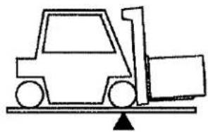
Simple line drawing of a forklift lifting a cargo box on a platform (no text or symbols)The lift truck is based on the principle of two weights balanced on opposite sides of a pivot (fulcrum).
This is the same principle used for a see-saw. In order for this principle to work for a lift truck, the load on the forks must be balanced by the weight of the lift truck. The location of the center of gravity of both the truck and the load is also a factor.
• This basic principle is used for picking up a load. The ability of the lift truck to handle a load is discussed in terms of center of gravity and both forward and side stability.
Stability And Center Of Gravity
The center of gravity (CG) of any object is the single point about which the object is balanced in all directions.
Every object has a CG. When the lift truck picks up a load, the truck and load have a new combined CG.

natural_image
Isometric line drawing of a cube with internal lines and a central shaded region (no text or symbols)
OPERATING PROCEDURES
Yale
The stability of the lift truck is determined by the location of its CG, or if the truck is loaded, the combined CG.
The lift truck has moving parts and therefore has a CG that moves. The CG moves forward and back as the mast is tilted forward and back. The CG moves up and down as the mast moves up and down.

The center of gravity, and therefore the stability, of the loaded lift truck is affected by a number of factors, such as size, weight, shape, and position of the load; the height to which the load is raised; the amount of forward and backward tilt; tire pressure and the dynamic forces
created when the truck is moving. These dynamic forces are caused by things like acceleration, braking, turning, and operating on uneven surfaces or on an incline. These factors must be considered when travelling with an unloaded truck, as well, because an unloaded truck will tip over to the side easier than a loaded truck with its load in the lowered position.
In order for the lift truck to be stable (not tip over forward or to the side) the CG must stay within the area of the lift truck represented by a triangle drawn between the drive axle and the pivot of the steering axle.
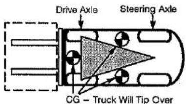
If the CG moves forward of the drive axle, the lift truck will tip forward. If the CG moves outside of the line represented by the lines drawn between the drive wheels and the steering axle pivot, the lift truck will tip to that side.
Capacity (Weight And Load Center)
The weight is specified in kilograms and pounds. The load center is specified in millimeters and inches. The capacity is the maximum load that the lift truck can handle for the load condition shown on the Nameplate.

The load center of a load is determined by the location of its center of gravity. The load center is measured from the front face of the forks, or the load face of an attachment, to the center of gravity of the load. Both the vertical and horizontal load centers are specified on the Nameplate.
Loads should be transported while centered on the centerline of the lift truck. The operator must know whether or not a load is within the maximum capacity of the lift truck before the load is handled.
INSPECTION BEFORE OPERATION

Checks With The Key Switch OFF
Inspect the lift truck before use and every eight hours or daily as described in the MAINTENANCE section of this Operating Instructions manual.
Before using the lift truck, make the following checks:
• Oil level in the hydraulic tank.
• Electrolyte level and specific gravity of the battery are correct.
- Battery weight is within the range of battery weights on the capacity plate.
- Battery restraint mechanism operates correctly and is latched. On lift trucks that have a battery retention bar, the bar must be under the latched seat plate. The bar will be part of the hood assembly on lift trucks with hoods.
- Correct spacers are installed to limit horizontal battery movement.
OPERATING PROCEDURES
Yale
• Condition of forks, carriage, chains, mast and overhead guard.
• Leaks from the hydraulic system.
• Condition of wheels and tires and the air pressure of pneumatic tires.
- Seat belt fastens correctly.
- Seat is securely fastened to the seat plate.
WARNING
Report damage or faulty operation immediately. Do not operate a damaged or defective lift truck. A lift truck will only do its job when it is in proper working order. If repairs are required, install a tag in the operator's area stating "DO NOT OPERATE" and remove the key from the key switch.

WARNING
On ERC70-120HG units, the battery retention bar must be under the latched seat plate. If the bar is not latched, serious injury or death can occur. When the bar is not latched under the seat plate:
• Bar can fall on the operator and cause injury
• Battery can come loose and cause inju- ry or damage
First lower the bar over the battery, then lower the seat and restraint plate over the bar. Make sure the seat plate is properly latched. Make sure the battery has a cover if a hood is not installed.
The PMT Circuit
There is a circuit in the traction control system that monitors components and circuits to make sure they are functioning correctly. This circuit is called the "Pulse Monitor Trip" (PMT) circuit.
The PMT circuit can be checked for correct operation, but a temporary fault must be installed and the wheels raised. See PERIODIC MAINTENANCE 8000 YRM 915 to check the PMT circuit.
The lift truck must not be operated if the PMT circuit does not function correctly.
How To Check The SRO Circuit
The lift truck is equipped with a "Static Return to OFF" (SRO) circuit that prevents travel of the lift truck if the starting sequence is not correct. The function of the SRO circuit is to make sure the operator is in the correct position to operate the controls before the lift truck will operate. The starting sequence:
- Sit on the seat to close seat switch and turn the key to the ON position.
- Select the direction of travel and push the accelerator or push the Foot Directional Control pedal.
If step 2 is done before step 1 and the lift truck moves, the SRO function is not operating correctly. The sequence within step 1 is not important. The lift truck must not be operated if the SRO circuit does not function correctly. If the SRO circuit does not operate correctly, have the Motor Controller checked by authorized service personnel.
When you want the lift truck to travel in the Forward or Reverse direction:
• Make sure a charged battery of the correct voltage is installed and connected
- Sit on the seat to close seat switch and turn key to the ON position.
• Release the parking brake
- Select the direction of travel using the Foot Directional Control pedal or the optional direction control lever
- Push the Foot Directional Control or accelerator pedal for acceleration.
OPERATING PROCEDURES
Yale

Checks With The Key Switch ON
Do not start nor operate the lift truck, including any of its functions or attachments, from any place other than the designated operator's position.

natural_image
Illustration of two workers in hard hats near a large circular structure (no text or symbols)
WARNING
FASTEN\_SEAT BELT If Lift Truck Tips Over
- Do Not Jump - Stay On Truck
- Hold Firmly To Steering Wheel - Brace Feet - Lean Forward And Away From Impact
The seat belt is installed to help the operator stay on the truck if the lift truck tips over. IT CAN ONLY HELP IF IT IS FASTENED.
The operator must be aware that the lift truck can tip over. There is a great risk that the operator or someone else can be killed or injured if trapped or hit by the truck as it tips over. The risk of injury can be reduced if the operator stays on the truck. If the truck tips over DO NOT JUMP OFF.
THE SEAT BELT AND HIP RESTRAINT BRACKET provides a means to help the operator keep the head and torso substantially within the confines of the truck frame and overhead guard if a tipover occurs. This protection system is intended to reduce the risk of the head and torso being trapped between the truck and the ground, but it can not protect the operator against all possible injury in a tipover.
Make sure that the area around the lift truck is clear before making any operational checks. Be careful when making the checks. If the lift truck is stationary during a check, apply the parking brake and make sure the direction control is in NEUTRAL. Proceed carefully.
Check the operation of the following functions as described in the MAINTENANCE section:
- Check the operation of the horn, gauges and indicator lights.
- Operate the LIFT, TILT, and auxiliary functions to check for correct operation of the mast, carriage and attachments.
- Check the operation of the steering system.
- Check the operation of the Foot Directional Control pedal or the optional direction control lever and accelerator pedal.
- Check the operation of the service brakes and parking brake.
• Condition of the forks, carriage, chains, mast and overhead guard.
• Condition of wheels and tires. - Seat belt fastens correctly.
• Hood is securely latched.
OPERATING TECHNIQUES

WARNING
Before operating the lift truck FASTEN YOUR SEAT BELT.

There are a number of operations, if not performed carefully, that can cause the lift truck to tip. If you
have not read the WARNING page in the front of this Operating Instructions manual, do so NOW. As you study the following information about how to properly operate a lift truck, remember the WARNINGS.
Basic Operating Procedures
Many people make the mistake of thinking that operating a lift truck is the same as driving an automobile. This is not true. It is true that some lift truck operating procedures are as simple and obvious as driving the family automobile. (e.g. Look where you are going, start and stop smoothly, etc.) But a lift truck is a special machine designed to do a much different job than an automobile. Because of the close areas in which a lift truck operates and its other operating characteristics (like rear wheel steering and tail swing), every operator must receive additional training, even if they have a license to drive an automobile.
The following discussion lists basic procedures applicable to lift truck operation.

natural_image
Illustration of a forklift operator assisting a worker in a lift (no text or symbols present)OPERATING PROCEDURES
Yale
AUTHORIZED AND TRAINED OPERATOR ONLY. This means the operator must be trained to drive the lift truck and it means that the operator must thoroughly understand the procedures for lift truck operation. It also means that a qualified person experienced in lift truck operation must guide the operator through several driving and load handling operations before the operator attempts to operate the lift truck alone. A basic education in proper driving and load handling techniques is absolutely necessary to prepare the new operator for proper defensive driving and to expect the unexpected.
Operate the lift truck only in areas that have been approved for lift truck operation. Certain areas contain hazardous flammable gases, liquid, dust, fibers or other materials. Lift trucks that are operated in these areas must have special fire safety approval.

These areas must be designated to show the type of lift truck approval required for operation in the area. Changes to special equipment or poor maintenance can make the lift truck lose its special approval.
NO RIDERS. A lift truck is built for only one person -- the operator. It is dangerous for anyone to ride on the forks or anywhere else on the lift truck.
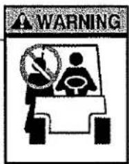

WARNING
This lift truck is designed for handling materials. A lift truck is not designed to lift people. Do not use a lift truck to lift people unless it has been determined that there is no other practical option (scaffolds, elevated work platforms, aerial baskets, etc.) to perform the needed work.

If a lift truck is used to elevate a worker, a safety platform must be attached to the forks and carriage. The platform must be specially built to meet or exceed the requirements of ANSI B56.1. It must have a solid floor with a surface to prevent the feet of the worker from
slipping, hand rail, toe board and a screen or shield at least 7 feet high between the people on the platform and the lift mechanism. Before anyone is allowed in the platform, lift and lower the mast slowly with the platform in place to make sure the mast functions properly. Apply the parking brake. Do not travel with people in the platform. The operator must remain at the controls. Watch for overhead obstructions.
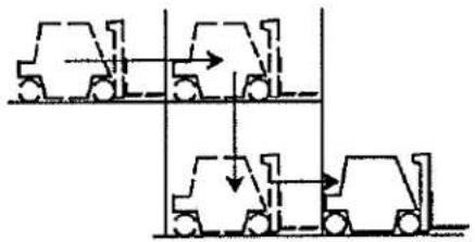
Do not drive a lift truck into a elevator unless authorized to do so. Approach the elevator slowly. After the elevator is properly levelled, the lift truck must be centered so that the elevator is balanced.
flowchart
graph TD
    A["Top: Vehicle with forward load"] --> B["Left: Afterload"]
    B --> C["Right: Backload"]
    C --> D["Bottom: Final load"]
When the lift truck is in the proper position in the elevator, set the brakes, put the controls in NEUTRAL, and shut off the power. It is advisable that all other personnel leave the elevator before the lift truck enters or leaves.
Drive carefully, observe traffic rules and be in full control of the lift truck at all times. Be completely familiar with all the driving and load handling techniques described in this Operating Instructions manual.

Driving And Direction Changes
These lift trucks can have either a Foot Directional Control pedal or a direction control lever. If the lift truck has a Foot Directional Control pedal, push on the left side of the pedal to go FORWARD, or the right side of the pedal to go in REVERSE. If the lift truck has a direction control lever, move the lever toward the front of the lift truck to go FORWARD and toward the rear of the lift truck to go in REVERSE.

FOOT DIRECTIONAL CONTROL PEDAL

ACCELERATOR
PEDAL

OPERATING PROCEDURES
Yale

WARNING
DO NOT select the travel direction if the accelerator or Foot Directional Control pedal is depressed. The lift truck will move rapidly and can cause damage or injury.
To move the lift truck, select a direction, release the parking brake, and push down on the Foot Directional Control pedal or the accelerator pedal.
The operator can change the direction of travel while the lift truck is moving by moving the foot to the other side of the Foot Directional Control pedal, or by moving the direction control lever for travel in the opposite direction. This action uses the motor for braking and can take place at any travel speed.

CAUTION
Do not change direction to travel in reverse when the lift truck is traveling fast. The traction components can be damaged and the load can come off the forks.
The lift truck will come to a stop and then accelerate in the opposite direction, unless the Foot Directional Control pedal or accelerator pedal is released or the direction control lever is moved to the NEUTRAL position. The braking action of the motor can be used to stop the lift truck. To stop the lift truck quickly, use the service brakes.
Steering (Turning)

WARNING
TRAVEL SLOWLY WHEN TURNING. Lift trucks can tip over even at very slow speeds. The combination of speed and the sharpness of a turn can cause a tipover. A lift truck is less stable when the forks are elevated, with or without a load.

natural_image
Cartoon illustration of a person driving on a road (no text or symbols)IF THE LIFT TRUCK TIPS OVER, DO NOT JUMP OFF! HOLD FIRMLY TO STEERING WHEEL, BRACE YOUR FEET, AND LEAN FORWARD AND AWAY FROM THE POINT OF IMPACT.
Most operators can understand the need to be careful when handling loads. But some operators do not realize that a tipover can occur with an empty lift truck because similar dynamic forces are present: In fact, the lift truck will actually tip over easier when empty, than when loaded with the load lowered. Rearward tilt, off-center loads and uneven ground will aggravate these conditions.
Because lift trucks are designed to work in a relatively small space, they can turn sharper than some other vehicles. Most lift trucks are steered by the rear wheels and the rear of the lift truck can move to the side very fast during a turn. This movement is called "tail swing". An operator must be aware of tail swing and always check to make sure the tail swing area is clear before turning.
WARNING
Failure to observe the tall swing area when making a turn can injure or kill someone.

NOTE: On units that have "On Demand" steering, the steering pump motor will stop after a few seconds if the steering wheel is not turned. The pump motor will start immediately if the steering wheel is turned when the key switch is in the ON position.
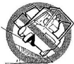
Do not turn on an incline. To reduce the possibility of a tipover, a lift truck must not be driven across an incline.
natural_image
Simple line drawing of a circular object with internal geometric shapes and a diagonal line (no text or symbols)When possible, keep both hands on the steering wheel. During most loading or unloading operations, the operator steers with the left hand. The right hand is used to operate the lift, tilt, and attachment controls.
When turning the lift truck from a wide aisle into a narrow aisle, start the turn as close to the opposite stock pile as tail swing will permit. This action permits the lift truck to enter the narrow aisle going straight ahead.

natural_image
Diagram showing a vehicle with a curved arrow and geometric shapes, no text or symbols presentOPERATING PROCEDURES
Yale
Load Handling, General
The capacity is the maximum load that the lift truck can handle for the load condition shown on the Nameplate. The operator must know whether or not a load is within the maximum capacity of the lift truck before the load is handled.
However, such factors as weak floors, uneven terrain, special load handling attachments or loads having a high center of gravity can mean that the safe working load is less than the rated capacity. When such conditions exist, the operator must reduce the load so that the lift truck will remain stable.
Handle only stable loads. A load can have unstable items that can easily shift and fall on someone.

natural_image
Cartoon illustration of an elephant driving a vehicle with a driver, no text or symbols presentWARNING
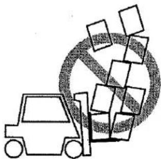
Do not handle a load if any loose part of it is above the load backrest or any part of the load is likely to fall.
natural_image
Illustration of a forklift lifting boxes with a no-smoking symbol (no text or labels)Position each fork the same distance from the center of the carriage. This action will help center the load on the carriage. Set the forks as far apart as possible for maximum support of the load. Center the weight of the load between the forks.
If the weight of the load is not centered between the forks, the load can fall from the forks when you turn a corner or hit a bump. An off-center load will increase the possibility of the truck tipping over to the side.

Make sure the pins that keep the forks in position are engaged so that the forks cannot move.
Check the condition of the driving surface. Make sure the floor will support the weight of the lift truck and the load.
Load Handling, Lifting, Lowering And Tilting
The LIFT and TILT functions are controlled by separate levers. See Instruments And Controls section for the correct operation.
See the Instruments and Controls section for the correct operation. The speed of the hydraulic functions is controlled by the position of the control levers.

The farther the hand lever is moved from the NEUTRAL position, the faster the speed of the hydraulic function.
Do not lift or hit anything that can fall on the operator or a bystander. Remember, a lift truck equipped with a YALE overhead guard and load backrest extension provides reasonable protection to the operator from falling objects, but can not protect against every possible impact.
A lift truck without an overhead guard provides no such protection and other personnel have no overhead protection. Avoid hitting objects such as stacked material that could become dislodged and fall.
OPERATING PROCEDURES
Yale

natural_image
Illustration of a forklift lifting boxes into a warehouse (no text or symbols)The operator must exercise care while working near such objects. Whether the lift truck is loaded or empty, do not travel with the load or carriage in a raised position.

WARNING
Keep yourself and all others clear of the lift mechanism. Never allow anyone under or on the forks.


WARNING
NEVER put hands, arms, head or legs through the mast or near the carriage or lift chains. This warning applies not only to the operator but also a helper.

natural_image
Illustration of a hand holding a circular object with arrows indicating movement or force (no text or symbols)A helper must not be near the load or lift mechanism while the operator is attempting to handle a load. The lift mechanism has moving parts with close clearances that can cause serious injury.
Lift and lower with the mast vertical or tilted slightly backward from vertical. Tilt elevated loads forward only when directly over the unloading place.

natural_image
Line drawing of a forklift lifting a large circular object with diagonal lines (no text or symbols)If the lift mechanism is raised to pick up or deposit a load, keep the tilt angle in either direction to a minimum. Backward and forward tilt are helpful, but they affect side and forward stability. Do not tilt in either direction more than necessary when handling a load that is raised. The lift truck can tip forward if the mast is tilted forward with a load in the raised position.

WARNING
The lift truck can tip over forward when the load is raised. Forward tipping is even more likely when tilting forward, braking when travelling forward or accelerating in reverse.
IF THE LIFT TRUCK TIPS OVER, DO NOT JUMP OFF! HOLD FIRMLY TO STEERING WHEEL, BRACE YOUR FEET, AND LEAN AWAY FROM POINT OF IMPACT.

natural_image
Simple line drawing of a mechanical setup with a block, pulley, and circular element (no text or symbols)Load Handling, How To Engage And Disengage A Load
Avoid fast starts. Sudden movement can cause the lift truck to tip. People can be hurt or killed and material can be damaged.

natural_image
Simple line drawing of a forklift and scattered geometric shapes (no text or symbols)Approach the load carefully. Make sure that the truck is perpendicular to the load. Raise the forks to the proper height for engaging the load.
Move forward slowly until the forks are in position under the load. The forks must support at least two-thirds (2/3) of the length of the load.
OPERATING PROCEDURES
Yale

natural_image
Line drawing of a forklift carrying a cargo box (no text or symbols)Make sure that the load is centered between the forks. Make sure that the forks do not extend past the load so that loads or equipment that are behind the load being lifted are not damaged. Lift the load a small distance from the floor to make sure the lift truck has the capacity to lift the load.

If the forks are longer than the load, move the forks under the load so that the tips of the forks do not extend beyond the load. Lift the load from the surface. Move backward a few inches, then lower the load onto the surface and inch
forward to engage the load against the carriage. Tilt the mast backward just far enough to lift the load from the surface.

natural_image
Simple line drawing of a forklift lifting a box (no text or symbols)When a load is put on the floor, tilt the mast forward to a vertical position and lower the load. Tilt the mast forward to permit smooth removal of the forks. Carefully move the lift truck backward to remove the forks from under the load.
natural_image
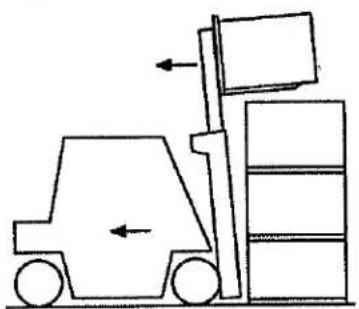
Line drawing of a forklift lifting a pallet stack (no text or symbols)If the load is being removed from a stack, slowly move the lift truck away from the stack. When the load is clear of the stack, lower the load for travelling. Always travel with the load as low as possible and tilted backward. Lowering speed is controlled by the position of the control lever. Lower slowly and smoothly. Slowly return the control lever to the neutral position so that the load is not dropped or that the lift truck is not tipped over due to the rapid stop of the load.
natural_image
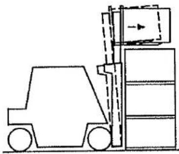
Line drawing of a forklift lifting a stacked pallet (no text or symbols)To put the load on a stack, align the lift truck with the stack. Lift the load to eye level and then tilt the load forward until it is level. Raise the load higher than the point
where it will be placed. Do not raise the load to a point below where the load is to be placed and "jog" the load up into position. This operation uses added energy, particularly with an electric lift truck. Be careful not to damage or move adjacent loads.
WARNING
Move carefully and smoothly when the load is raised over a stack. When the load is elevated the center of gravity of the lift truck and the load is much higher. The lift truck can tip over when the load is raised.
IF THE LIFT TRUCK TIPS OVER EITHER TO THE SIDE OR FORWARD, DO NOT JUMP OFF! HOLD FIRMLY TO STEERING WHEEL, BRACE YOUR FEET, AND LEAN FORWARD AND AWAY FROM THE POINT OF IMPACT.
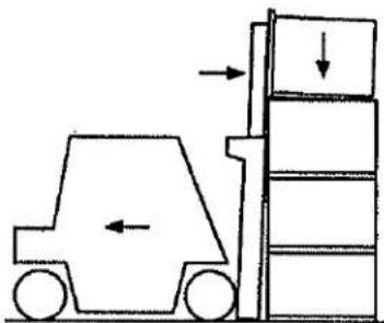
Move forward slowly. When the load is in position, lower the load on to the stack or the rack. Lower the forks just enough to remove them from under the load. Do not lower the forks so that they will drag on the surface under the load. Carefully move the lift truck backward to remove the forks from under the load. Lower the forks when travelling.
OPERATING PROCEDURES
Yale
natural_image
Diagram of a forklift lifting a multi-story vehicle, showing force arrows and load distribution (no text or labels)When lifting round objects, use a block behind the object. Tilt the mast forward so that the forks can slide along the floor under the object to be lifted. Tilt the mast fully backward to help keep the load on the forks.

natural_image
Diagram of a forklift moving with an arrow, next to a sphere rolling down (no text or symbols)
natural_image
Simple line drawing of a forklift lifting a sphere with an arrow indicating rotation (no text or symbols)NOTE: Not every load can be lifted using only the forks of a lift truck. Some loads will require a special attachment.
Load Handling, Travelling
When travelling with the load lowered, keep the load against the carriage and the mast tilted fully backward. This action will help keep the load on the forks and give good forward and side stability.
Travel with the lift mechanism raised only enough to clear the ground or obstacles.

natural_image
Line drawing of a forklift lifting a load (no text or symbols)When the mast, carriage or load is in a raised position the stability of the lift truck is reduced. This stability is also
critical when the lift truck is not carrying a load. The ability of the lift truck to resist side tipping can be less on a lift truck without a load than it is on a lift truck with a load in the lowered (travel) position. Therefore, a lift truck without a load is more likely to tip sideways, especially in a turn, than a lift truck with a load carried in the lowered position.
natural_image
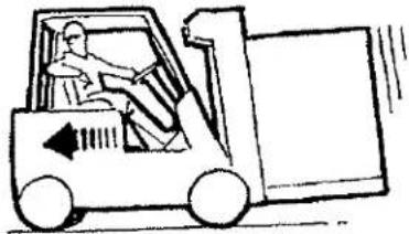
Line drawing of a forklift carrying a truck (no text or symbols)For better visibility with large loads, travel with the load trailing, but always keep a proper look-out in the direction of travel. Normally, direction of travel is determined by the best visibility available to the operator. If the lift truck must travel in a direction where visibility is obstructed, a look-out helper can be required.
WARNING
Some lift trucks have mirrors for viewing along the side to observe the tail swing area. These mirrors are an aid to the driver, but are NOT driving mirrors and must NOT be used as such when operating in reverse. Always look in the direction of travel to avoid damage to something or injury to someone.
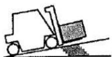
When travelling up or down a grade with a heavily loaded lift truck, keep the load upgrade to maintain control.
When operating an unloaded lift truck on a steep grade, keep the counterweight upgrade.

OPERATING PROCEDURES
Yale
Watch out for pedestrians at all times. Do not drive up to anyone standing in front of an object. Use extra care at cross - aisles, doorways and other locations where pedestrians can step into the path of travel of the lift truck. Slow down when approaching blind intersections or turns and sound the horn. The horn is to warn pedestrians that there is a vehicle in the area and to be alert to possible danger.

Any time the lift truck is moving keep arms, legs, etc., inside the operator's compartment. Arms and legs outside the machine can be injured when passing obstructions.
natural_image
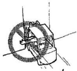
Simple line drawing of a mechanical device with a circular component and shaft (no text or symbols)Avoid bumps, holes, slick spots and loose materials that may cause the lift truck to swerve or tip. If unavoidable, slow down.
natural_image
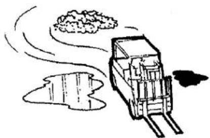
Simple line drawing of a truck with smoke and clouds, no text or symbols presentDifferent models of lift trucks are designed to operate under different conditions. Cushion tire models are designed to operate on relatively smooth, firm surfaces. Always make sure you pick the smoothest route for your lift truck.
Watch clearances, especially forks, mast, overhead guard and tail swing.

natural_image
Diagram of a car under a canopy structure, showing structural components (no text or labels)A lift truck is designed to perform a wide variety of functions within limited space. The operator must be aware
that the forks can sometimes extend beyond the front of the load. If the forks extend beyond the load, the operator can hit an object or lift another load. Serious accidents can be caused by mast and overhead guards hitting pipes and beams near the ceiling.
Do not indulge in stunt driving or horseplay.

natural_image
Illustration of a forklift moving a roller onto a flatbed surface (no text or symbols)Do not pass another lift truck travelling in the same direction at intersections, blind spots or at other dangerous locations.
Stay away from the edge of the road. Keep the wheels of the lift truck, particularly the steer wheels, on the roadway.
If the wheels are allowed to run off the edge of the travel surface onto soft ground, the lift truck can tip over.
Under all travel conditions, operate the lift truck at a speed that will permit it to be brought to a stop in a safe manner.

natural_image
Illustration of a person driving a car with motion lines indicating speed (no text or symbols)HIGHWAY TRUCK, RAILROAD CARS AND DOCKS
WARNING
Maintain a safe distance from the edge of docks, ramps, platforms and other similar working surfaces. Watch the "tall swing". Remember when travelling in the forward direction and the steering wheel is turned to move the lift truck away from the edge of the dock
OPERATING PROCEDURES
Yale
the rear will swing toward the edge. This action can cause the lift truck to fall off the dock.

WARNING
IF THE LIFT TRUCK FALLS OFF THE DOCK, DO NOT JUMP OFF! HOLD FIRMLY TO STEERING WHEEL, BRACE YOUR FEET, AND LEAN FORWARD AND AWAY FROM THE POINT OF IMPACT.

natural_image
Diagram of a mechanical assembly or vehicle with no visible text, numbers, or symbolsBefore operating in a highway truck or railroad car, observe the following:
DO NOT use a lift truck to move a railroad car.
DO NOT use a lift truck to open or close the door on a railroad car unless the lift truck has an attachment that is specifically designed for opening and closing railroad car doors and the operator is trained in its use.
Check to make sure that the brakes on the highway truck are set and that wheel blocks have been placed on both sides of the rear wheels (unless a dock locking mechanism is engaged). Fixed jacks may be necessary to support the front and rear of a highway truck trailer to prevent it from moving or tipping during loading or unloading.

natural_image
Technical line drawing of a mechanical assembly with forklift and three wheels (no text or symbols)Make sure that the railroad car brakes are set and the wheels are blocked while loading or unloading. Do this so that the railroad car will not move due to the movement of the lift truck in and out of the railroad car.
Check the condition of the driving surface. Make sure the floor will support the weight of the lift truck and the load.
Make sure the dock board is secured, in good condition and of the proper capacity.
When entering a railroad car the operator can enter at an angle (if the dock plate or bridge is wide enough). This will reduce the turning required after entering.
ATTACHMENTS
If an attachment is installed on the lift truck, make sure the operating instructions are available and understood before operating the attachment. See TABLE 4. for the operation of attachment control levers.


WARNING
Make sure the capacity plate is correct if an attachment has been installed.
STOPPING
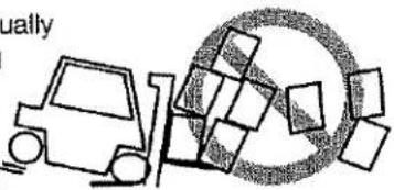
Stop the lift truck as gradually as possible. Hard braking and wheel sliding can cause the load to fall off of the forks and damage the load or hurt someone.
natural_image
Simple line drawing of a forklift moving boxes around a circular object (no text or symbols)PARKING
- The operator must never leave a lift truck in a condition so that it can cause damage and injury. When parking the lift truck, do the following operations:
Stop the lift truck and apply the parking brake.
Fully lower the forks or carriage. Tilt mast forward until the tips of the forks touch the ground.
If equipped, move the direction control lever to the NEU-TRAL position.
Turn the key switch to the OFF position.
Disconnect the battery when leaving the lift truck.
If the lift truck must be left on an incline, put blocks on the down hill side of the wheels so that the lift truck can not move.
Do not park the lift truck so that it limits access to fire aisles, stairways, and fire equipment.
OPERATING PROCEDURES
Yale
NOTES
MAINTENANCE
GENERAL
This section contains a MAINTENANCE SCHEDULE and the instructions for maintenance and inspection.
The MAINTENANCE SCHEDULE has time intervals for inspection, lubrication and maintenance for your lift truck. The service intervals are given in both operating hours recorded on the lift truck hour meter, and in calendar time. Use the interval that occurs first.
The recommendation for the time intervals are for eight hours of operation per day. The time intervals must be decreased from the recommendations in the MAINTENANCE SCHEDULE for the following conditions:
a. If the lift truck is used more than eight hours per day.
b. If the lift truck must work in dirty operating conditions.
Your dealer for Yale lift trucks has the equipment and trained service personnel to do a complete program of inspection, lubrication, and maintenance. A regular program of inspection, lubrication, and maintenance will help your lift truck give more efficient performance and operate for a longer period of time.
Some users have service personnel and equipment to do the inspection, lubrication, and maintenance shown in the MAINTENANCE SCHEDULE. SERVICE MAINTENANCE MANUALS are available from your dealer for Yale lift trucks to help users who do their own maintenance.
WARNING
Do not make repairs or adjustments unless you have both authorization and training. Repairs and adjustments that are not correct can make a dangerous operating condition.
Do not operate a lift truck that needs repairs. Report the need for repairs immediately. If repair is necessary, put a "DO NOT OPERATE" tag in the operator's area. Remove the key from the key switch. Disconnect the battery connector.
Do not work under a raised carriage. Lower the carriage or use a chain to prevent the carriage and the inner or intermediate weldments from lowering when
MAINTENANCE
Yale
doing maintenance. Make sure that the moving parts are attached to parts that cannot move.
CAUTION
Disposal of lubricants and fluids must meet local environmental regulations.
SERIAL NUMBER DATA
The serial number code for the lift truck is on the Name-plate. The code is also stamped on the right side of the rear bulkhead (battery compartment) on the top edge or on the front face near the top.
HOW TO MOVE A DISABLED LIFT TRUCK
WARNING
Use extra care when towing a lift truck if there is a problem with any of the following:
- Brakes do not operate correctly.
- Steering does not operate properly.
- Tires are damaged.
-
Traction conditions are bad.
-
The lift truck must be moved on a steep grade.
If the steering pump motor does not operate, steering control of the lift truck can be slow. This can make the control of the lift truck difficult. If there is no electrical power, there is no power steering. DO NOT tow the lift truck if there is no power. Poor traction can cause the disabled lift truck or towing vehicle to slide. Steep grades will require additional brake force to stop the lift truck.
Never carry a disabled lift truck unless the lift truck MUST be moved and cannot be towed. The lift truck used to carry the disabled lift truck MUST have a rated capacity equal to or greater than the weight of the disabled lift truck. The capacity must be for a load center equal to half the width of the disabled lift truck. See the Nameplate of the disabled lift truck for the approximate total weight. The forks must extend the full width of the disabled lift truck. Center the weight of the disabled lift truck on the forks and be careful not to damage the under side of the lift truck.
How To Tow The Lift Truck
-
The towed lift truck must have an operator.
-
Raise the carriage and forks approximately 30 cm (12 inches) from the surface. Install a chain to prevent the carriage and mast channels from moving.
- If another lift truck is used to tow the disabled lift truck, that lift truck must have an equal or larger capacity than the disabled lift truck. Install an approximate half-capacity load on the forks of the lift truck that is being used to tow the disabled lift truck. This half-capacity load will increase the traction of the lift truck. Keep the load as low as possible.
- Use a solid towing link made of steel that attaches to the tow pins in the counterweights of both lift trucks.
- Release the parking brake.
- Tow the lift truck slowly.
HOW TO PUT A LIFT TRUCK ON BLOCKS
WARNING
The lift truck must be put on blocks for some types of maintenance and repair. The removal of the following assemblies will cause large changes in the center of gravity: mast, drive axle, battery and the counterweight.
When the lift truck is put on blocks, put additional blocks in the following positions:
- Before removing the mast and drive axle, put blocks under the counterweight so that the lift truck can not tip backward.
- Before removing the battery or counterweight, put blocks under the mast assembly so that the lift truck can not tip forward.
Put the lift truck on blocks only if the surface is solid, even, and level. Make sure that any blocks used to support the lift truck are solid, one piece units.
NOTE: Some lift trucks have lifting eyes and these can be used to raise the lift truck so that blocks can be installed.
How To Raise The Drive Tires (See FIGURE 7.)
- Put blocks on each side (front and back) of the steer tires to prevent movement of the lift truck.
- Put the mast in a vertical position. Put a block under each outer mast channel.
- Tilt the mast fully forward until the drive tires are raised from the surface.
- Put additional blocks under the frame behind the drive tires.
MAINTENANCE
Yale
- If the hydraulic system will not operate, use a hydraulic jack under the side of the frame near the front. Make sure that the jack has a capacity equal to at least half the weight of the lift truck. See the Nameplate.
How To Raise The Steering Tires (See FIGURE 7.)
- Apply the parking brake. Put blocks on both sides (front
and back) of the drive tires to prevent movement of the lift truck.
2. Use a hydraulic jack to raise the steering tires. Make sure that the jack has a capacity of at least 2/3 of the total weight of the lift truck as shown on the Nameplate.
3. Put the jack under the steering axle or frame to raise the lift truck. Put blocks under the frame to support the lift truck.

FIGURE 7. PUT A LIFT TRUCK ON BLOCKS
12020
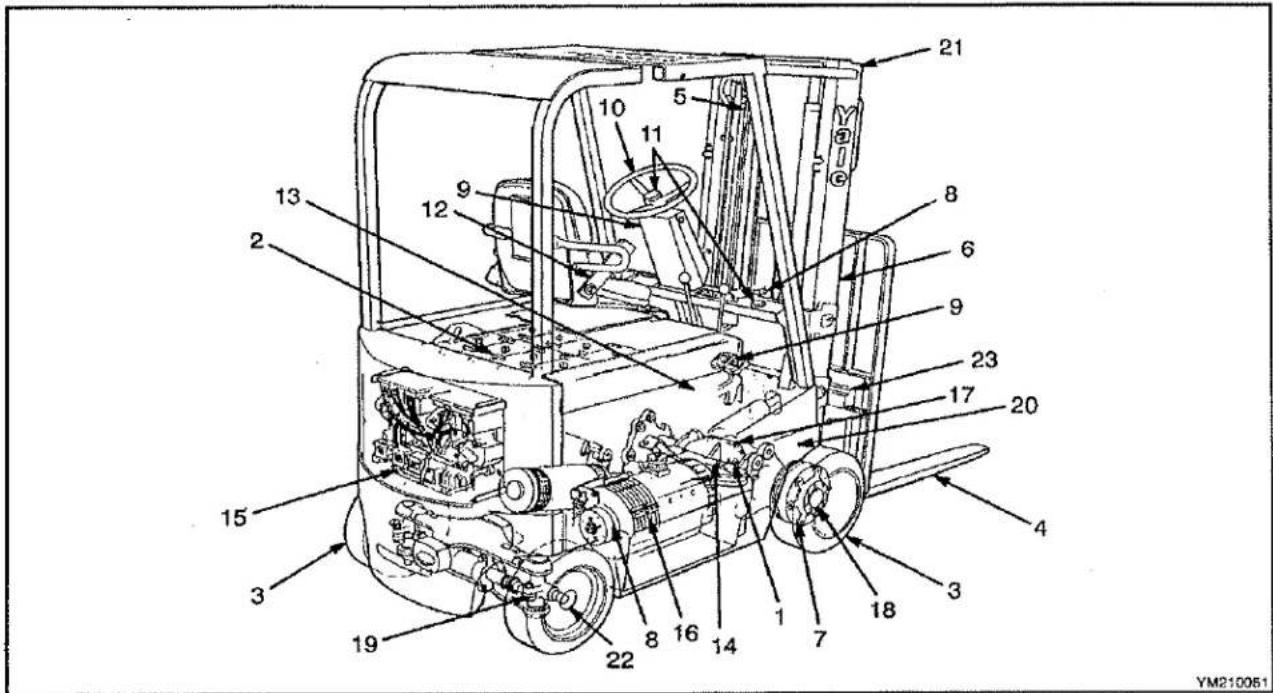
FIGURE 8. MAINTENANCE POINTS
MAINTENANCE
Yale
MAINTENANCE SCHEDULE (ITEM NO. REFERENCE FIGURE 8.)
| ITEM NO. | ITEM | 8 Hr/1 Day | 500 Hr/3 Mos | 1000 Hr/6 Mos | 2000 Hr/1 Year | PROCEDURE OR QUANTITY | SPECIFICATION |
| 1 | HYDRAULIC OIL, Total System ERC070-120HG (SHORT FRAME) | X | C | 41.3 liters (10.9 gal) | -18°C to 38°C(0°F to 100°F)SAE 10W API SC/CC | ||
| 1 | HYDRAULIC OIL (Total System)ERC100 (LONG FRAME) | X | C | 49.2 liters (13.0 gal) | -18°C to 38°C(0°F to 100°F)SAE 10W API SC/CC | ||
| 2 | BATTERYRESTRAINT LATCH | X1X | Check ConditionCheck Operation | ||||
| 3 | TIRES | X | Check Condition | Parts Manual | |||
| 4 | FORKS | X | X | Check Condition | |||
| 5 | LIFT CHAINS | X | L2 | L | Check Condition and Lubrication | Engine oil | |
| 5 | LIFT CHAINS | X | Check Adjustment and Length | ||||
| 6 | MAST SURFACES | L | Check Operation | ||||
| 7 | SERVICE BRAKES | X | X | Check OperationCheck Condition | |||
| X=Check C=Change L=Lubrication NOTE: Never use steam to clean electrical parts. Refer to Service Manual for detailed instruction.1. Equalization Charge is required approximately each month.2. Under dusty or dirty conditions, clean and lubricate more frequently. | |||||||
| SAFETY LABELS | X | Replace if necessary | Parts Manual | ||||
| 8 | PARKING BRAKE | X | L | Check Operation | Yale Part No.504236201 | ||
| 9 | DIRECTION/SPEED CONTROLS | X | C | Check Operation | |||
| 10 | STEERING | X | Check Operation | ||||
| 11 | GAUGES, HORN, LIGHTS,ALARM, FUSES | X | Check Operation | ||||
| 12 | SEAT BELT AND SEAT RAILS | X | Check Condition | ||||
| 23 | FORK GUIDES AND LOCKS | X | L | As Necessary | Engine Oil, API CC/SG SAE20WMIL-L-46152 | ||
| 13 | BRAKE FLUID | X | 0.24 liter (0.5 pt) | SAE J-1703 | |||
| 14 | HYDRAULIC TANK BREATHER | C | Clean or Replace | ||||
| SEAT (PARKING) BRAKEADJUSTMENT | L | Adjust as Required | Yale Part No.504236201 | ||||
| 15 | CONTACTORS | X | C^4 | Check Condition | |||
| 16 | MOTOR BRUSHES | X^3 | Check Condition | ||||
| X=Check C=Change L=Lubrication NOTE: Never use steam to clean electrical parts. Refer to Service Manual for detailed instruction.3. After first 500 hr check, if brush wear allows, extend check interval to 1000 hrs4. Replace hydraulic pump contactor tips every 1000 hours of operation. Replace other contact tips when the tip thickness is 30% of thickness when new. | |||||||
MAINTENANCE
Yale
| ITEM NO. | ITEM | 8 Hr/1 Day | 500 Hr/3 Mos | 1800 Hr/6 Mos | 2000 Hr/1 Year | PROCEDURE OR QUANTITY | SPECIFICATION |
| 17 | DIFFERENTIAL/SPEED REDUCER | X | C | 5.2 liters (5.5) qt) | Ultra Gear Lube Gear OilSAE 80W (Chevron Oil)or SAE 90W EP | ||
| 18 | WHEEL NUTS (Drive Wheel) | X | Check Torque | 680 Nm (500 lbf ft) | |||
| 19 | STEERING SPINDLE AND ROD ENDS | L | 2 FittingsAs Required | Multi-Purpose Grease5 | |||
| 20 | MAST PIVOTS | L | 2 Fittings | Multi-Purpose Grease5 | |||
| 21 | MAST SLIDING SURFACES | L | As Required | Multi-Purpose Grease5 | |||
| HINGES, LEVERS, PEDALS, SEAT RAILS | L | As Required | Yale Part No.504236201 | ||||
| 1 | HYDRAULIC FILTER | C | 1 | See Parts Manual | |||
| 22 | WHEEL BEARINGS | L | As Necessary | Multi-Purpose Grease5 | |||
| X=Check C=Change L=Lubrication NOTE: Never use steam to clean electrical parts. Refer to Service Manual for detailed Instruction.5. Grease with 2-4% Molybdenum Disulfide. | |||||||
MAINTENANCE PROCEDURES EVERY 8 HOURS OR DAILY
WARNING
Do not operate a lift truck that needs repairs. Report the need for repairs immediately. If repair is necessary, put a "DO NOT OPERATE" tag in the operator's area. Remove the key from the key switch.
HOW TO MAKE CHECKS WITH THE KEY SWITCH OFF
Inspect the lift truck every eight hours or daily before use. Put the lift truck on a level surface. Lower the carriage and forks and turn the key to the OFF position. Apply the parking brake. Remove the floor plates and inspect for leaks and conditions that are not normal. Clean any oil spills. Make sure that lint, dust, paper and other materials are removed from the compartments. Make the additional checks as described in the following paragraphs of HOW TO MAKE CHECKS WITH THE KEY SWITCH "OFF" and HOW TO MAKE CHECKS WITH THE KEY SWITCH "ON".
Tires And Wheels (See FIGURE 9.)
Inspect the tires for wire, rocks, glass, pieces of metal, holes, cuts and other damage. Remove any object that will cause damage. Check for loose or missing hardware. Remove any wire strapping or other material that is wrapped around the axle.

11402
- CHECK FOR DAMAGE AND REMOVE NAILS, GLASS, METAL AND OTHER OBJECTS
- MAKE EDGES SMOOTH
FIGURE 9. CHECK THE TIRES
MAINTENANCE
Yale
CAUTION
Check all wheel nuts after 2 to 5 hours of operation: when new lift trucks begin operation and on all lift trucks when the drive wheels have been removed and installed. Tighten the nuts in a cross pattern to the correct torque value shown in the MAINTENANCE SCHEDULE. When the nuts stay tight for eight hours, the interval for checking the torque can be extended to 500 hours.
Make sure the wheel nuts are tight. Tighten the wheel nuts in a cross pattern to the correct torque value shown in the MAINTENANCE SCHEDULE table.
Forks (See FIGURE 10.)
The identification of a fork is determined by how it is connected to the carriage. These lift trucks have hook forks.
ADJUSTMENT
Hook forks are connected to the carriage by hooks and lock pins. See FIGURE 10. These lock pins are installed through the top fork hooks and fit into slots in the top carriage bar. Adjust the forks as far apart as possible for maximum support of the load. Raise the lock pin in each fork to slide the fork on the carriage bar. Make sure the lock pin is engaged in the carriage bar to lock the fork in position after making adjustments.
REMOVAL (See FIGURE 11.)
WARNING
Do not try to lift a fork without a lifting device. The forks can weigh up to 180 kg (400 lb) each.
Slide a hook fork to the fork removal notch on the carriage. Lower the fork onto blocks so that the bottom hook of the fork moves through the fork removal notch. Lower the carriage further so that the top hook of the fork is disengaged from the top carriage bar. Move the carriage away from the fork, or use a lifting device to move the fork away from the carriage.
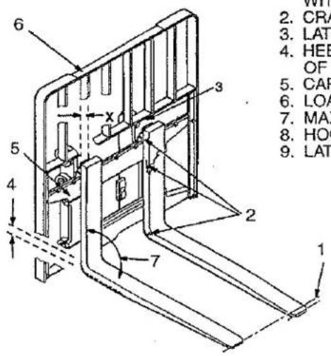
- TIP ALIGNMENT (MUST BE WITHIN 3% OF FORK LENGTH)
- CRACKS
- LATCH DAMAGE
- HEEL OF FORK (MUST BE 90° OF DIMENSION "X")
- CARRIAGE
- LOAD BACKREST EXTENSION
- MAXIMUM ANGLE 93%
- HOOK
- LATCH ASSEMBLY
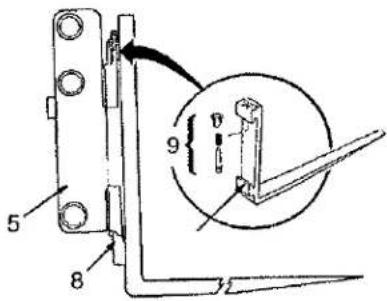
| FORK TIP ALIGNMENT | |
| LENGTH OF FORKS | 3% DIMENSION |
| 915 mm (36 in) | 27 mm (1.10 in) |
| 1220 mm (48 in) | 37 mm (1.45 in) |
| 1830 mm (72 in) | 55 mm (2.15 in) |
BO290000
FIGURE 10. HOOK FORK
MAINTENANCE
Yale
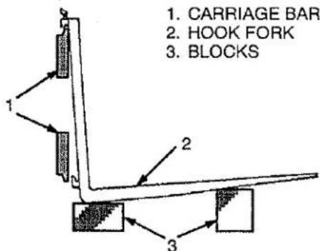
FIGURE 11. REMOVE A HOOK FORK
INSTALLATION
Move the fork and carriage so that the top hook on the fork can engage the top carriage bar. Raise the carriage to move the lower hook through the fork removal notch. Slide the fork on the carriage so that both upper and lower hooks engage the carriage. Engage the lock pin with a notch in the top carriage bar.
. Inspection Of Mast, Forks And Lift Chains (See NO TAG and FIGURE 12.)
WARNING
NEVER work under a raised carriage or forks. Lower the carriage or use chains on the mast weldments and carriage so that they can not move. Make sure the moving parts are attached to a part that does not move.
Do not try to correct fork tip alignment by bending the forks or adding shims. Replace damaged forks.
Never repair damaged forks by heating or welding. Forks are made of special steel using special procedures. Replace damaged forks.
- Inspect the welds on the mast and carriage for cracks. Make sure that the nuts and bolts are tight.
- Inspect the channel for excessive wear in the areas of roller contact. Check the rollers for wear or damage.
- Inspect the load backrest extension for cracks and damage.
-
Inspect the forks for cracks and wear. Check that the fork tips are aligned as shown in item 1 of FIGURE 10. Check that the bottom of the fork is not worn (item 4).
-
Replace any damaged or broken parts that are used to keep the forks locked in position.
- Inspect the lift chains for the correct lubrication. Use engine oil or Chain and Cable Lubricant available from your dealer for Yale lift trucks.
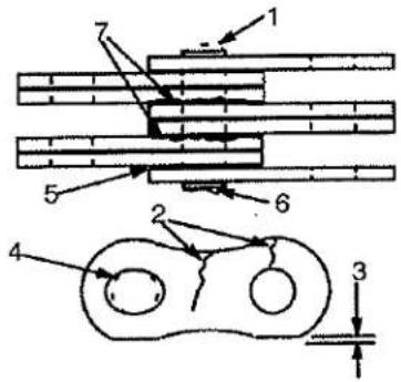
-
WORN PIN
-
LOOSE LEAVES
-
CRACKS
-
DAMAGED PIN
-
EDGE WEAR
-
RUST
-
HOLE WEAR
FIGURE 12. CHECK THE LIFT CHAINS
-
Inspect the lift chains for cracks or broken links and pins. See FIGURE 12.
-
Inspect the chain anchors and pins for cracks and damage.
- Make sure the lift chains are adjusted so that they have equal tension. If the chains need to be replaced or adjusted, it must be done by authorized personnel.
Safety Labels
WARNING
Safety labels are installed on the lift truck to give information about possible hazards. It is important that all safety labels are installed on the lift truck and can be read.
Check that all safety labels are installed in the correct locations on the lift truck. See the PARTS MANUAL or Section 2 of the SERVICE MAINTENANCE MANUAL for the correct locations of the safety labels.
Steering Column Latch
Make sure the latch for the steering column operates correctly. The latch must NOT allow the column to move unless the latch is released.
MAINTENANCE
Yale
Operator Restraint System (See FIGURE 13.)
There is an indicator light on the display panel for the seat belt. The red light is ON as described in the MODEL DESCRIPTION section of this manual. The light can help the operator remember to fasten the seat belt.
The seat belt, hip restraint brackets, seat and mounting, battery restraint (seat plate) and latch are all part of the operator restraint system. Each item must be checked to make sure it is attached securely, functions correctly and is in good condition.
The seat belt must latch securely. Make sure the seat belt extends and retracts smoothly and is not damaged or torn. If the seat belt can not be pulled from the retractor assembly, it must be replaced.
Make sure the seat rails are not loose. The seat rails must lock securely in position, but move freely when unlocked. The seat rails must be securely attached to the mounting surface.

- HIP RESTRAINT BRACKETS
- SEAT BELT
- SEAT RAILS
FIGURE 13. OPERATOR RESTRAINT SYSTEM
Battery Restraint System (See FIGURE 14.)
The battery restraint system is a heavy steel seat plate that has a hinge at the front of the battery compartment. Spacers are used inside the battery compartment to prevent horizontal movement of the battery.
Battery
NOTE: There can be one of two types of batteries. One type has removable cell caps. The other type has sealed cells. The sealed batteries require a different charger, the electrolyte level or specific gravity cannot be checked and water cannot be added to the electrolyte.

WARNING
Never put tools or other metal on the battery. Metal on the battery can cause a short circuit and possible damage or injury.
The acid in the electrolyte can cause injury. If the electrolyte is spilled, use water to flush the area. Make the acid neutral with a solution of sodium bicarbonate (soda). Acid in the eyes must be flushed with water immediately.
Batteries generate explosive fumes. Keep the vents in the caps clean. Keep sparks or open flames away from the battery area. Do not make a spark from the battery connections.
Disconnect the battery when doing maintenance.
Make sure that the voltage and the weight of the battery are correct as shown on the nameplate. See BATTERY SPECIFICATIONS at the rear of this manual to check for correct battery dimensions.
Keep the battery case, top cover and the area for the battery clean and painted. Leakage from the battery and corrosion can cause a malfunction in the electric controls of the lift truck. Use a water and sodium bicarbonate (soda) solution to clean the battery and the battery area. Keep the top of the battery clean, dry and free of corrosion.
Make sure the battery is charged and has the correct voltage and ampere hour rating for the lift truck. See the nameplate.
Inspect the battery case, connector and cables for damage, cracks or breaks. See the battery dealer in the area to repair any damage.
On batteries with cell caps, check the level of the electrolyte daily on a minimum of one cell. Add only distilled water, as necessary, to all cells that do not have the correct electrolyte level. The correct level is half-way between the top of the plates and the bottom of the fill hole.
MAINTENANCE
Yale
Hydraulic System (See FIGURE 15.)

WARNING
At operating temperature the hydraulic oil is HOT. Do not permit the oil to contact the skin and cause a burn.

CAUTION
Do not permit dirt to enter the hydraulic system when the oil level is checked or the filter is changed.
Never operate the pump without oil in the hydraulic system. The operation of the hydraulic pump without oil will damage the pump.
Check the hydraulic oil level when the oil is at operating temperature, the carriage is lowered and the key switch is in the OFF position. Add hydraulic oil only as needed. If more hydraulic oil is added than the FULL level, the hydraulic oil will leak from the breather during operation.
Inspect the hydraulic system for leaks and damaged or loose components.

11450
-
HYDRAULIC TANK
-
BRAKE FLUID RESERVOIR
FIGURE 15. HYDRAULIC AND BRAKE CHECKS
HOW TO MAKE CHECKS WITH THE KEY SWITCH ON

WARNING
FASTEN YOUR SEAT BELT! The seat belt is installed to help the operator stay on the truck if the lift truck tips over. IT CAN ONLY HELP IF IT IS FASTENED.
A battery retention bar is used on all models where batteries can be longer. This bar has a hinge fastened to the counterweight and is part of the hood mechanism on lift truck with hoods. The retention bar is also installed on lift trucks without hoods.
To operate correctly, the battery restraint plate must be locked in the down position. The battery retention bar (and hood) must be lowered first, then the battery restraint plate is locked in the down position over the bar. The battery must have spacers to prevent movement in any one horizontal direction of 13 mm (0.5 in) maximum. Use the knob near the hinge to release the battery restraint plate (see FIGURE 14.) Use the handle on the restraint plate to raise the plate and seat. A spring brace will hold the assembly in the up position. If installed, raise the hood. Make sure that the battery can not move more than a total of 13 mm (0.5 in) in any one horizontal direction. Make sure the correct spacers are installed to prevent the movement. See your dealer for Yale lift trucks to replace damaged or missing spacers. If a smaller battery of the correct weight (see Nameplate) is installed and the spacers cannot prevent movement, your dealer for Yale lift trucks has larger spacers. Push the seat and the battery restraint down until the latch locks. Make sure the battery restraint is locked securely. Lift on the battery restraint to make sure it is latched and will not move.
WARNING
The battery restraint and its latch mechanism must operate correctly before a lift truck is operated. The battery retention bar must be down and under the seat and battery restraint plate. Make sure the battery has a cover if the lift truck does not have a hood.
If necessary, adjust the battery spacer system as described in HOW TO CHANGE THE BATTERY.
MAINTENANCE
Yale
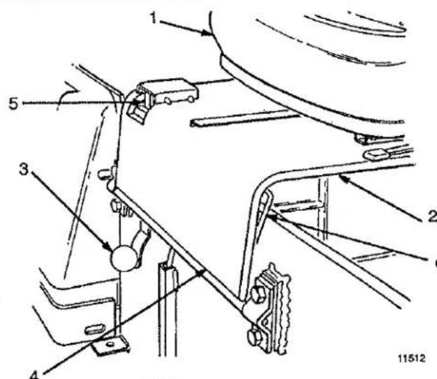
- SEAT
- BATTERY RESTRAINT (SEAT PLATE)
- KNOB FOR LATCH MECHANISM
- HINGE
- LATCH
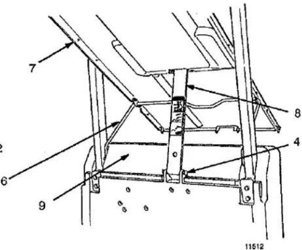
- SPRING BRACE
- HOOD
8 BATTERY RETENTION BAR - COUNTERWEIGHT
FIGURE 14. BATTERY RESTRAINT
Make sure the area around the lift truck is clear before moving the lift truck. Always look in the direction that you intend to move the lift truck. Be careful when making the checks.
Gauges, Horn And Fuse (See TABLE 1.)
- Check the operation of the gauges and horn. The horn will operate when the key is in any position. On both the standard and enhanced panels, the hourmeters record the hours during operation. The hours are displayed on the digital display as described in the MODEL DESCRIPTION section of this manual.
- The battery indicator will operate as described in the MODEL DESCRIPTION section of this manual.
- Most fuses are located in the electrical compartment.
Steering System

WARNING
Because the lift truck has hydraulic power steering, the lift truck can be difficult to steer when the power steering pump is not operating.
Make sure that the steering system operates smoothly and gives good steering control.
Service Brakes (See TABLE 1.)
There is an indicator light on the display panel for the brake fluid level. The red light is ON as described in the MODEL DESCRIPTION section of this manual. If the light is ON during operation, the fluid in the reservoir for the brake master cylinder is too low. Add brake fluid and check for leaks. The reservoir is under the brake pedal and floor plate. Clean the area around the fill cap so that no dirt enters the reservoir.
Check the operation of the service brakes. Push on the brake pedal. The brakes must be applied before the pedal reaches the floor plate. The brake pedal must stop firmly and must not move slowly down after the brakes are applied. The brakes must apply equally to both drive wheels with no noticeable pull to either side. The service brakes are automatically adjusted as the brakes are applied when the lift truck changes directions.
NOTE: Some lift trucks are used in operations where the automatic adjusters can be slow to adjust the brake shoes. If the brakes need adjustment, operate the lift truck in forward and reverse 10 times. Apply the brake
MAINTENANCE
Yale
pedal firmly, but do not cause the wheels to slide. If the automatic adjusters do not adjust the brake shoes, a qualified service person must check the operation and condition of the brakes.

WARNING
Loss of fluid from the brake fluid reservoir indicates a leak. Repair the brake system before using the lift truck. Replace the brake fluid in the system if there is dirt, water or oil in the system.
Parking Brake (See TABLE 1.)
There is an indicator light on the display panel for the parking brake. The red light is ON as described in the MODEL DESCRIPTION section of this manual. If the light is ON after approximately one second, the operator is not on the seat or the key is in the OFF position. An alarm will also make a noise. ALWAYS apply the parking brake when leaving the seat.
Make sure the service brakes operate correctly before checking the operation of the parking brake. Check the
operation of the parking brake. The parking brake, when in good condition and correctly adjusted, will hold a lift truck with a capacity load on a 15% grade (1.5 ft rise in 10 ft). If necessary, adjust the parking brake by first making sure the lift truck cannot move (block wheels). Release the parking brake and remove the floor plates for access to the adjustment knob at the bottom of the pedal linkage. Turn the knob clockwise to increase the braking force.
Some lift trucks are equipped with an additional linkage that automatically actuates a separate brake when the operator leaves the seat (seat brake). When correctly adjusted, this brake will also hold the lift truck with a capacity load on a 15% grade. If the brake does not hold the lift truck on the grade, the seat brake must be adjusted by authorized service personnel according to the procedure in the Brake System 1800 YRM 338.
Control Levers And Pedals
Check that the levers for the mast and attachment operate as described in TABLE 1. and TABLE 4. Check that the brake operates as described in TABLE 1.
Lift System Operation (See TABLE 1. and TABLE 4.)
WARNING
NEVER work under a raised carriage or forks. Lower the carriage or use chains on the mast weldments and carriage so that they can not move. Make sure the moving parts are attached to a part that does not move.
Do not try to locate hydraulic leaks by putting hands on pressurized hydraulic components. Hydraulic oil can be injected into the body by pressure.
- Check for leaks in the hydraulic system. Check the condition of the hydraulic hoses and tubes.
- Slowly raise and lower the mast several times without a load. The mast components must raise and lower smoothly in the correct sequence. The carriage raises first, then the inner mast and intermediate mast (three stage full free lift mast only).
NOTE: Some parts of the mast move at different speeds during raising and lowering.
- The inner mast and the carriage must lower completely.
- Raise the mast one metre (three feet), with a capacity load. The inner mast and carriage must raise smoothly. Lower the mast. All moving components must lower smoothly.
- With the load lowered, tilt the mast backward and forward. The mast must tilt smoothly and both tilt cylinders must stop evenly.
- Check that the controls for the attachment operate the functions of the attachment. See the symbols by each of the controls. Make sure all of the hydraulic lines are connected correctly and do not leak.
HOW TO CHARGE THE BATTERY
WARNING
The acid in the electrolyte can cause injury. If electrolyte is spilled, use water to flush the area. Make the acid neutral with a solution of sodium bicarbonate (soda) and water. Acid in the eyes must be immediately flushed with water.
MAINTENANCE
Yale
Batteries generate explosive fumes when they are being charged. Keep fire, sparks and burning material away from the battery charger area. Prevent sparks from the battery connectors.
Charge batteries only in the special area for charging batteries. When charging the batteries, keep the vent caps clean. The battery charger area must have ventilation so that explosive fumes are removed. Open the hood over the battery or remove the cover if the battery has a cover.
Disconnect the battery when doing cleaning and maintenance.
CAUTION
Never connect the battery charger plug to the plug of the lift truck. You can damage the traction control circuit. Make sure the charger voltage is the correct voltage for the battery.
Use only battery chargers approved by the battery manufacturer or dealer.
Correct use of the hydrometer (FIGURE 16.) and proper operation of the battery charger is important. Follow the instructions of the charger manufacturer. Never let the battery discharge below the minimum value given by the battery manufacturer. A fully charged battery will have a specific gravity of 1.265 to 1.310 at 25°C (77°F). See FIGURE 16. Never charge a battery at a rate that will raise the electrolyte temperature above 49°C (120°F). Do not let a battery stay discharged for a long period of time.
- NORMAL CHARGE: This charge is normally given to a battery that is discharged from normal operation. Many customers charge the battery at regular intervals that depend on use. This procedure will keep the battery correctly charged if the battery is not discharged below the limit. Always use a hydrometer to check the battery if the battery is charged at regular intervals. Frequent charging of a battery that has a 2/3 or more charge can decrease the life of the battery.

natural_image
Illustration of a person using a pipette to test equipment on a tray (no text or symbols visible)| SPECIFIC GRAVITY READING | ELECTRO-LYTE TEMP. | CORRECTION POINTS | CORRECT VALUE |
| 1.210 | 31°C (87°F) | +0.003 | 1.213 |
| 1.210 | 27°C (80°F) | +0.001 | 1.211 |
| 1.210 | 25°C (77°F) | 0.000 | 1.210 |
| 1.210 | 18°C (64°F) | -0.004 | 1.206 |
| +0.001 or -0.001 for each 2°C from the 25°C base value. | |||
FIGURE 16. CHECK SPECIFIC GRAVITY
- EQUALIZING CHARGE: This charge is at a low rate and balances the charge in all of the cells. The equalizing charge is normally given approximately once a month. It is a charge at a slow rate for three to six hours in addition to the regular charging cycle. Do not give an equalizing charge more than once a week. The most accurate specific gravity measurements for a charged battery will be after an equalizing charge. If the specific gravity difference is more than 0.020 between cells of the battery after an equalizing charge, there can be a defective cell. Consult your battery dealer.
NOTE: Many installations have battery chargers that can follow a program to automatically charge a battery according to recommendations of the battery manufacturer. Use the recommendations of the battery manufacturer for charging the battery
HOW TO CHANGE THE BATTERY (See FIGURE 17., FIGURE 18., and FIGURE 19.)
WARNING
Batteries are heavy and can cause an injury. Use care to avoid injury. Do NOT put hands, arms, feet and or legs between the battery and a solid object.
MAINTENANCE
Yale
Make sure the capacity of the crane and spreader bar is greater than the weight of the battery. The weight of the battery is normally shown on the battery case. The maximum battery weight is shown on the lift truck Nameplate. The spreader bar must NOT be made of metal or it must have insulated straps.
The replacement battery must fit the battery area correctly. Use spacers to prevent the battery from moving horizontally in the battery compartment.
Make sure that the battery voltage and weight of the replacement battery is correct as shown on the Nameplate.
Make sure the battery restraint is locked in the down position before the lift truck is operated. Make sure the battery retention bar is lowered and locked under the seat.
Before connecting the battery, make sure the key switch is in the OFF position and the parking brake is set.
- Disconnect the battery. Move the connector and cables so that they will not be damaged when the battery is moved. Tilt the steering column forward and make sure
the detent engages to hold the steering column. Slide the seat to the rear adjustment position. Release the lock on the battery restraint and tilt the battery restraint and seat to the up position. Make sure the battery restraint and the seat are locked in the up position.
- If the lift truck has a hood, open the hood from over the battery. See FIGURE 18. If the battery is not a covered battery, put an insulating cover over the battery. If the lift truck has a battery retention bar, secure the bar in the UP position.
- Use a spreader bar and crane to lift the battery from the lift truck. See FIGURE 19. When a replacement battery is installed, make sure the battery fits the battery compartment. Use spacers to prevent the battery from moving more than a total of 13 mm (0.5 in) in any one horizontal direction. See FIGURE 17.
WARNING
Correct operation of the battery restraint system requires that the battery does not move more than 13 mm (0.5 in). Make sure the battery spacers are correctly adjusted. Use only spacers supplied with the truck.

- BATTERY COMPARTMENT
- BATTERY
- BULKHEAD
-
SPACER
-
SHIM
-
STORE EXTRA SHIMS IN FRONT OF BULKHEAD
-
STORE SPACER UNDER BATTERY COMPARTMENT
FIGURE 17. BATTERY COMPARTMENT SPACERS
- The lift trucks are equipped with adjustable spacers in the battery compartment. See FIGURE 17. Add or remove shims from under the front spacer bar to control the movement of the battery in the forward and backward directions. Install an equal number of shims at each capscrew. Install the unused shims under the nuts of the capscrews (outside battery compartment).
The spacers on each side of the battery can be adjusted to control the movement of the battery from side to side. Access to the nuts for the spacers for the sides of the battery is under the frame near the steer tires. Tighten all capscrews. It can be necessary to install the side spacers facing the opposite direction for some batteries. If the spacers can not be adjusted for a battery that is specified for this lift truck, see your dealer for Yale lift trucks for the correct spacers.
MAINTENANCE
Yale

natural_image
Technical line drawing of a mechanical assembly with no visible text or symbols
natural_image
Technical line drawing of a conveyor belt system with pulleys and a cart (no text or symbols)FIGURE 18. OPEN THE HOOD
11451

natural_image
Line drawing of a person operating a vehicle chassis with visible components and no text or symbolsFIGURE 19. CHANGE THE BATTERY
MAINTENANCE
Yale

- SOLID RUBBER TIRE (PRESS-ON)
- WHEEL
9458
FIGURE 20. WHEEL AND TIRE
TIRES AND WHEELS
(See FIGURE 20. and FIGURE 21.)
WARNING
The type of tires tires are shown on the lift truck Nameplate. Make sure the Nameplate is correct for the type of tires that are installed on the lift truck.
General
These lift trucks use solid rubber tires. Solid rubber tires made from softer or harder material can be installed as optional equipment. The tread on the solid rubber tires
can be either smooth or it can have lugs. Electric compound tires are recommended. Do not mix types of tires or tread on the lift truck. Make sure the type of tires that are installed on the lift truck are the same as shown on the lift truck Nameplate.
Remove The Wheels From The Lift Truck
WARNING
Wheels must be changed and tires repaired by trained personnel only.
Always wear safety glasses.
- Raise the lift truck as described in How To Put A Lift Truck On Blocks in this manual.
- Remove the wheel nuts and remove the wheel from the lift truck. Lift truck wheels are heavy.
Remove The Tire From The Wheel And Install Tire On The Wheel (See FIGURE 21.)
- The correct tools, equipment and a press ring must be used for each size of wheel. Use a press to push the wheel from the rim and tire. The capacity of the press must be approximately 36 000 kg to 181,600 kg (80,000 to 400,000 lb).
NOTE: Make sure the tires are installed on the wheels according to the dimensions shown in FIGURE 21. The tires must be installed the same for both wheels (drive or steer). Also check the Nameplate of the lift truck for the correct tread width.
- When the drive wheels are installed on the lift truck, tighten the wheel nuts to the torque shown in the Specifications column in the MAINTENANCE SCHEDULE.
| WHEEL | TIREWIDTH | OFFSET*MEASUREMENT “A” |
| DRIVE | 229 mm (9 in) | 0 |
| 304 mm (12 in) | 0 | |
| STEER | 152 mm (6 in) | 0 |
| 178 mm (7 in) | 12.7 mm (0.5 in) |
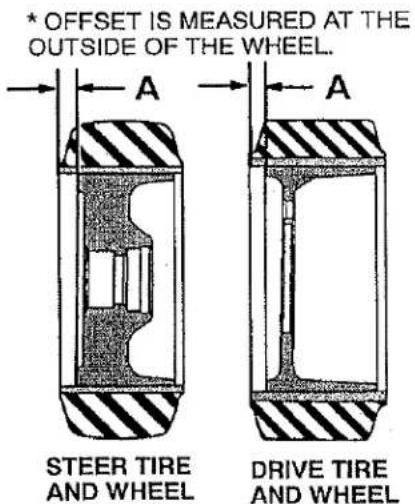
FIGURE 21. WHEEL AND TIRE MOUNTS
12186
MAINTENANCE
Yale
Install The Wheels
- Install the wheel on the hub. Tighten the nuts as shown in the Specifications.

CAUTION
Check all wheel nuts after 2 to 5 hours of operation: when new lift trucks begin operation and on all lift trucks when the drive wheels have been removed and installed. Tighten the nuts in a cross pattern to the correct torque value shown in the MAINTENANCE SCHEDULE. When the nuts stay tight for eight hours, the interval for checking the torque can be extended to 500 hours.
- The steering wheels are fastened to the spindle of the steering axle with a large castle nut. Make sure the inner and outer bearings are correctly lubricated with grease. Install the wheel and inner bearing assembly on the spin-
dle. Install the outer bearing cone and castle nut. Tighten the castle nut to 200 Nm (150 lbf ft) while the wheel is rotated. Loosen the castle nut to less than 27 N.m (20 lbf ft). Tighten the castle nut to 34 Nm (25 lbf ft). Tighten the castle nut to the first position where the cotter pin can be installed. Install the cotter pin.
CHANGES TO THE OVERHEAD GUARD

WARNING
Do not operate the lift truck without the overhead guard correctly fastened to the lift truck.
Do not make changes to the overhead guard by welding. Changes that are made by welding, or by drilling holes that are too big in the wrong location, can reduce the strength of the overhead guard. See the instructions for "Changes To The Overhead Guard" in the SERVICE MAINTENANCE MANUAL.
TABLE 5. BATTERY SPECIFICATIONS*
| MODEL | VOLTS | MINIMUMCOMPARTMENTSIZELength x Width | BATTERYLENGTHMin./Max. | WEIGHT | |
| Minimum | Maximum | ||||
| ERC070HG, ERC080HG | 36 | 841 x 987 mm(33.1 x 38.9 in) | 950 / 990 mm(37.4 / 39.0 in) | 1542 kg(3400 lb) | 2400 kg(5292 lb) |
| ERC100HG-39 | 36 | 841 x 987 mm(33.1 x 38.9 in) | 950 / 990 mm(37.4 / 39.0 in) | 1633 kg(3600 lb) | 2400 kg(5292 lb) |
| , ERC100HG-45 | 36 | 694 x 1037 mm(27.3 x 40.8 in) | 1115 / 1150 mm(43.9 / 45.3 in) | 1814 kg(4000 lb) | 2700 kg(5954 lb) |
| ERC120HG | 36 | 993 x 1146 mm(39.3 x 45.1 in) | 1115 / 1150 mm(43.9 / 45.3 in) | 1919 kg(4231 lb) | 2700 kg(5954 lb) |
| ERC070HG, ERC080HG | 48 | 841 x 987 mm(33.1 x 38.9 in) | 950 / 990 mm(37.4 / 39.0 in) | 1542 kg(3400 lb) | 2400 kg(5292 lb) |
| ERC100HG-39 | 48 | 841 x 987 mm(33.1 x 38.9 in) | 950 / 990 mm(37.4 / 39.0 in) | 1633 kg(3600 lb) | 2400 kg(5292 lb) |
| ERC100HG-45 | 48 | 694 x 1037 mm(27.3 x 40.8 in) | 1115 / 1150 mm(43.9 / 45.3 in) | 1814 kg(4000 lb) | 2700 kg(5954 lb) |
MAINTENANCE
Yale
TABLE 5. BATTERY SPECIFICATIONS*
| MODEL | VOLTS | MINIMUMCOMPARTMENTSIZELength x Width | BATTERYLENGTHMin./Max. | WEIGHT | |
| Minimum | Maximum | ||||
| ERC120HG | 48 | 993 x 1146 mm(39.3 x 45.1 in) | 1115 / 1150 mm(43.9 / 45.3 in) | 1919 kg(4231 lb) | 2700 kg(5954 lb) |
| *BATTERY WIDTHBatteries Without Cover: 950 to 1117 mm (37.4 to 44.0 in)Batteries With Cover: 950 to1143 mm (37.4 to 45.0 in)NOTE: Maximum tolerances are +0 and -13 mm (+0 and -0.5 in) for the size of the battery compartment. The battery specification chart shows the maximum size tolerances that will permit the battery to still fit into a battery compartment. | |||||
NO MATTER HOW YOU SAY IT...
La Prudence Paye
La Seguridad Paga
Betriebssicherheit Macht Sich Bezahlt
Passaa Oll Huoleillinen
Veiligheid Voor Alles
Säkerhet Först
Essere Sicuro Paga
Seguranca Paga
Sikkerhet Først
Pinter Be Awas
सावधान ऋर जिन्दा रहों ।
في التأُني السرّة
安全第一
SAFETY PAYS!
WARNING
California Proposition 65 — This product contains and/or emits chemicals known to the State of California to cause cancer, birth defects, or other reproductive harm.
7/02 (7/00) Printed in U.S.A.

- OPERATING MANUAL
- FOREWORD
- TO OWNERS, USERS, AND OPERATORS:
- Yale
- WARNING
- CAUTION
- CONTENTS
- ⚠ WARNING
- FAILURE to follow these instructions can cause SERIOUS INJURY or DEATH! AUTHORIZED, TRAINED OPERATOR ONLY!
- LOOK WHERE YOU ARE GOING:
- KNOW YOUR LOADS:
- USE COMMON SENSE:
- KNOW THE AREA:
- PROTECT YOURSELF, FASTEN YOUR SEATBELTI
- MODEL DESCRIPTION
- GENERAL (See FIGURE 1.)
- ERC070HG, ERC080HG, ERC100HG-39, ERC100HG-45, ERC120HG
- OPERATOR PROTECTION EQUIPMENT (See FIGURE 1.)
- NAMEPLATE
- SAFETY LABELS
- INSTRUMENTS AND CONTROLS
- DISPLAY PANEL FEATURES
- Descriptions Of Common Features
- LED SYMBOL INDICATORS
- LCD SCREEN
- BATTERY DISCHARGE INDICATOR (BDI)
- SERVICE REMINDER
- STATUS CODES
- HOURMETER
- Normal Sequence Of Operation - Standard Display Panel
- Additional Features Of Premium Display Panel
- Descriptions Of Additional Features (Available With The Premium Display)
- OPERATOR PASSWORDS
- DAILY CHECK LIST AND SERVICE ITEMS
- PERFORMANCE MODES
- STATUS CODE LISTS
- ADJUSTMENT OF BDI
- Normal Sequence Of Operation - Premium Display Panel
- OPERATING PROCEDURES
- GENERAL
- Know Your Lift Truck
- Stability And Center Of Gravity
- Capacity (Weight And Load Center)
- INSPECTION BEFORE OPERATION
- Checks With The Key Switch OFF
- The PMT Circuit
- How To Check The SRO Circuit
- Checks With The Key Switch ON
- FASTEN\_SEAT BELT If Lift Truck Tips Over
- OPERATING TECHNIQUES
- Basic Operating Procedures
- Driving And Direction Changes
- Steering (Turning)
- Load Handling, General
- Load Handling, Lifting, Lowering And Tilting
- Load Handling, Travelling
- HIGHWAY TRUCK, RAILROAD CARS AND DOCKS
- ATTACHMENTS
- STOPPING
- PARKING
- MAINTENANCE
- SERIAL NUMBER DATA
- HOW TO MOVE A DISABLED LIFT TRUCK
- How To Tow The Lift Truck
- HOW TO PUT A LIFT TRUCK ON BLOCKS
- How To Raise The Drive Tires (See FIGURE 7.)
- How To Raise The Steering Tires (See FIGURE 7.)
- MAINTENANCE PROCEDURES EVERY 8 HOURS OR DAILY
- HOW TO MAKE CHECKS WITH THE KEY SWITCH OFF
- Tires And Wheels (See FIGURE 9.)
- Forks (See FIGURE 10.)
- ADJUSTMENT
- INSTALLATION
- Steering Column Latch
- Operator Restraint System (See FIGURE 13.)
- Battery Restraint System (See FIGURE 14.)
- Battery
- HOW TO MAKE CHECKS WITH THE KEY SWITCH ON
- Gauges, Horn And Fuse (See TABLE 1.)
- Steering System
- Service Brakes (See TABLE 1.)
- Parking Brake (See TABLE 1.)
- Control Levers And Pedals
- HOW TO CHARGE THE BATTERY
- HOW TO CHANGE THE BATTERY (See FIGURE 17., FIGURE 18., and FIGURE 19.)
- TIRES AND WHEELS
- Remove The Wheels From The Lift Truck
- Remove The Tire From The Wheel And Install Tire On The Wheel (See FIGURE 21.)
- Install The Wheels
- CHANGES TO THE OVERHEAD GUARD
- NO MATTER HOW YOU SAY IT...
Marque : Yale
Modèle : ERC120HG
Catégorie : Chariot élévateur