
X201D - Magnétophone à cassette AKAI - Notice d'utilisation et mode d'emploi gratuit
Retrouvez gratuitement la notice de l'appareil X201D AKAI au format PDF.


| Type de produit | Magnétophone à cassette stéréo |
| Marque | AKAI |
| Modèle | X201D |
| Dimensions (L x H x P) | 430 x 130 x 280 mm |
| Poids | 5,2 kg |
| Alimentation | Section AC : 220-240V, 50/60Hz |
| Consommation électrique | 30 W |
| Fonctions principales | Lecture, enregistrement, rembobinage, avance rapide, pause, stop, éjection, compteur de bande, arrêt automatique |
| Réduction de bruit | Dolby B et C |
| Têtes | 3 têtes : effacement, enregistrement, lecture |
| Entrées | Ligne (RCA), microphone (Jack 6,35 mm) |
| Sorties | Ligne (RCA), casque (Jack 6,35 mm) |
| Rapport signal/bruit | 62 dB (sans Dolby), 70 dB (avec Dolby C) |
| Pleine bande passante | 30 Hz - 18 kHz (bande normale) |
| Vitesses de bande | 4,76 cm/s |
| Quantité de pistes | 4 pistes (2 stéréo) |
| Entretien et nettoyage | Nettoyer les têtes et le chemin de bande avec un coton-tige imbibé d'alcool isopropylique après 20 heures d'utilisation |
| Sécurité | Éviter l'exposition aux champs magnétiques et à l'humidité. Utiliser sur une surface stable. |
| Pièces détachées et réparabilité | Courroies, têtes, rouleaux disponibles chez les revendeurs spécialisés. Réparation possible par un technicien qualifié. |
| Informations générales | Appareil de la fin des années 1970, fabriqué au Japon. Réputé pour sa fiabilité. |
FOIRE AUX QUESTIONS - X201D AKAI
Questions des utilisateurs sur X201D AKAI
0 question sur cet appareil. Repondez a celles que vous connaissez ou posez la votre.
Poser une nouvelle question sur cet appareil
Téléchargez la notice de votre Magnétophone à cassette au format PDF gratuitement ! Retrouvez votre notice X201D - AKAI et reprennez votre appareil électronique en main. Sur cette page sont publiés tous les documents nécessaires à l'utilisation de votre appareil X201D de la marque AKAI.
MODE D'EMPLOI X201D AKAI
HiFi ENGINE®
For more Hi-Fi manuals and set-up information please visit www.hifiengine.com
X-201D
OPERATOR'S MANUAL
STEREO TAPE DECK

natural_image
Front view of an AKAI X801D audio recording device with two reels and control knobs (no readable text or symbols)CEE, CSA and UL standard models are not equipped with a Voltage Selector or Cycle Conversion Switches. Therefore, voltage and cycle conversion is not necessary. If your machine corresponds to any of these standards, please disregard all references to voltage and cycle adjustment throughout this manual.
CEE Models: 220 V 50 Hz
CSA Models: 120 V 60 Hz
UL Models : 120 V 60 Hz
INDEX
Controls....2
Cross-Field Head Recording System 5
Voltage & Cycle Conversion 6
Tape Loading 6
Tape Speed Selection & Equalizer 7
Fast Forward & Rewind 7
Automatic Stop & Shut-Off 7
Pause Control 7
Monitoring 7
4-Track Recording/Playback System 8
Operating Precautions 8
Playback 9
Automatic Reverse Playback 9
Manual Reverse Playback 9
Recording From Microphones 10
Recording From An External Amplifier 11
Recording From Another Tape Recorder (Tape Dubbing) 11
Recording From A Record Player 11
Din Jack 11
Tape Splicing & Editing 11
Tape Erasing 11
Head Cleaning 12
Head Demagnetizing 12
Technical Data 13
Optional Accessories 14
Standard Accessories 14
CONTROLS
INDEX COUNTER & RESET BUTTON
SUPPLY REEL TABLE
BUILT-IN REEL RETAINER
Locks reel firmly into place.
TAPE SPEED SELECTOR
Set this Selector and the Equalizer Switch to corresponding speed.
CYCLE CONVERSION SWITCH (A)
Out position : 50 Hz., In position : 60 Hz.
Set this switch and Cycle Conversion Switch (B) to correspond with area power source.
TAPE GUIDE
CAPSTAN
TRACK SELECTOR
TAPE TENSION LEVER (SENSING POLE)
PINCH WHEEL
RECORDING SAFETY BUTTON
MANUAL REVERSE BUTTONS
RECORDING LEVEL CONTROL (LEFT)
Adjust while observing left VU Meter.
EQUALIZER SWITCH
MICROPHONE JACKS (LEFT/RIGHT)

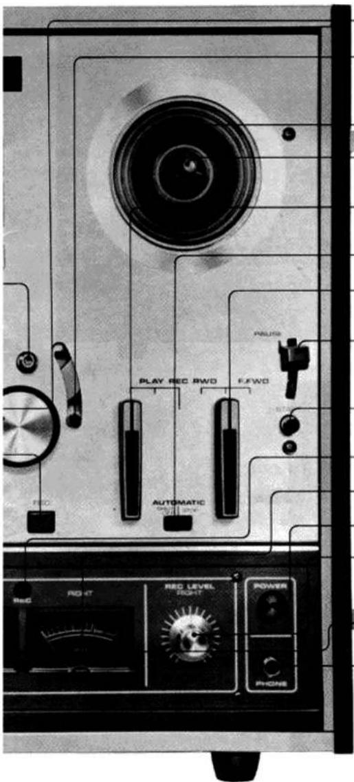
SENSING POLE
AUTOMATIC SHUT-OFF LEVER
Inter-connected with Automatic Stop/Shut-Off Switch for Automatic Stop/Shut-Off.
TAKE-UP REEL TABLE
BUILT-IN REEL RETAINER
Locks reel firmly into place.
PLAYBACK/RECORD LEVER
Advances tape for playback or recording mode.
AUTOMATIC STOP/SHUT-OFF SWITCH
FAST FORWARD/REWIND LEVER
Advances and rewinds tape at fast speed.
PAUSE LEVER
For temporarily suspending tape travel during recording or playback.
START BUTTON
Releases Pause Lever.
RECORDING INDICATOR LAMP
RIGHT VU METER
POWER SWITCH
RECORDING LEVEL CONTROL (RIGHT)
Adjust while observing right VU Meter.
LEFT VU METER
HEADPHONE JACK
Fig. 1
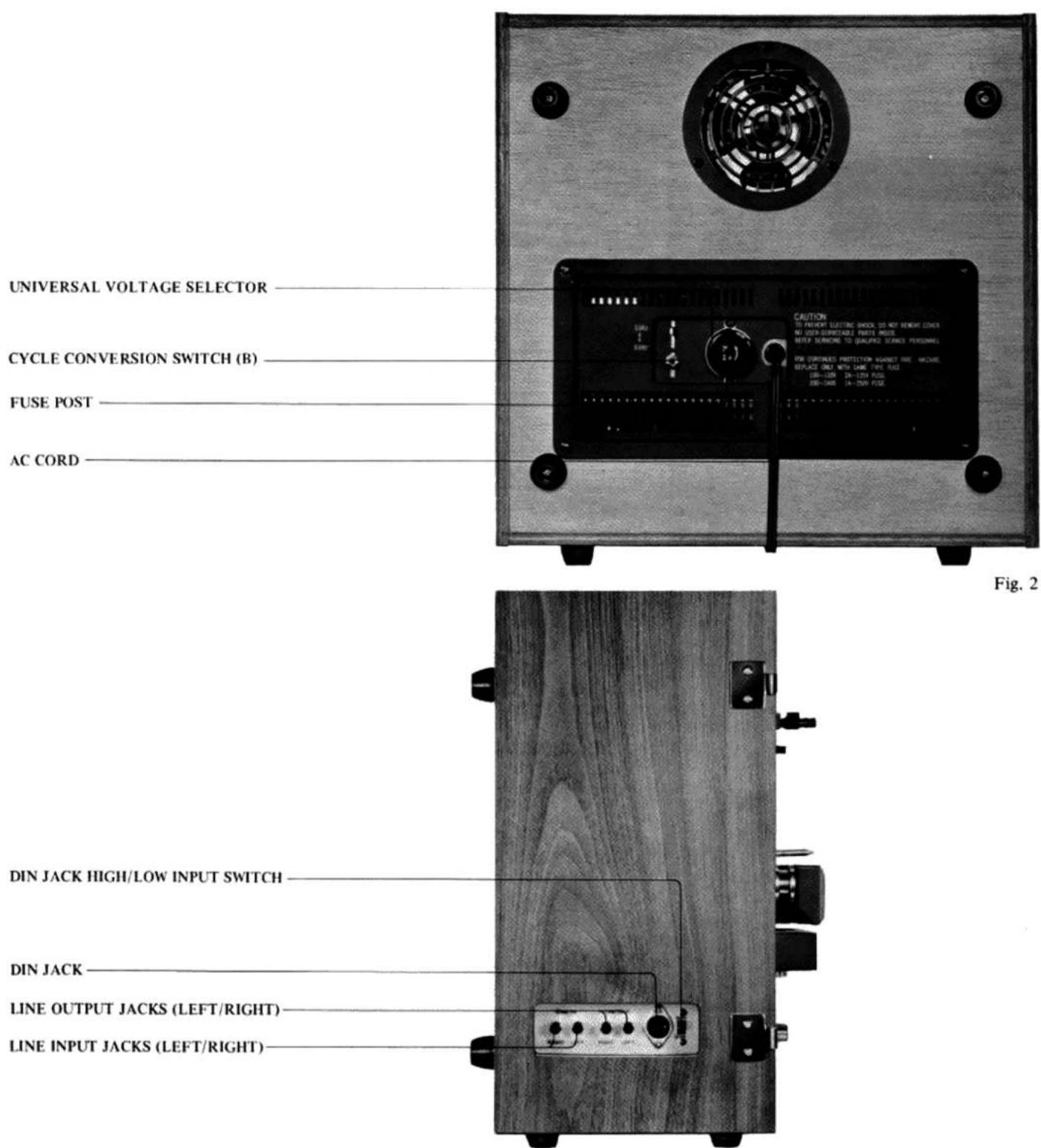
UNIVERSAL VOLTAGE SELECTOR
CYCLE CONVERSION SWITCH (B)
FUSE POST
AC CORD
DIN JACK HIGH/LOW INPUT SWITCH
DIN JACK
LINE OUTPUT JACKS (LEFT/RIGHT)
LINE INPUT JACKS (LEFT/RIGHT)
Fig. 3


Fig. 4
CROSS-FIELD HEAD RECORDING SYSTEM
On conventional recorders, the signal and bias are applied to the same recording head. Therefore, the frequencies recorded, especially high frequency signals, tend to be attenuated or erased by the effect of the bias field.
With the exclusive AKAI CROSS-FIELD HEAD, however, the signal and bias heads are mounted separately in opposition with each other with their centers slightly off. As the recorded signal is entirely unaffected by the prevailing effect of the bias field, tape can be recorded over the entire frequency spectrum with maximum fidelity even at low tape speed.

Fig. 5

Fig. 6

natural_image
Front view of an Akai film reel machine with control panels and drive dials (no visible text or symbols)Fig. 7
VOLTAGE & CYCLE CONVERSION
VOLTAGE
Your machine is equipped with a universal voltage selector offering six selections of voltage from 100 V to 240 V AC for use anywhere in the world. Voltage is preset at the factory according to destination. Please confirm setting prior to operation and if readjustment is necessary, proceed as follows:
- Disconnect power cord and remove the Fuse Post by turning in direction of arrow.
- Remove the Voltage Selector Plug and resinsert so that proper area voltage is shown through the plug cut-out.
- Change fuse to correspond with voltage and tighten the Fuse Post. 100 V to 120 V: 2 A 125 V fuse; 200 V to 240 V: 1 A 250 V fuse.
• To maintain optimum performance and prolong the life of your machine, it is important that the line voltage be held within a 10% deviation of standard area voltage.
CYCLE
Correct tape speed cannot be obtained if the Cycle Conversion Switches are not properly positioned. Cycle Conversion Switch (A) is located on the upper center of the face panel and (B) is located at the rear of the machine. Using a screw driver, rotate Cycle Conversion Switch (A) counter-clockwise approximately one-eighth of a turn. The switch can then be moved to either in or out. The switch must be rotated back to its original position after being reset. Cycle Conversion Switch (B) must be set accordingly. Loosen screw and set to 50 Hz or 60 Hz. Tighten screw.
* Do not attempt to rotate the Cycle Conversion Switches when the motor is not running.
TAPE LOADING
Place a full reel of tape on the Supply Reel Table and an empty reel on the Tape-Up Reel Table. Thread the tape as illustrated by the dotted lines in the figure. Lock reels into place with Reel Retainers provided on reel shafts.

Fig. 8

Fig. 9
natural_image
Illustration of a vintage audio recording device with two reels labeled 'AKAI' connected to a human head silhouette (no text or symbols on the device itself)Fig. 10
TAPE SPEED SELECTION & EQUALIZER
This model operates on three tape speeds: 7-1/2 ips (19 cm/sec), 3-3/4 ips (9.5 cm/sec) and 1-7/8 ips (4.75 cm/sec). Use the Tape Speed Selector for selection of tape speed. A Tape Speed Equalizer is also provided for equalization of the amplifier to correspond with the tape speed. The setting of the equalizer must always correspond with that of the Tape Speed Selector. Recording time using a 1800 ft. tape is: (4-track stereo) 6 hours (1-7/8 ips), 3 hours (3-3/4 ips) and 1.5 hours (7-1/2 ips); (4-track monaural) 12 hours (1-7/8 ips), 6 hours (3-3/4 ips) and 3 hours (7-1/2 ips).
FAST FORWARD & REWIND
For rapid forwarding of the tape set Fast Forward/Rewind Lever to F.FWD position, and for rapid rewinding of the tape set to RWD position. This lever cannot be operated while the Playback/Record Lever is in operation.
AUTOMATIC STOP & SHUT-OFF
The Automatic Stop & Shut-Off functions are also outstanding features of the unit. For automatic stop (to stop reel movement at end of tape), set the Automatic Stop/Shut-Off Switch to STOP position, and for automatic shut-off (to cut off power of the entire unit at end of tape), set to SHUT-OFF position. CEE models are not equipped with an automatic shut-off mechanism.
PAUSE CONTROL
To momentarily stop the tape during recording or playback, set Pause Lever to pause position. Pause control is useful in editing tape during recording, or to adjust input level. To release depress the Start Button.
* Pause control does not function during fast forward or rewind mode.
MONITORING
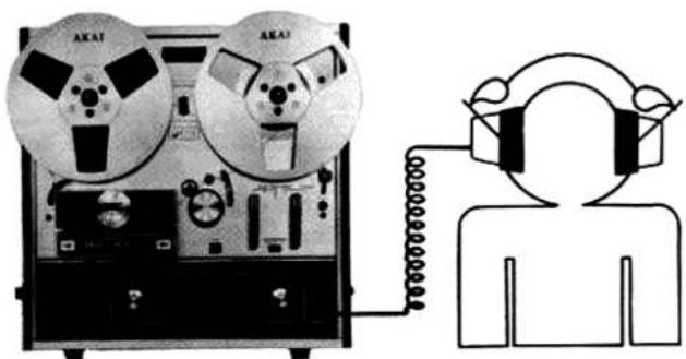
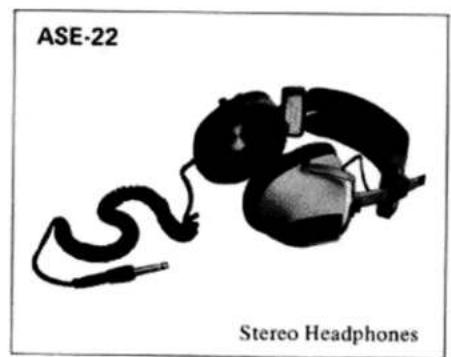
For monitoring, connect stereo headphones to Headphone Jack. Use stereo headphones of low (8 Ω) impedance. Akai model ASE-22 or ASE-20 is highly recommended.
4-TRACK RECORDING/PLAYBACK SYSTEM
This model employs a 4-track system which can be used for either stereo or monaural. Select desired track(s) with the Track Selector.
STEREO RECORDING & PLAYBACK
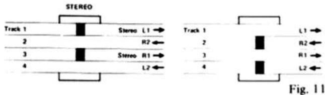
Stereo recording and playback requires the simultaneous use of two tracks. For stereo operation, set Track Selector to STEREO position. The first stereo playback and recording takes place on tracks 1 and 3. The second playback takes place on tracks 2 and 4, after the machine has been set to reverse mode or the reels have been inverted. To record on tracks 2 and 4, invert reels.
MONAURAL RECORDING & PLAYBACK

Fig. 12
Monaural recording and playback track sequence is 1-4-3-2. Set Track Selector to 1-4. The first monaural recording and playback takes place on track 1, and the second on track 4 after the reels have been inverted. Invert reels and set Track Selector to 3-2. The third monaural recording and playback takes place on track 3, and the fourth on track 2 after the reels have been inverted.
This model does not record in reverse direction. For reverse playback, use sensing tape for automatic reverse or the Reverse Button provided on the front panel for manual reverse, or invert reels.
OPERATING PRECAUTIONS
Your machine is constructed of the very finest materials and with proper care will bring you many years of musical enjoyment. We therefore urge you to read the following instructions carefully prior to operation.
• The use of new tapes will result in the best recordings.
* As tape which has not been used for a period of time may have become sticky, run tape one before using.
- Operate machine on a flat horizontal surface in either horizontal or vertical position.
The conditions listed below do not indicate mechanical failure of your unit. If any of these conditions are exhibited, check for trouble as indicated.
Loss of sensitivity and tone quality may be due to :
* Dirty erase head. This prevents pre-recorded materials from being completely erased.
* Dust on recording/playback head. See Head Cleaning procedure.
* Magnetized head. See Head Demagnetizing procedure.
* AC power voltage lower than the voltage to which your machine is set.
Irregularity in tape transport may be due to :
* Improperly loaded tape.
* Grime adhering to the heads.
* Oil on capstan.
• Sticky or dirty tape surface.
* Bent take-up reel.
If your machine will not record, check the following for correct position :
* Input plugs and connections.
* Controls.
The following notes are provided for your convenience.
* Should there be a problem with your machine, please write down model and serial number and all pertinent data regarding warranty coverage, etc., and also as clear a description as possible of the existing trouble and contact your nearest authorized Akai Service Station or the Service Dept. of Akai Company, Tokyo, Japan.
* Your machine requires constant voltage for optimum performance.
* If the sound sources are so far from the microphones that the recording level controls must be turned to maximum, some hum or noise will inevitably be recorded. In such an instance, a test recording is recommended before attempting a final recording.

Fig. 13

flowchart
graph TD
    A["EMER IN"] --> B["AMPLIFIER"]
    C["LINE OUT"] --> B
    D["SPEAKER"] --> B
    E["SPEAKER"] --> B
Fig. 14

Fig. 16
PLAYBACK
For playback of recorded tapes connect the line outputs to the tape inputs of your stereo amplifier and connect a pair of speakers to the amplifier. Connect power cord and load a pre-recorded tape.
STEREO PLAYBACK
(A) Turn on Power Switch.
(B) Set Track Selector to STEREO position.
(C) Set Tape Speed Selector and Equalizer to desired speed.
(D) Set Playback/Record Lever to PLAY position to begin playback.
(E) Adjust external amplifier controls.
MONAURAL PLAYBACK
Only the left channel amplifier is used for monaural playback. Connect the left line output to the left tape input of the external amplifier. Substitute the following for step B of stereo playback procedure and add step F.
Tracks 1 and 4
(B) Set Track Selector to 1-4 TRACK position.
(F) Depress Manual Reverse Button or invert reels for playback of track 4.
Tracks 3 and 2
(B) Set Track Selector to 3-2 TRACK position.
(F) Depress Manual Reverse Button or invert reels for playback of track 2.
* The output level of this model is 1.23 V. Check your amplifier for proper connection.
AUTOMATIC REVERSE PLAYBACK
One of the main features of this model is the automatic reverse playback mechanism which eliminates troublesome inverting of reels by hand. Simple application of a piece of sensing foil to the tape at the desired reversing points is all that is necessary for continuous playback in both directions.
(A) Affix about a 2 cm (3/4") long piece of sensing foil to the outside of the tape at desired reversing point.
(B) If continuous reverse between two points is desired, affix another piece of sensing tape to the inside of the tape at desired reversing point.
As the foil passes the sensing poles, reverse is effected.
MANUAL REVERSE PLAYBACK
This model is also equipped with Manual Reverse Buttons for your convenience. To effect manual reverse, depress Manual Reverse or Normal Play Button.
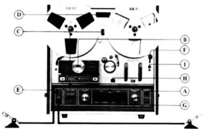
Fig. 17
RECORDING FROM MICROPHONES
STEREO RECORDING
Connect power cord and load a tape. New tape gives best results.
(A) Turn on Power Switch.
(B) Set Track Selector to STEREO position.
(C) Set Tape Speed Selector and Equalizer to desired speed.
(D) With Reset Button, set Index Counter to "0000". This Index Counter provides an easy reference for locating positions on the tape.
(E) Insert microphone plugs into Microphone Jacks. Maintain a distance of at least 2 meters (7 ft.) between microphones.
(F) Set Pause Lever to PAUSE position.
(G) Adjust and balance microphone volume with left and right Recording Level Controls while observing left and right VU Meters. Normal recording should not exceed "0" VU on either of the respective meters.
(H) While holding the Recording Safety Button at depressed position, set Playback/Record Lever to REC position. The Recording Indicator Lamp will light indicating recording mode.
(I) When an optimum recording level has been determined, depress Start Button to release Pause Lever and begin recording.
MONAURAL RECORDING
Only the left channel is used for monaural recording. Substitute the following steps for steps B, E and G of stereo recording procedure and add step K.
Tracks 1 and 4.
(B) Set Track Selector to 1-4 TRACK position.
(E) Insert microphone plug into left Microphone Jack.
(G) Adjust and balance microphone volume level with left Recording Level Control while observing the left VU Meter.
(K) Invert reels to record on Track 4.
Tracks 3 and 2
(B) Set Track Selector to 3-2 TRACK position.
(E) Insert microphone plug into left Microphone Jack.
(G) Adjust and balance microphone volume level with left Recording Level Control while observing the left VU Meter.
(K) Invert reels to record on Track 2.
flowchart
graph TD
    A["Speaker"] --> B["Amplifier"]
    A --> C["Audio Output"]
    D["Speaker"] --> E["Amplifier"]
    D --> F["Audio Output"]
    G["Speaker"] --> H["Amplifier"]
    G --> I["Audio Output"]
    J["Speaker"] --> K["Amplifier"]
    J --> L["Audio Output"]
Fig. 18

Fig. 19
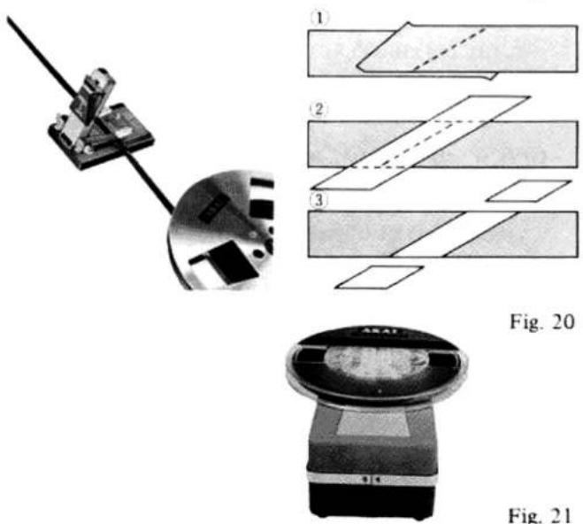
Fig. 21
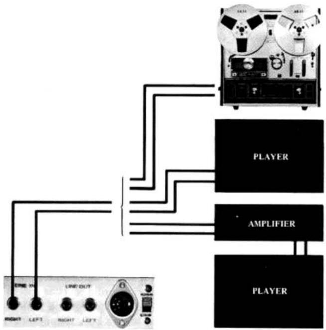
RECORDING FROM AN EXTERNAL AMPLIFIER
If an external amplifier or tuner amplifier is used, connect the recording outputs of the external amplifier to the Line Inputs instead of Step E of recording procedure. This model will record any source which can be selected on the external source.
RECORDING FROM ANOTHER TAPE RECORDER (Tape Dubbing)
Connect the line output jacks of the playback machine to the Line Inputs of this model instead of step E of recording procedure.
RECORDING FROM A RECORD PLAYER
To record from a stereo or monaural disc, a crystal pick-up (0.5 V to 1 V) or a ceramic pick-up can be connected directly to the Line Input Jacks instead of step E of recording procedure. If a magnetic cartridge is used, it must be connected to the Line Input Jacks through an external amplifier.
DIN JACK
The Din Jack at the rear of the unit is for inter-connecting this model with an external stereo amplifier. This system enables easy recording or playback through an external amplifier as the complex connection or disconnection of 4 separate plugs is not necessary. When recording from an external amplifier, if the output level of your amplifier is more than 60 mV, set the High/Low Input Switch to HIGH position, and if the output level is less than 60 mV, set to LOW position.
TAPE SPLICING & EDITING
Cut tape diagonally with an overlap so that the ends are lined up (cutting tape on diagonal eliminates detection of the splice in recording). Cover aligned ends with splicing tape. Press firmly exerting pressure to secure ends evenly. Trim off excess splicing tape, cutting into tape very slightly. This eliminates the possibility of a sticky splice. For smooth and easy splicing, we recommend Akai's portable Tape Splicer AS-3.
TAPE ERASING
Any signal information previously recorded on a tape will be erased automatically as a new recording is made on the same tape. For erasing only, thread the tape and set recorder to normal recording mode. No plugs should be connected to the input jacks. Akai Model ATE-7 Tape Eraser is recommended for complete tape erasure.
natural_image
Illustration of a hand using a stick to measure a small object, no text or symbols presentFig. 22

natural_image
Illustration of a hand holding a tool with a small object nearby (no text or symbols visible)Fig. 23
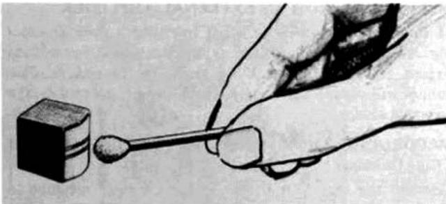
HEAD CLEANING
Accumulation of dust and magnetic particles on the heads results in poor head-to-tape contact and deteriorates sound quality and sensitivity. It is, therefore, recommended that the heads be cleaned every time you use your recorder. Remove the Head Cover and with a stiff cotton swab dipped in cleaning fluid (Akai Head Cleaning Kit HC-500 is highly recommended) rub the entire head surface (do not scratch) until all tape oxide and dust are removed. The capstan shaft, tape lifter and other parts over which the tape travels should also be cleaned.
* Do not use chlorothane as it will damage the rubber wheel.
HEAD DEMAGNETIZING
Normally, the steel pole pieces which form part of the recording and playback head become slightly magnetized. The effect of magnetization will cause considerable drop out or introduce noise into your recordings. It is recommended that head demagnetization be performed periodically. This can be accomplished with a bulk demagnetizer by bringing it close to the heads and making several small circular motions over all head surface areas as well as the head housing.
* Be sure to cut off the power of the unit, prior to demagnetizing the heads.
* Both prongs of the demagnetizer should be covered with masking tape to prevent the heads from being scratched.
* Do not use magnetized tools in the vicinity of the heads.
* Read the demagnetizer's instructions carefully before operation.
STANDARD ACCESSORIES
Connection Cord 1
Sensing Tape 1
Spare Fuse .... 1 set
Operator's Manual 1
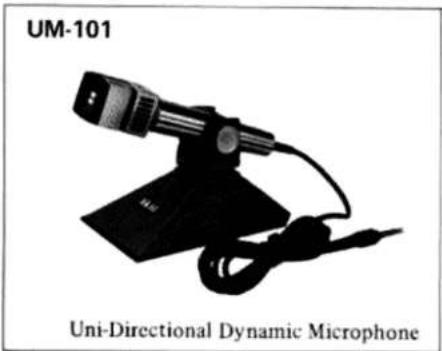
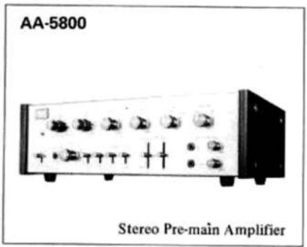
OPTIONAL ACCESSORIES
natural_image
Black-and-white photo of a uni-directional dynamic microphone (no text or symbols on the device itself)
natural_image
A black electronic device labeled 'ATE-7' connected to a cable, with 'Tape Eraser' printed below (no visible text on device body)
natural_image
Close-up of a black electronic device labeled 'AS-3' and 'Tape Splicer', showing no readable text or symbols on the device itself.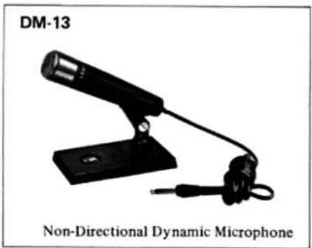
natural_image
Black-and-white photo of a non-directional dynamic microphone with adjustable arm and base (no text or symbols on device)
natural_image
Head Demagnetizer device with coiled cable and strap (no text or symbols visible)
natural_image
Black-and-white photo of a Stereo Headphone device with coiled cable and earpiece (no text or symbols on the device itself)

natural_image
A Stereo Headphones device with coiled cables and a small electronic device (no visible text or symbols on the device itself)
natural_image
Exterior view of a modern speaker system with two speakers and a speaker unit (no text or symbols on the devices themselves)Technische Daten der X-201-D
| Gewicht: | 17 kg |
| Abmessungen: | Breite 358 mm; Höhe 358 mm; Tiefe 227 mm |
| Netzspannung: | Wechselspannung 100–240 Volt |
| Aufnahmesystem: | 4-Spur-Stereo-Kombikopf mit Crossfield-Vormagnetisierungskopf |
| Wiedergabesystem: | 4-Spur-Stereo oder Mono-Wiedergabe mit Kombikopf |
| Bandgeschwindigkeiten: | 4,75 cm, 9,5 cm und 19 cm/sek |
| Max. Abweichungen: | 0,8 % |
| Tonhöhenschwankungen: | Weniger als 0,08 % RMS bei 19 cm/sekWeniger als 0,12 % RMS bei 9,5 cm/sekWeniger als 0,20 % RMS bei 4,75 cm/sek |
| Frequenzbereiche: | 30 Hz bis 26 000 Hz bei 19 cm/sek (± 3 dB)30 Hz bis 18 000 Hz bei 9,5 cm/sek (± 3 dB)40 Hz bis 9000 Hz bei 4,75 cm/sek (± 3 dB) |
| Ruhegeräuschspannungsabstand: | Besser als 50 dB |
| Klirrfaktor: | Innerhalb 3 % gemessen bei 1000 Hz und „0“ dB |
| Übersprechdämpfung: | Weniger als 65 dB (Mono); weniger als 45 dB (Stereo) |
| Löschspannungsabstand: | Weniger als 70 dB |
| Line-Ausgänger: | 1,23 Volt an 25 kOhm |
| DIN-Ausgang: | 0,4 Volt an 50 kOhm |
| Line-Eingang: | 50 mV (+ 4 dB) |
| DIN-Eingang: | High: 50 mV bei 175 kOhm; Low: 5 mV bei 27 kOhm |
| Mikrophon-Eingang: | 0,5 mV (- 65 dB) bei 4,7 kOhm |
| Schneller Vor- und Rücklauf: | 85 Sekunden für 350 Meter bei 50 Hz; 65 Sekunden für 350 Meter bei 60 Hz |
| Tonwellenmotor: | Hysteresis-Synchronmotor (2, 4 und 8 Pole)3000, 1500 und 750 Upm (50 Hz); 3600, 1800 und 900 Upm (60 Hz) |
| Spulenmotoren: | Zwei 60polige Eddy-Current-Außenläufer-Motoren930 Upm bei 50 Hz und 100 Volt; 1120 Upm bei 60 Hz und 110 Volt |
| Tonköpfe: | Aufnahme/Wiedergabekopf: 4-Spur-Stereo und Monokopf1000 Ohm bei 1000 Hz; Spaltbreite 2/1000 mmLöschkopf: 4-Spur-Stereokopf; 500 Ohm bei 60 kHz; Spaltbreite 0,2 mmCrossfield-Kopf: 4-Spur-Stereokopf; 500 Ohm bei 60 kHz; Spaltbreite 0,2 mm |
| Transistoren: | 16 |
| Dioden: | 17 |
| Spulengrößen: | Max. 18 cm |
Akai Receiver, Verstärker, HI FI Lautsprecherboxen und das Sonder-Zubehör sind passend für Akai Tonbandgeräte konstruiert. Weiteres Informationsmaterial erhalten Sie von Akai International GmbH, 6079 Buchschlag, Am Siebenstein 4.
Im Sinne einer kontinuierlichen technischen Verbesserung des Produktes behalten wir uns das Recht vor, technische Veränderungen ohne vorherige Ankündigungen vorzunehmen, ohne daß daraus Regreßansprüche entstehen können.
- HiFi ENGINE®
- X-201D
- OPERATOR'S MANUAL
- STEREO TAPE DECK
- INDEX
- CONTROLS
- CROSS-FIELD HEAD RECORDING SYSTEM
- VOLTAGE & CYCLE CONVERSION
- VOLTAGE
- CYCLE
- TAPE LOADING
- TAPE SPEED SELECTION & EQUALIZER
- FAST FORWARD & REWIND
- AUTOMATIC STOP & SHUT-OFF
- PAUSE CONTROL
- MONITORING
- 4-TRACK RECORDING/PLAYBACK SYSTEM
- OPERATING PRECAUTIONS
- Loss of sensitivity and tone quality may be due to :
- Irregularity in tape transport may be due to :
- PLAYBACK
- STEREO PLAYBACK
- MONAURAL PLAYBACK
- AUTOMATIC REVERSE PLAYBACK
- MANUAL REVERSE PLAYBACK
- RECORDING FROM MICROPHONES
- STEREO RECORDING
- MONAURAL RECORDING
- RECORDING FROM AN EXTERNAL AMPLIFIER
- RECORDING FROM ANOTHER TAPE RECORDER (Tape Dubbing)
- RECORDING FROM A RECORD PLAYER
- DIN JACK
- TAPE SPLICING & EDITING
- TAPE ERASING
- HEAD CLEANING
- HEAD DEMAGNETIZING
- STANDARD ACCESSORIES
- OPTIONAL ACCESSORIES
- Technische Daten der X-201-D
Marque : AKAI
Modèle : X201D
Catégorie : Magnétophone à cassette