
RTRT-E 52586 - Thermostat Eberle - Notice d'utilisation et mode d'emploi gratuit
Retrouvez gratuitement la notice de l'appareil RTRT-E 52586 Eberle au format PDF.


| Type de produit | Thermostat d'ambiance programmable |
| Marque | Eberle |
| Modèle | RTRT-E 52586 |
| Dimensions (L x H x P) | 115 x 85 x 30 mm |
| Poids | 170 g |
| Alimentation | 2 piles AA (1,5 V) |
| Type d'écran | LCD numérique rétroéclairé |
| Plage de température | 5 °C à 35 °C |
| Précision de la température | ± 0,5 °C |
| Modes de fonctionnement | Confort, Éco, Hors-gel, Manuel, Programmateur hebdomadaire |
| Nombre de programmes | 6 par jour (matin, midi, après-midi, soir, nuit, personnalisé) |
| Type de régulation | PID (Proportionnel Intégral Dérivé) ou tout ou rien |
| Sortie de commande | Relais libre de potentiel (230 V / 10 A max) |
| Indice de protection | IP 30 |
| Classe de sécurité | Classe II |
| Matériau du boîtier | Plastique ABS blanc |
| Type de montage | Mural (sur boîte d'encastrement ou saillie) |
| Entretien et nettoyage | Nettoyer avec un chiffon doux et sec. Ne pas utiliser de produits abrasifs ou solvants. |
| Sécurité | Fonction hors-gel automatique, verrouillage enfant (touches), alarme de panne de pile |
| Pièces détachées et réparabilité | Piles standard AA disponibles dans le commerce. Pour toute autre réparation, contacter un service agréé. |
| Informations générales | Notice d'utilisation disponible en français. Garantie constructeur : 2 ans. |
FOIRE AUX QUESTIONS - RTRT-E 52586 Eberle
Questions des utilisateurs sur RTRT-E 52586 Eberle
0 question sur cet appareil. Repondez a celles que vous connaissez ou posez la votre.
Poser une nouvelle question sur cet appareil
Téléchargez la notice de votre Thermostat au format PDF gratuitement ! Retrouvez votre notice RTRT-E 52586 - Eberle et reprennez votre appareil électronique en main. Sur cette page sont publiés tous les documents nécessaires à l'utilisation de votre appareil RTRT-E 52586 de la marque Eberle.
MODE D'EMPLOI RTRT-E 52586 Eberle
468 931 012 930-02
EBERLE
Montage- und Bedienungsanleitung elektronischer Raumtemperaturregler mit Triac-Ausgang RTRt-E 525 80 /81/ 84 /86

natural_image
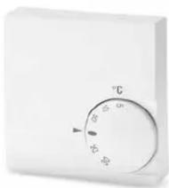
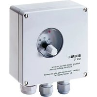
Close-up of a white rectangular electronic device with a circular dial and indicator lights (no text or symbols visible)Achtung!
Das Gerät darf nur durch einen Elektro-Fachmann geöffnet und gemäß dem Schaltbild im Gehäusedeckel bzw. dieser Anleitung installiert werden. Dabei sind die bestehenden Sicherheitsvorschriften zu beachten.
Um Schutzklasse II zu erreichen, müssen entsprechende Installationsmaßnahmen ergriffen werden.
Dieses unabhängig montierbare Gerät dient der Regelung der Temperatur ausschließlich in trockenen und geschlossenen Räumen, mit üblicher Umgebung. Das Gerät ist gemäß VDE 0875 T.14 bzw. EN 55014 funkentstört und arbeitet nach der Wirkungsweise 1Y (EN 60730).
1. Anwendungsbereich
Verwendung:
Der elektronische Temperaturregler mit Triac-Ausgang kann verwendet werden für:
- Warmwasser-Heizanlagen in Verbindung mit elektrothermischen Stellantrieben (stromlos geschlossen oder offen) wie, Warmwasser-, Konvektor- oder Fußbodenheizung.
- Elektrische Konvektor-, Fußboden-, Decken- und Speicherheizung in Verbindung mit einem Schütz
• Nachtstromspeicherheizung
• Klimaanlagen (nur Kühlen)
Merkmale
• Temperaturabsenkung
- Wirkrichtung umschaltbar, zur Verwendung von Stellantrieben: Stromlos offen oder stromlos geschlossen
• Umschaltbar zwischen Heizen und Kühlen
- Varianten mit Schalter Tag/Nacht/Uhrbetrieb
- Varianten mit Lampe „Wärmeanforderung“
- Varianten für AC 24 V oder AC 230 V
- Anschluß eines externen Fühlers möglich
- mit elektronischem Lastschalter daher: geräuschlos
langlebig
- Zur direkten Wandmontage oder auf UP-Dosen
2. Funktionsbeschreibung
Variante ohne Schalter (Typ RTRt-E 525 80/84/86)
Die gewünschte Temperatur wird durch den Einstellknopf festgelegt. Der Regler schaltet die zugehörige Wärmequelle (Stellglied) solange, bis die Temperatur erreicht ist.
Uhr-Betrieb (durch externe Schaltuhr);
Die am Einstellknopf gewählte Temperatur wird um ca. 3 °C reduziert, wenn der Kontakt an Klemme 8 geschlossen ist.
Variante mit Schalter (Typ RTRt-E 525 81)
Dauerhaft Tagtemperatur:
Die gewünschte Temperatur wird durch den Einstellknopf festgelegt. Der Regler schaltet die zugehörige
Wärmequelle (Stellglied) solange, bis die Temperatur erreicht ist.
Dauerhaft Nachttemperatur:
Die am Einstellknopf gewählte Temperatur wird dauerhaft um ca. 3 °C reduziert.
Uhr-Betrieb (durch externe Schaltuhr):
Die am Einstellknopf gewählte Temperatur wird um ca. 3 °C reduziert, wenn der Kontakt an Klemme 8 geschlossen ist.
Varianten mit Lampe:
Die Lampe leuchtet, wenn der Regler Wärme anfordert.
Wärmeanforderung des Reglers:
Über den eingebauten Triac wird die Wärmequelle (Stellglied) mit unterschiedlich langen Impulsen geschaltet (Puls-Weiten-Modulation). Die Länge der Impulse ist abhängig von der Differenz zwischen eingestellter zu tatsächlicher Raumtemperatur. Die Summe der Zeiten von Impuls und Pause beträgt ca. 5...10 Min.
Bei großen Temperaturdifferenzen schaltet der Regler dauerhaft ein bzw. aus z. B. bei Temperaturabsenkung.
Umschalten der Wirkrichtung (nur RTRt-E 525 80/81):
Über die Steckbrücke kann eingestellt werden ob der Regler Stellantriebe „stromlos geschlossen“ oder „stromlos offen“ ansteuern soll. Der Regler ist auch geeignet zur Klimatisierung, für Anwendungen „nur Kühlen“.
| Steckbrücke(rechts oben | für Ventile | wenn Ventilstromlosgeschlossen |
| rechts gesteckt(Auslieferzustand) | stromlosgeschlossen | Heizen |
| links gesteckt stromlos offen Kühlen | ||
Varianten ohne Steckbrücke
(z.B. RTRt-E 525 84/86):
Wirkrichtung siehe Deckelschaltbild.
3. Montage
Der Regler soll an einer Stelle im Raum montiert werden, die:
- für die Bedienung leicht zugänglich ist.
- frei von Vorhängen, Schränken, Regalen etc. ist
- freie Luftzirkulation ermöglicht
- frei von direkter Sonneneinstrahlung ist
- frei von Zugluft ist (öffnen von Fenstern und Türen)
- nicht direkt von der Wärmequelle beeinflußt wird
- nicht an einer Außenwand liegt
• ca. 1,5m über dem Fußboden liegt.
Montage direkt auf UP-Dose, oder mit Adapter-rahmen ARA 1E.
Elektrischer Anschluß
Achtung! Stromkreis spannungsfrei schalten
Anschluß in folgenden Schritten:
- Abziehen des Temperatur-Einstellknopfes
- Mit einem Schraubendreher den Befestigungshaken nach außen drücken.
• Abnehmen des Gehäuseoberteils - Anschluß gemäß Schaltbild (s. Gehäuseoberteil) durchführen
- Hinweise beachten
Anschluß des Fernfühlers:
• Entfernen des internen Fühlers
(s. Bild)
- Anschluß des externen Fühlers an die Klemmen 11, 12 siehe Schaltbild im Gerät).
Der Fernfühler kann mit einem 2-adrigen Kabel bis auf ca. 50 m verlängert werden (230 V-Kabel erforderlich). Enge Parallelführung mit Netzleitungen sollte vermieden werden.

4 Besondere Hinweise
- Der Triac ist nicht geschützt. Überlast oder Kurzschluß der Last führt zur Zerstörung des Triac.
- Das Abschalten der Last erfolgt im Strom-Nulldurchgang, dadurch kann ein Schütz ohne Zusatzmaßnahmen direkt angesteuert werden.
- Während der Einschaltdauer ist der Triac ständig leitend, es erfolgt kein Phasenanschnitt.
5 Funktionsdiagramm
Verlauf der relativen Einschaltdauer (Tastverhältnis) in Abhängigkeit von der Temperatur für:
Brücke rechts: „stromlos geschlossen“, Heizen Brücke links: „stromlos offen“, Kühlen

line
| Signal Waveform | Rel. Einschaltdauer / % | |---|---| | dauernd aus | 0 | | dauernd ein | 100 | | Sollwert | 0 | | Raum-temp. | 0 | | Triac Signal | 0 | | Solswert | 0 | | Raum-temp. | 100 | | Triac Signal (bottom) | 0 | | Solswert (bottom) | 0 | | Raum-temp. (bottom) | 100 | | Triac Signal (top) | 0 | | Solswert (top) | 0 | | Raum-temp. (top) | 100 | The chart displays two line plots: left plot shows 'rel. Einschaltdauer / %' with a linear trend from 100 to 0 across the x-axis, while right plot shows 'rel. Einschaltdauer / %' with a linear trend from 0 to 100 across the same x-axis, both based on the same y-axis label 'dauernd aus'. The bottom trace below is a triangular waveform indicating the triangular signal amplitude.6 Technische Daten
| Typ RTRt-E 525 80/81/84/86 | |||||||
| Artikel-Nr. | 515 | 1901 | 515 | 1905 | 515 | 1911/14 | 515 |
| Versorgunsspannung AC 24V (20 ... 30 V, 50/60 Hz) AC 230 V (195) | ... 253 V, 50/60 Hz | ||||||
| Schaltstrom | |||||||
| dauernd (siehe Hinweis) | 0 ... 1,2 A (cos φ =1)* | 0 ... 0,8 A (cos φ =1)* | |||||
| 0 ... 0,7 A (cos φ =0,6)* | 0 ... 0,5 A (cos φ =0,6) | ||||||
| kurzzeitig für 2 s max. 5 A max. 5 A | |||||||
| Schaltbare Stellantriebe | 5 (3 W elektrothermisch) | 5 (3W elektrothermisch) | |||||
| Schaltspannung | = Betriebsspannung | ||||||
| Temperaturbereich | 5 ... 30 °C | ||||||
| Bereichseinengung | im Einstellknopf | ||||||
| Temperaturabsenkung | ca. 3 K | ||||||
| Zyklusdauer | 5 ... 10 Min. (Summe von Ein- und Auszeit der Puls-Weiten- Modulation) | ||||||
| Ausgang | Triac | ||||||
| Temperaturfühler | intern | ||||||
| Fernfühler(optional) | Typ 193 720 Länge 4 mTyp 190 021 (für Wandmontage) beide verlängerbar auf 50m | ||||||
| Proportionalband | 1,5 K (Bei dieser Istwertänderung ändert sich die Stellgröbenahezu linear zwischen 0 und 100%, außerhalb diesesBereiches ist ständig ein bzw. aus) | ||||||
| Schutzart Gehäuse | IP 30 | ||||||
| Schutzklasse | II (nach entsprechender Installation, siehe Achtung) | ||||||
| Betriebstemperatur | -10 ... 40°C | ||||||
| Lagertemperatur | -25 ... 70°C | ||||||
| Gewicht | ~75 g | ||||||
* Hinweis: Bei umgekehrter Wirkrichtung (RTRt-E 525 84 oder Brücke links bei RTRt-E 525 80/81) und Betrieb ohne Fernfühler sollte der Dauerstrom 0,5 A nicht überschreiten.
7 Schaltbild
RTRt-E 525 80/81

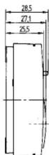
8 Maßbild

RTRt-E 525 84/86

468 931 012 930-02
EBERLE
Installation and operating instructions
Electronic room temperature controller with Triac output
RTRt-E 525 80 /81/ 84 /86
natural_image
Close-up of a white industrial air conditioner unit with a circular dial and temperature scale (no text or symbols visible)Warning!
This unit must not be opened and installed except by authorized persons and in compliance with the circuit diagram provided inside the cover. It is mandatory in all work on the unit to observe the current safety regulations. In order to classify for protection class II it is necessary to take adequate installation measures.
This separately mounted unit is designed for temperature control exclusively in dry and closed rooms with standard environment. The unit features radio-interference suppression
in compliance with VDE 0875 T.14 and EN55014, respectively and works according to operating principle 1 Y (EN 60730).
1. Applications
The electronic thermostat with Triac output can be used for:
- Control of hot water heating systems in conjunction with electrothermal actuators (closed or open de-energised) such as hot water, convector or floor heating systems.
• Electric convector, floor, ceiling and storage heating systems connected with contactor
• Night storage heating
• Air Conditioning equipment (cooling only)
Features
• Temperature set-back
- Direction of efficiency changeable for application of actuators n/o or n/c
- Changing of heating/cooling mode
• Available variants
→ mode selector switch comfort/set-back/automatic
→ indication lamp "calling for heat"
⇒ operating voltage AC 24 V or AC 230 V
- Remote sensor optional
• High life expectancy and noiseless due to
electronic load interruptor
2. Function description
Variant without mode selector switch
(Type RTRt-E 525 80/84/86)
Comfort temperature will be set by means of externally visible setting knob. Controller contact switches the associated heath source until the set temperature is reached.
Automatic mode (via external timer)
The adjusted temperature at the setting knob will be reduced of approx. 3^ C when contact at terminal 8 is closed.
Variant with mode selector switch
(Type RTRt-E 525 81)
Permanent comfort (day) temperature.
The required temperature can be adjusted at the setting knob. Controller contact switches the associated heat source until the set temperature is reached.
( Permanent set-back temperature
The adjusted temperature at the setting knob is continuously reduced by about 3^ .
Automatic mode (via external timer)
The adjusted temperature at the setting knob will be reduced of approx. 3^ C when contact at terminal 8 is closed.
Variant with indication lamp
This lamp indicates “controller calls for heat”
Heat demand of the controller
Via the incorporated Triac the heat source will be switched in the form of pulses of varying lenght (PWM). The length of the pulses depends on the difference between set and actual room temperature.
The sum of pulse and pause times can be approx. 5 to 10 minutes.
If there are large temperature differences, the controller will switch ON or OFF permanent, e.g. when changing over to temperature set-back mode.
Changing of direction of the efficiency
(only type RTRt-E 525 80/81
By means of the plug-in jumper there can be selected the control of n/c actuators or n/o actuators. This controller can also be used for “cooling only” applications.
| Plug-in jumper(right side of board) | for valves | if valvesn/c |
| right side plugged(as-delivered condition) | n/c heating | |
| left side plugged | n/o | cooling |
Variant without plug-in jumper
(type RTRt-E 525 84/86)
Direction of efficiency : see wiring diagram inside cover.
3. Installation
The controller should be arranged in a place within the room which:
• is easily accessible for operation
- is free from curtains, cupboards, shelves, etc.
• enables free air circulation
• is free from direct sun radiation
- is free from draughts (e.g. opening of windows and doors)
• is not affected directly by the source of heat
• is not located on an external wall
• is located approx. 1,5 m above floor level
Mounting directly on conduit box or with adapter frame ARA 1E.
Electric connection
Warning! Disconnect electric circuit from supply.
Proceed as follows:
- pull off temperature setting knob
- open screw
- remove housing cover
- make connection in compliance with wiring diagram (see housing cover).
- watch notes
Remote Sensor
- Remove internal sensor as shown
- Connect external remote sensor to terminals 11 and 12 according to wiring diagram (inside cover)
- The sensor cable is
extendable up to a
lenght of max. 50 m
Please use a two-core
230 V cable with a
cross section of 1.5 mm².
The sensor cable (F 193 720) should be installed into a protection tube (pocket). This facilitates later replacement.
Warning! Sensor cables carry operating voltage.

4. Important notes
- The Triac is not protected. Overload or short-circuit of the load will damage the Triac.
- The disconnection of the load takes place at current-zero, so that a contactor directly can be controlled without any supplementary steps.
- During the ON period the Triac is conductive permanent. There happens no phase section.
5. Function diagram
Characteristic of impulse pause ratio depending on temperature
plug-in jumper – right side: "NC", heating plug-in jumper – left side "NO", cooling
rel. capacity / %

line
| Time (min) | Intensity | |---|---| | 0 | 100 | | 1 | 100 | | 2 | 50 | | 3 | 25 | | 4 | 10 | | 5 | 0 | The chart displays a single line representing a constant value of 100 across room temperature from room temp. The lower panel shows the Triac signal waveform for type RTRt-E 525 86 this function only.
line
| Room temp. | Set value | |---|---| | 0 | 0 | | 100 | 100 |6. Technical data
Type RTRt-E 525 80/81/84/86
Article No. 515 1901 515 1905 515 1911/14 515 1903
Operating voltage AC 24 V (20...30 V), 50/60 Hz AC 230 V (195...253 V), 50/60 Hz
Switching current
| permanent (see note) | 0...1,2 A ( = 1 )* | 0...0,8 A ( = 1 )* |
| 0...0,7 A ( = 0,6 )* | 0...0,5 A ( = 0,6 )* | |
| short-time for 2 sec. | max. 5 A | max. 5 A |
| Number of actuators | 5 (3 W electro thermal) | 5 (3 W electro thermal) |
| each to be connected | |
| Switching voltage | corresponding to operating voltage |
| Temperature range | 5 to 30°C |
Range limitation inside setting knob
| Temperature set-back | approx. 3 K |
| Cycle period | 5...10 min (sum of PWM ON and OFF times) |
| Output | Triac |
Temperature sensor integral
Remote sensor (optional) type F 190 021 (wall mounting)
type F 193 720 length 4 m
both extendable up to 50 m
Sensor characteristics 42KΩ at 20°C 36 kΩ at 20°C
Proportional band 1.5K
Protection class of housing IP 30 insulated
Degree of protection II (see Warning!)
Ambient temperature -10...+40°C without condensation
Storage temperature -25...+65°C
Weight \~75 g
* Note: At reversed direction of efficiency (for RTRt-E 525 84 or jumper plugged left side for RTRt-E 525 80/81) and at operation without remote sensor, the permanent switching current should not exceed 0.5A!
7 Wiring diagram
RTRt-E 525 80/81

8 Dimensions
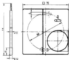
RTRt-E 525 84/86




- Achtung!
- Anwendungsbereich
- Verwendung:
- Merkmale
- Funktionsbeschreibung
- Variante ohne Schalter (Typ RTRt-E 525 80/84/86)
- Variante mit Schalter (Typ RTRt-E 525 81)
- Varianten mit Lampe:
- Wärmeanforderung des Reglers:
- Umschalten der Wirkrichtung (nur RTRt-E 525 80/81):
- Varianten ohne Steckbrücke
- Montage
- Elektrischer Anschluß
- Anschluß des Fernfühlers:
- Besondere Hinweise
- Funktionsdiagramm
- Schaltbild
- EBERLE
- Warning!
- Applications
- Features
- Function description
- Variant without mode selector switch
- (Type RTRt-E 525 80/84/86)
- Variant with mode selector switch
- (Type RTRt-E 525 81)
- Heat demand of the controller
- Changing of direction of the efficiency
- (only type RTRt-E 525 80/81
- Variant without plug-in jumper
- (type RTRt-E 525 84/86)
- Installation
- Electric connection
- Remote Sensor
- Important notes
- Function diagram
- Technical data
- Wiring diagram
Marque : Eberle
Modèle : RTRT-E 52586
Catégorie : Thermostat