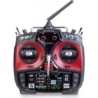
mz-24 PRO - Jouet radiocommandé GRAUPNER - Notice d'utilisation et mode d'emploi gratuit
Retrouvez gratuitement la notice de l'appareil mz-24 PRO GRAUPNER au format PDF.


| Type de produit | Émetteur de radiocommande pour modèles réduits |
| Marque | Graupner |
| Modèle | mz-24 PRO |
| Nombre de voies | 24 voies |
| Fréquence | 2,4 GHz FHSS |
| Alimentation émetteur | Accu LiPo 3S 11,1 V 4500 mAh intégré |
| Dimensions (L x l x h) | 220 x 120 x 280 mm |
| Poids | 820 g (sans batterie) |
| Affichage | Écran tactile couleur TFT 4,3 pouces |
| Fonctions principales | Télémétrie, mixages programmables, courbes de gaz, gyroscope intégré, mémoire pour 30 modèles |
| Entretien et nettoyage | Nettoyer avec un chiffon doux et sec. Ne pas utiliser de solvants. |
| Sécurité | Ne pas exposer à l'humidité. Éteindre après utilisation. Utiliser uniquement des chargeurs adaptés. |
| Pièces détachées et réparabilité | Pièces disponibles via service après-vente Graupner ou revendeurs agréés. |
| Informations générales | Logiciel mise à jour via carte microSD. Compatible avec récepteurs Graupner HoTT. |
FOIRE AUX QUESTIONS - mz-24 PRO GRAUPNER
Questions des utilisateurs sur mz-24 PRO GRAUPNER
0 question sur cet appareil. Repondez a celles que vous connaissez ou posez la votre.
Poser une nouvelle question sur cet appareil
Téléchargez la notice de votre Jouet radiocommandé au format PDF gratuitement ! Retrouvez votre notice mz-24 PRO - GRAUPNER et reprennez votre appareil électronique en main. Sur cette page sont publiés tous les documents nécessaires à l'utilisation de votre appareil mz-24 PRO de la marque GRAUPNER.
MODE D'EMPLOI mz-24 PRO GRAUPNER
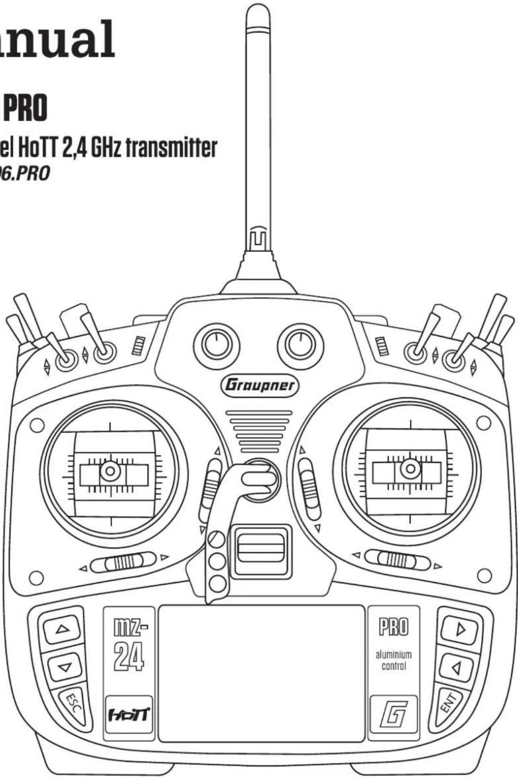
Manual
mz-24 PRO
12 channel HoTT 2,4 GHz transmitter
No. S1006.PRO
Index
Introduction....5
Service Centre ....5
Intended use 6
Target group....6
Package content 6
Technical Data 7
Declaration of conformity....7
Symbols explication 8
Safety notes....8
For your safety by handling the transmitter 9
For your safety by handling the battery....10
Description of the transmitter....12
Control elements on the transmitter....12
Connection on the back side....13
Data socket....13
Ear phones port....13
Card slot....13
Mini-USB connection....14
DSC socket....15
Charging socket 15
Fixtures 15
Attaching the transmitter neck-strap....15
Commissioning....16
Settings by the first use....16
Switch on transmitter....16
Adjusting the control stick....17
Control sticks length adjustment....18
Transmitter power supply 18
Low voltage warning....18
Binding....18
Charging the transmitter battery 18
Removing transmitter battery....19
Inserting the transmitter battery 19
Charge possibilities....19
Battery use timer in the display 20
Use and menu functions....21
Operation of the key field....21
Entry lock 21
Digital trim 22
Display 22
Operation 22
Indications active/inactive fields 22
Display symbols....23
Firmware update 24
Transmitter software update....24
Notes on environmental protection 25
Care and maintenance....25
Warranty certificate....25
Introduction
Thank you very much for purchasing the Graupner mz-24 PRO HoTT transmitter.
Read this manual carefully to achieve the best results with your transmitter and first of all to safely control your models. If you experience any trouble during operation, take the instructions to help or ask your dealer or Graupner Service Centre.
The transmitter is delivered with English firmware. To switch the transmitter to your local language, you must download the appropriate firmware on their transmitter. Please read the chapter "Firmware Update"

NOTICE
This manual is composed by two parts. Part 1 is contained in the product's package content. Part 2 can be found in its last version on www.graupner.com by the related item page.
Due to technical changes, the information may be changed in this manual without prior notice. Be always updated by checking periodically on our website, www.graupner.com to be always uptodate with the products and firmwares.
This product complies with national and European legal requirements.
To maintain this condition and to ensure safe operation, you must read and follow this user manual and all the safety notes before using the product!

NOTICE
This manual is part of that product. It contains important information concerning operation and handling. Keep these instructions for future reference and give it to third person in case you gave the product.
Service Centre
Graupner-Zentralservice Deutschland UG
Süd Nord Strasse 63, D-26907 Walchum, Germany www.graupner-service.de
Servicehotline
(+49) (0) 59 39 - 959 919 0
Korea Center
202-809, 18, Bucheon-ro 198beon-gil, Bucheon-si, Gyeonggi-do, Korea 14557
(+82) 32 - 623 - 0733
Americas Service Center
Control Hobbies 3450 Palmer Drive, Suite 4-277, Cameron Park, CA. 95682, USA www.controlhobbies.com
Servicehotline
+1-877-238-0911
Graupner im Internet
For the service centers outside the above countries please refer to our website www.graupner.com
Intended use
This remote-control system may only be used for the purpose specified by the manufacturer for operation of remote control models without passengers. Any other type of use is impermissible and may damage the system and cause significant property damage and/or personal injury. No warranty or liability is therefore offered for any improper use not covered by these provisions.
Read through this entire manual before you attempt to install or use the transmitter.
Graupner constantly works on the development of all products; we reserve the right to change the item, its technology and equipment.
Target group
The product is not a toy. It is not suitable for children under 14 years. The operation of the mz-24 PRO HoTT transmitter must be performed by experienced modelers. If you do not have sufficient knowledge about dealing with radio-controlled models, please contact an experienced modeler or a model club.
Package content
① Transmitter mz-24 PRO HoTT
① Transmitter battery
① Battery charger
① Receiver (optional)
USB Adapter/Interface
USB cable
① Adapter cable
① Transmitter strap
① Pencil for display use
① Transmitter manual (Part 1)
① Receiver manual (optional)
⑦ Micro SD card
Micro SD card adapter
① Transport case
The programming manual (manual part 2) can be found in its last version on www.graupner.com by the related item page.
Technical Data
Transmitter mz 24 PRO HoTT
| Frequency band | 2,4 ... 2,4835 GHz |
| Modulation | FHSS |
| Transmitting power | 100 mW EIRP |
| Control functions | 12 functions of which 4 can be trimmed |
| Temperature range | -10 ... +55 °C |
| Antenna | Can be turned and folded |
| Operating voltage | 3,4 ... 6 V |
| Power consumption | approx. 540 mA |
| Dimensions | approx. 194 x 287 x 112 mm |
| Weight | approx. 840 g with transmitter battery |

Note
The technical data of the optional receiver are available in the manual included in the receiver package content.
Symbols explication

Always observe the information indicated by this warning sign. Particularly those which are additionally marked with the CAUTION or WARNING. The signal word WARNING indicates the potential for serious injury, the signal word CAUTION indicates possibility of lighter injuries.

The signal word Note indicates potential malfunctions. ATTENTION indicates potential damages to objects.
Safety notes

These safety instructions are intended not only to protect the product, but also for your own and other people's safety. Therefore please read this section very carefully before using the product!
⑤ Do not carelessly leave the packaging material lying around, since it might become a dangerous toy for children.
⑤ Persons, including children, with reduced physical, sensory or mental capabilities, or lack of experience or knowledge, or not capable to use safely the transmitter must not use the transmitter without supervision or instruction by a responsible person.
Operation and use of radio-controlled models needs to be learnt! If you have never operated a model of this type before, start carefully and make yourself familiar with the model's reactions to the remote control commands. Proceed always responsibly.
⑤ Before you start using the remote control model, you have to check the further relevant laws and regulations. These laws you must obey in every case. Pay attention to the possibly different laws of the countries.
⑤ The insurance is mandatory for all kinds of model operation. If you already have one, so please inform yourself if the operation of the respective model is covered by your insurance. If this is not the case, conclude a special liability insurance policy for models.
Inform yourself before flying your model on which maximum altitude you can fly in the uncontrolled airspace over the starting position and do not exceed it.
⑤ Protect all equipment from dust, dirt, moisture. All equipment must be protected from vibration as well as excessive heat or cold. The models may only be operated remotely in normal outside temperatures such as from -10°C to +55°C .
⑤ Always perform a range test and functional test on the ground before you use your model! Only so you ensure safe operation! To know how to perform a range check, please read Part 2 of the manual.
⑤ Use all HoTT components only with the current software version.
Save by each use of your model the log file. With a log file it is possible to trace possible occurring technical failures. Only so any claims can be considered.
For your safety by handling the transmitter

WARNING
Also while programming the transmitter, make sure that a connected motor cannot accidentally start. Disconnect the fuel supply or drive battery beforehand.

CAUTION
Risk of fire! Avoid every kind of short-circuit in all sockets of the transmitter! Use only the suitable connectors. In no case the electronic component of the transmitter may be changed or modified. Due to licensing reasons, any reconstruction and/or modification of the product is prohibited.

Note
During transport protect the model and the transmitter from damages.
For your safety by handling the battery

CAUTION
⑤ Protect all equipment from dust, dirt, moisture. Only use in dry locations.
Do not use any damaged battery. Risk of injury!
⑤ Any alterations to the battery can cause serious injury. Risk of fire!
⑤ Batteries may not be heated, burned, short-circuited or charged with excessive current or with reversed polarity.
⑤ While they are being charged, the batteries must be placed on a non-flammable, heat-resistant and non-conductive surface. Combustible or highly flammable objects are to be kept away from the charging area. Batteries must be monitored while they are being charged.
⑤ The maximum quick charging current specified for the respective cell type may not be exceeded.
⑤ If the battery heats up above 60° C while it is being charged, stop charging and let the battery cool down to approximately 30 - 40° C.
⑤ Never charge batteries that have already been charged, are hot or are not fully discharged. If a cell in a battery pack has become particularly hot following a quick-charge process, this may indicate a defect in that cell. Do not use the battery pack any more!
⑤ The batteries must not be modified. Do not directly solder or weld the cells.
⑤ If handled improperly, there is a danger of fire, explosion, irritation and burns. To extinguish a fire use: water, CO 2 , sand.
⑤ Leaked electrolyte is caustic and should not be touched or come into contact with your eyes. In case of emergency, rinse with a large quantity of water and consult a Med. Doctor.
⑦ Always charge the battery fully.
⑤ The maximum charging current permitted may not be exceeded.
⑤ Never leave the charger unattended when it is connected to the power supply.
⑤ Batteries may only be charged in rooms fitted with smoke detector.
Special instructions
To charge and discharge batteries, only use specifically designed chargers/dischargers with balancer connector.
⑤ The white connector (cell count + 1 pole) is designed for the connection to a LiPo balancer or a battery charger as a single cell charger with a manual cell balancer. Always charge the battery with the balancer connector.
Safety notes for stocking batteries
⑤ Batteries may only be stored in non completely discharged condition.
⑤ Batteries may only be stored in dry rooms with an ambient temperature of +5°C to +25°C.
⑤ Stock the LiPo batteries with a cell voltage of about 3,8V. If the cell voltage falls below 3 V, then the battery must be necessarily charged. Deep discharge and storage in discharge status (cell voltage < 3V) make the battery useless.
① Charge and transport your batteries always in a safety bag.
Description of the transmitter
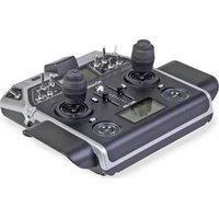
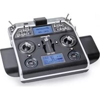
Control elements on the transmitter
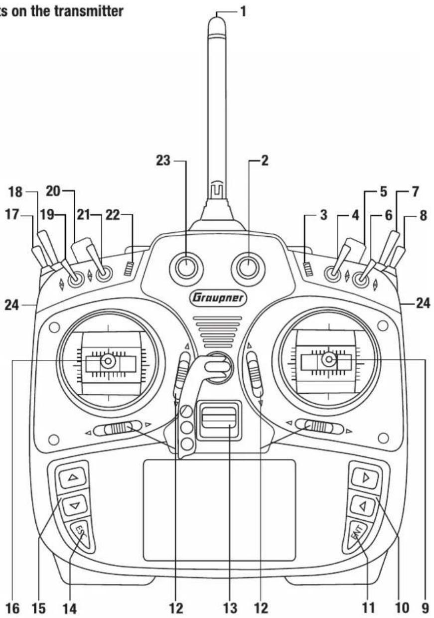
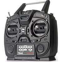
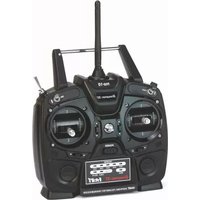
| 1 | Antenna |
| 2 | Proportional dial DV3 |
| 3 | INC/DEC buttons DT2 |
| 4 | Switch SW 3 |
| 5 | Proportional dial DV4 |
| 6 | Switch SW 4 |
| 7 | Switch SW 8 |
| 8 | Switch SW 7 |
| 9 | Right control stick |
| 10 | Alternative adjusting buttons |
| 11 | ENTER button |
| 12 | Trim |
| 13 | On/off switch |
| 14 | ESC button |
| 15 | Alternative selection buttons |
| 16 | Left control stick |
| 17 | Switch SW 5 |
| 18 | Switch SW 6 |
| 19 | Switch SW 1 |
| 20 | Proportional dial DV1 |
| 21 | Switch SW 2 |
| 22 | INC/DEC buttons DT1 |
| 23 | Proportional dial DV2 |
| 24 | SL1/SL2 lever, back, left, right |
Connection on the back side

Data socket
The data socket is suitable for connection of an optional smart box.
You can find accessories on www.graupner.com
Ear phones port
Though this interface both acoustic signals and voice messages are emitted.
The volume can be controlled by "Voice volume" and "Signal volume" in the general settings.
Card slot
The card slot is suitable for micro SD memory card.
Micro SD cards up to 2 GB and micro SDHC up to 32 GB are compatible memory cards.
Our recommendation: For a normal use a memory card with a storage capacity of up to 4 GB is sufficient.
Inserting and removing the memory card step by step:
Switch off the transmitter.
The memory card slot is located over the battery case under the back side cover of the transmitter.
To insert:
Push the SD card as deep as you need to win the spring resistance of the slot.
To remove:
Push the SD card slightly toward the card slot to unlock it and then remove it.
The included memory card is ready for use as soon as the transmitter is switched on. In the display appears the symbol of a memory card.
Otherwise, folders are created on the memory card (represented in the transmitter display by a blinking memory card symbol). When the animation finishes, the inserted memory card is ready for use.
Data recording/Data saving
The data recording in the SD card is linked to the flight timer. If it is started, the data recording starts as well and it stops when the flight timer is stopped.
The data writing on the memory card is remarked by the blinking memory card symbol.
After the installation of the memory card, there is a folder structure in it. These folders are actually empty.
Finally, the log files are saved in subfolders called "Modelname" named according to the structure 0001_year-month-day.bin. If a model memory is still nameless, the corresponding log files are saved in a subfolder entitled "NoName".
In the folder "Models" are saved the exported model memories.
The data can be evaluated on a compatible computer using the programs found on the downloads page for the transmitter under www.graupner.com
You can connect the memory card to your PC by using a memory card reader. Copy the data downloaded from the transmitter page on the web site in the related folder of the memory card. Insert the memory card in your transmitter.
Mini-USB connection

Note
The mini USB socket is not suitable for flight simulator connection.
Through this socket it is possible to connect the transmitter to a PC. The software that the computer needs as well as the appropriate USB driver can be found on the download page on www.graupner.com for the respective product.
DSC socket

Connection socket for flight simulator or T/P systems
Trough a DSC cable the port can serve to use the transmitter with a simulator o to connect it with another one in Teacher/pupil mode.
Switch the DSC mode in the "General settings menu". In this way you can change the base display too. Right in the display appears "DSC".
To ensure a correct DSC connection, observe the following:
- Perform any necessary adaptations in the menu.
- When using the transmitter with a flight simulator or during the teacher-pupil operation, set the On/Off switch always on the "Off" position. Connect one end of the DSC cable in the DSC port of the transmitter.
- Switch the transmitter on.

ATTENTION!
When your transmitter is directly connected to a desktop computer by a connecting cable (DSC cable) and/or a computer interface is connected to your simulator, the transmitter may be destroyed by electrostatic discharge. This type of connection should therefore only be used if you protect yourself from electrostatic discharge while operating the simulator by wearing a commercially available grounding armband. Graupner therefore strongly recommends only using wireless simulators.
Charging socket
Through the charging socket you can charge the transmitter battery using the supplied plug-in charger.
DO NOT USE PLUG-IN CHARGERS BY OTHER MANUFACTURERS OR OTHER CHARGERS.
The maximum charge current is 1,5 A.
More information are available in the section "Charging the transmitter battery".
Fixtures
Attaching the transmitter neck-strap
On the upper side of the transmitter there is an orientable eyelet which can be used to hook a neck-strap.
Commissioning
Settings by the first use
Switch on transmitter
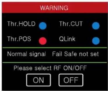
When you switch on the transmitter the position of the servos connected to the outputs 1 (plane) and 6 (heli) are checked. If the servo position is out of the idle range, the RF module will remain Off.
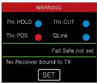
If this is not the case, the RF module will be activated and the image on the left will appear.
At the same time a warning alarm will be emitted.
You now have the option of waiting a few seconds until the display disappears or maintaining the RF transmissions by manually tapping the ON button, or switching them off by tapping the OFF button.
In the base display you can check if the RF module is on or off. The related symbol is on the upper left side of the display.
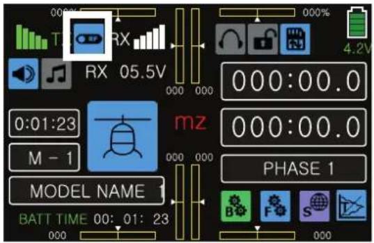
The red "RX" and green "TX" on the left and right of this switch symbol mean that the currently active model memory has once been linked to a Graupner-HoTT receiver but is presently not linked.
If there is a connection, it will be indicated by a green colored numeric indication of the actual voltage of the receiver power supply in the field near "RX" and "TX".
If the transmitter is turned on while the RF transmission is off, all of this information is not displayed, and the high-frequency switch symbol is gray.
If it appears the display represented on the left after switching the transmitter on, the currently active model memory is not linked to any receiver. By pushing the SET button you arrive to the "Transmitter settings" menu, in which you can bind the transmitter.
Adjusting the control stick
Both the left and right control sticks can optionally be set from neutralizing to non-neutralizing and vice versa. The control sticks' restoring force can also be adjusted.
The related adjusting system is on the back of the transmitter in the battery compartment, under the rubber covers, and under the side grips attached with double-sided adhesive tape. Make the desired adjustment by turning the relevant setscrew using a standard cross screwdriver.
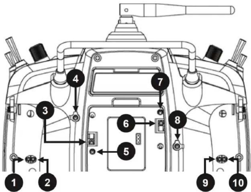
1 and 2 / 9 and 10
Adjust the braking force with the outermost of the two screws, and adjust the strength of the control stick ratchet using the innermost screw.
4 and 5 / 7 and 8
Adjust the return force of the control direction by turning the relevant setscrew using a standard cross screwdriver.
3 and 6
To change the standard setting of the control sticks, turn the screw toward the inside of the transmitter until the relevant control stick can move freely from stop to stop, or turn it outward until the control stick resets itself independently.
Control sticks length adjustment
Length of both control stick can be adjusted. Hold down the bottom half of the knurled grip, and loosen the screwed connection by turning the top part:
You can now lengthen or shorten the control stick by screwing it up or down. Then clamp the top and bottom part of the grip by rotating them against each other.
Transmitter power supply
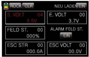
The transmitter battery voltage should be monitored in the LCD display during operation. Once the adjustable voltage in the "battery warning threshold" is reached in the "Etc.Set" submenu of the system menu, a standard 3.6V (lith.) for the mz-24 PRO HoTT transmitter, a warning beep sounds, and the following window appears in the display:
Now at the latest, stop operation and recharge the transmitter battery!
Binding
Explications about the binding process can be found in the Part 2 of the manual.
For a transmitter commissioning the receiver must be bound to the transmitter. This binding process is necessary for the operation of the model!
The exact sequence of the binding operation is described in the section "Binding" in the Part 2 of the manual and in the respective receiver manual. Note: The procedure will be different for the different receiver types.
Charging the transmitter battery

WARNING
⑤ Protect the charger from dust, dirt, moisture, vibrations and other foreign parts.
⑤ The charger should always be supervised during charge and it should be used only in rooms fitted with a smoke detector.
⑤ The charger and the battery to be charged must be placed on a non-combustible, heat-resistant and non-conducting surface during operation. Do not use the charger near easily flammable materials.
① Verify if the charger is suitable for your battery type.
① Always connect only one battery to the battery charger output.
⑤ Use only batteries and battery cables with suitable connectors and reverse polarity protection. Make sure that the polarity is correct.
⑤ After the charge is complete disconnect the charger from the power source.
⑥ The battery charger can be used only in dry spaces.
⑤ A wet charger, even if re-dried, should no longer be used. Never use a damaged battery charger.
⑤ Due to licensing reasons, any reconstruction and/or modification of the product is prohibited.
⑤ Be sure that during charge the charger is not covered. The ventilation slots must be free.
Removing transmitter battery
Remove the battery case cover.
Then remove and disconnect the battery plug.
Lift the battery and pull it away from the Velcro tape.
Inserting the transmitter battery
The battery connection is protected by two beveled edges from polarity reversal when plugging in.
Plug the battery connector carefully and pay attention to the correct polarity.
Charge possibilities

CAUTION
The transmitter must be turned off while the entire charging process.
You have two charge possibilities:
- By removing the battery from its case and charging it with a charger
Removing transmitter battery
Remove the battery case cover.
Then remove and disconnect the battery plug.
Lift the battery and pull it away from the Velcro tape.
Charge the battery following the charger manual.
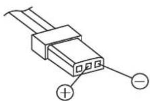
Inserting the transmitter battery
Connect the battery plug in the transmitter socket. Make sure that the polarity is correct. Pay attention to the respective "+" and "-" symbols near the socket.
Red = +
Black / brown = -
Place the battery into its compartment and close the cover.

2. Through charge socket and charge with AC charger
CAUTION
Do not use plug-in chargers by other manufacturers or chargers that were designed for different battery types. Transmitter and battery can be damaged. Risk of fire!
Make sure that the transmitter is switched off. The transmitter must be turned off while the entire charging process.
Connect the jack of the included AC charger to the charge socket.
A completely discharged battery requires approx. 15 hours to be charged.

Polarity of the mz charging socket
The charging cables available on the market by other manufacturers frequently have different polarities. For this reason, you should only use original Graupner charging cable.

NOTE
The charging socket comes standard with a protection switch that protects against polarity reversal. Original Graupner automatic chargers recognize the battery charge. In order to prevent damage to the protection switch and to the other components, charging current should never exceed 1 A.
Battery use timer in the display
The use timer is shown in the lower left part of the display in green.
The battery use time is added at every use. Every time that the voltage is higher than the use before the timer is reset to "00:00:00". This happens only if the voltage is at least 0,3V higher then before, it means it happens through a battery charge.
Use and menu functions
Operation of the key field
The main operation of the transmitter is made by using the touch screen display. In some cases it is possible to use the buttons on the sides of the display.
Keys left of the display
Adjust buttons ◆:
⑦ Set the parameters in the setting fields after they are activated by pressing the ENT button.
⑤ Simultaneously press the ◆ buttons to reset a changed parameter in the active entry field to the default (CLEAR).
⑤ Simultaneously pressing the ◆ buttons in the basic display switches directly to the »Servo display«. (Come back through the ESC button)
ESC button:
⑤ Pressing the ESC button brings about a stepwise return to function selection or back to the basic display. Any setting changed in the meantime is retained.
Keys to the left of the display
Selection keys ◀▶:
⑤ "Scrolling" through the menu lines in the setting menus or through the icons that can be called up in the basic display.
① By pushing simultaneously the ◆ buttons you recall the last active telemetry display.
ENT button:
⑤ Activate (confirm) the settings fields by pressing the ENT button.
Entry lock
The four-way keys can be locked by pushing simultaneously the ESC and ENT keys for about 1 second.
The entry lock is indicated by a change of color of the lock icon at the top right in the display from gray to blue/yellow:
The controls remain operational.
Press the ESC and ENT buttons again for about 3 seconds to release the lock. The symbol is now displayed again in gray.
Digital trim
Digital trim with an optical and acoustic display
The two control sticks come with digital trimming. Briefly touch the trimming switch to move the neutral position of the control stick by a specific value with each click. If it is held, the trimming moves in the corresponding direction with increasing speed.
The adjustment is made audible by tones of varying levels. It is therefore easy to find the middle position during flight without looking at the display. If you go past the middle position, a brief pause is inserted.
The current trimming values are automatically saved when the model memory is changed.
For factory setting the transmitter original trim is saved in relation to the model memory but you can change this setting by assigning to each flight phase a different trim setting.
The current trimming positions are displayed numerically and graphically in the transmitter's basic display as well as in a special display.
Display
Operation
The display is basically operated by touching the desired field with a finger or the provided stylus.
Indications active/inactive fields

The icon on the left informs you if the function is active or inactive.
Colored = active
Gray = inactive
Display symbols

| 1 | Model operating time |
| 2 | MP3 Player |
| 3 | Graphic display of the position of the proportional rotary transducers DV 2 with a numeric position and direction display. |
| 4 | Model type |
| 5 | Graphic display of the position of the standard, left INC/DEC button DT 1 with a numeric position and direction display |
| 6 | Graphic display of the position of the standard, right INC/DEC button DT 2 with a numeric position and direction display |
| 7 | Timer 1 |
| 8 | Timer 2 |
| 9 | Graphic display of the position of the proportional rotary transducers DV 3 with a numeric position and direction display. |
| 10 | Three color display of the transmitter battery voltage |
| 11 | Model memory |
| 12 | Model name |
| 13 | Battery use timer |
| 14 | Tipping on the "mz" field so as on MP3 player, Model operating time, Model memory, Transmitter battery voltage, Timer 1 / 2 and Flight phase name opens the related menu. |
| 15 | Graphic display of the position of the four digital trimming levers with a numeric position and direction display. |
| 16 | Button for opening the basic settings |
| 17 | Button for opening the model settings |
| 18 | Button for opening the transmitter settings |
| 19 | Button for opening the telemetry displays |
| 20 | Flight phase name |
Firmware update
The programs and files which are also required for updating the transmitter combined into one software package can be downloaded from www.graupner.com and on th included sd card.
Download this software package and unzip it on your PC. For details, refer to the detailed instructions included in the package.
Firmware updates of the transmitter must be performed via the rear mini-USB port.
⑤ Please note that compatible firmware is required for reliable communication between the HoTT components. The programs and files that are required to update are therefore combined into a single file.
⑤ The current firmware version can be found on the Internet at www.graupner.com
⑤ Only operate your transmitter using the current software version.
Before each update, check the transmitter battery charge or charge it as a precaution, and save all model memories so that they can be restored if necessary.
Do not disconnect the link to the computer during an update! Make sure that the link between the transmitter and computer is operational.
⑤ After each update, check to make sure that the models function correctly.
Transmitter software update
Download the actual software package from the Internet, and unpack it on your computer.
Switch on the transmitter.
Connect your transmitter with your PC, by using the USB cable, which is supplied with the package content, plug one end of the USB cable to a free port in your computer and the other end to the transmitter.
All other information can be found in the instructions that come in the software package.
EG DECLARATION OF CONFORMITY:
CE
We hereby declare that the following product:
S.1006 mz-24 PRO HoTT
confirms with the essential protective requirements as laid down in the directive for harmonising the statutory directives of the member states concerning electro-magnetic interference 2004/108/EC
This product has been tested for electro-magnetic interference in accordance with the following norms:
EN 301 489-1 V1.9.2
EN 301 489-17 V2.1.1
EN 62479:2010
LVD 2006/95/EC:
EN 60950-1 + A11 + A1 + A12 + A2:2013
R&TTE 1999/5/EC:
EN 300 328 V1.8.1
EN 62311:2008
Hersteller / Manufacturer
GRAUPNER Co. Ltd
202-809, 18, Bucheon-ro 198beon-gil,
Bucheon-si, Gyeonggi-do,
Korea 14557
Vertrieb Deutschland, Österreich, EU
D-Power Modellbau
Inhaber: Horst Derkum
Sürther Straße 92-94
50996 Köln
Deutschland
www.d-power-modellbau.com
Robbe Modellsport
Geschäftsführer: Matthew White
Industriestraße 10
4565 Inzersdorf im Kremstal
Österreich
www.robbe.com
SIMPLIFIED EU DECLARATION OF CONFORMITY
Hereby D-Power Modellbau, Robbe Modellsport, Flash RC and Jonathan declare that the radio equipment type mz-10, mz-12 PRO, mz-16, mz-18, mz-24 PRO, mz-32, X-8N, GR-4, GR-8, GR-12, GR-12L, GR-12SH+, GR-12 +3xG, GR-12 +3xG Vario, GR-16, GR-18, GR-18 +3xG Vario, GR-24 PRO, GR-24 +3xG, GR-32, Falcon 12, Falcon 12 plus is in compliance with the Directive 2014/53/EU.
The full text of the EU declaration of conformity is available online at www.graupner.com
For more information of distribution, please visit our website www.graupner.com
Notes on environmental protection
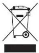
Disposal notes
This symbol on the product, user manual or packaging indicates that this product must not be disposed of with other household waste at the end of its life. It must be handed over to the applicable collection point for the recycling of electrical and electronic equipment.
The materials are recyclable as marked. By recycling, material reusing or other forms of scrap usage you are making an important contribution to environmental protection.
Batteries and accumulators must be removed from the device and disposed of at an appropriate collection point. Please inquire if necessary from the local authority for the appropriate disposal site.
Care and maintenance

Notes on care
The product does not need any maintenance. Always protect it against dust, dirt and moisture.
Clean the product only with a dry cloth (do not use detergent!) lightly rub.
Warranty certificate
GRAUPNER Co., Ltd.
202-809, 18, Bucheon-ro 198beon-gil, Bucheon-si, Gyeonggi-do, Korea. grants from the date of purchase of this product for a period of 24 months. The warranty applies only to the material or operational defects already existing when you purchased the item. Damage due to misuse, wear, overloading, incorrect accessories or improper handling are excluded from the guarantee. The legal rights and claims are not affected by this guarantee. Please check exactly defects before a claim or send the product, because we have to ask you to pay shipping costs if the item is free from defects.
The present construction or user manual is for informational purposes only and may be changed without prior notice. The current version can be found on the Internet at www.graupner.com on the relevant product page. In addition, the company Graupner has no responsibility or liability for any errors or inaccuracies that may appear in construction or operation manuals.
No liability can be accepted for printing errors.
Notes


- MANUAL
- MZ-24 PRO
- INDEX
- USE AND MENU FUNCTIONS....21
- FIRMWARE UPDATE 24
- NOTES ON ENVIRONMENTAL PROTECTION 25
- CARE AND MAINTENANCE....25
- WARRANTY CERTIFICATE....25
- INTRODUCTION
- NOTICE
- SERVICE CENTRE
- GRAUPNER-ZENTRALSERVICE DEUTSCHLAND UG
- SERVICEHOTLINE
- KOREA CENTER
- AMERICAS SERVICE CENTER
- GRAUPNER IM INTERNET
- INTENDED USE
- TARGET GROUP
- PACKAGE CONTENT
- TECHNICAL DATA
- NOTE
- SYMBOLS EXPLICATION
- SAFETY NOTES
- FOR YOUR SAFETY BY HANDLING THE TRANSMITTER
- WARNING
- CAUTION
- FOR YOUR SAFETY BY HANDLING THE BATTERY
- SPECIAL INSTRUCTIONS
- SAFETY NOTES FOR STOCKING BATTERIES
- DESCRIPTION OF THE TRANSMITTER
- CONNECTION ON THE BACK SIDE
- TO INSERT
- TO REMOVE
- DATA RECORDING/DATA SAVING
- CONNECTION SOCKET FOR FLIGHT SIMULATOR OR T/P SYSTEMS
- ATTENTION
- DO NOT USE PLUG-IN CHARGERS BY OTHER MANUFACTURERS OR OTHER CHARGERS
- FIXTURES
- COMMISSIONING
- SETTINGS BY THE FIRST USE
- 1 AND 2 / 9 AND 10
- 4 AND 5 / 7 AND 8
- 3 AND 6
- TRANSMITTER POWER SUPPLY
- BINDING
- EXPLICATIONS ABOUT THE BINDING PROCESS CAN BE FOUND IN THE PART 2 OF THE MANUAL
- CHARGING THE TRANSMITTER BATTERY
- INSERTING THE TRANSMITTER BATTERY
- THROUGH CHARGE SOCKET AND CHARGE WITH AC CHARGER
- POLARITY OF THE MZ CHARGING SOCKET
- USE AND MENU FUNCTIONS
- OPERATION OF THE KEY FIELD
- KEYS LEFT OF THE DISPLAY
- KEYS TO THE LEFT OF THE DISPLAY
- ENTRY LOCK
- DIGITAL TRIM
- DIGITAL TRIM WITH AN OPTICAL AND ACOUSTIC DISPLAY
- DISPLAY
- FIRMWARE UPDATE
- TRANSMITTER SOFTWARE UPDATE
- EG DECLARATION OF CONFORMITY
- S.1006 MZ-24 PRO HOTT
- HERSTELLER / MANUFACTURER
- VERTRIEB DEUTSCHLAND, ÖSTERREICH, EU
- SIMPLIFIED EU DECLARATION OF CONFORMITY
- NOTES ON ENVIRONMENTAL PROTECTION
- DISPOSAL NOTES
- CARE AND MAINTENANCE
- NOTES ON CARE
- WARRANTY CERTIFICATE
- NOTES
Marque : GRAUPNER
Modèle : mz-24 PRO
Catégorie : Jouet radiocommandé