LS-2 - Switcher audio ROLAND - Notice d'utilisation et mode d'emploi gratuit
Retrouvez gratuitement la notice de l'appareil LS-2 ROLAND au format PDF.

| Type de produit | Switch audio avec contrôle de boucle |
| Caractéristiques techniques principales | 2 entrées, 2 sorties, contrôle de niveau, fonction mute, LED d'indication |
| Alimentation électrique | Alimentation secteur 9V DC, adaptateur inclus |
| Dimensions approximatives | 215 mm x 130 mm x 50 mm |
| Poids | 1,2 kg |
| Compatibilités | Compatible avec la plupart des équipements audio et instruments |
| Type de batterie | Non applicable (fonctionne sur secteur) |
| Tension | 9V |
| Puissance | Consommation maximale de 500 mA |
| Fonctions principales | Commutation de signaux audio, contrôle de niveau, fonction mute |
| Entretien et nettoyage | Essuyer avec un chiffon doux, éviter les produits chimiques agressifs |
| Pièces détachées et réparabilité | Réparabilité limitée, pièces disponibles sur demande |
| Sécurité | Ne pas exposer à l'eau, utiliser uniquement l'adaptateur fourni |
| Informations générales utiles | Idéal pour les musiciens et les ingénieurs du son, facile à transporter |
FOIRE AUX QUESTIONS - LS-2 ROLAND
Questions des utilisateurs sur LS-2 ROLAND
0 question sur cet appareil. Repondez a celles que vous connaissez ou posez la votre.
Poser une nouvelle question sur cet appareil
Téléchargez la notice de votre Switcher audio au format PDF gratuitement ! Retrouvez votre notice LS-2 - ROLAND et reprennez votre appareil électronique en main. Sur cette page sont publiés tous les documents nécessaires à l'utilisation de votre appareil LS-2 de la marque ROLAND.
MODE D'EMPLOI LS-2 ROLAND
BOSS LS-2 Line Selector
Instructions
Thank you for purchasing the BOSS LS-2 Line Selector. To make the best use of the unit, please read the instructions carefully.
●The LS-2 provides two separate line-loop outputs.
●The LS-2 features 6 different modes (including effect loop selector and line selector) that enhance its versatility.
●The LS-2 provides individual control over the output level of each line.
●Each line has an indicator, allowing you to easily determine the current state of the unit.
●An AC Adaptor Output Jack is provided to supply power to an external effect unit when an AC adaptor is being used to supply power to the LS-2.
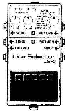
![A—○ B—○ MODE —LEVEL — A+B —○ +20 —○ +20 —○ BYPASS+ [+A+B MIX] OUTPUT SELECT ← SEND — A — RETURN ← ← SEND — B — RETURN ← ← OUTPUT INPUT ← Line Selector® LS-2 DIEOSE](/content/2025/01/131073/images/93d6b6ec8b065caf09514d6f664cd72658dc2a9f85d34ee7aedf91522a326687.jpg)

SPECIFICATIONS
Controls...... Pedal Switch, Mode Selector Switch, Level Control Knobs A/B
Indicators.... Line Indicators A/B (serves also as battery check indicator)
Jacks Input, Output, AC Adaptor In/Out, Send A/B, Return A/B
Input Impedance.... 1 MΩ
Output Impedance.... 1 kΩ
Recommended Load Impedance... 10 kΩ or greater
Residual Noise....-85 dBu or less (IHF-A, Typ.)
Power Supply ...... DC 9 V; Dry battery (6F22/9V), AC Adaptor (PSA-series: Option)
Current Draw 25 mA (DC 9V)
Dimensions 73 (W) x 129 (D) x 59 (H) mm
2-7/8 (W) × 5-1/8 (D) × 2-3/8 (H) inches
Weight 410 g / 14 oz (including battery)
Accessories...... Instructions, Dry Battery; 6F22/9V (Carbon), Rubber Feet x2 (For BCB-6),
Leaflet ("USING THE UNIT SAFELY," "IMPORTANT NOTES," and "Information")
Options ...... AC Adaptor PSA-Series, DC cord PCS-20A
* 0 dBu = 0.775 Vrms
* In the interest of product improvement, the specifications and/or appearance of this unit are subject to change without prior notice.
Copyright © BOSS CORPORATION
All rights reserved. No part of this publication may be reproduced in any form without the written permission of BOSS CORPORATION.
Printed in Taiwan 2003-3-B3-3C 2604781202

BOSS Corporation

BOSS
LS-2
Line Selector
Instructions
•
Thank you for purchasing the BOSS LS-2 Line Selector. To make the best use of the unit, please read the instructions carefully.
●The LS-2 provides two separate line-loop outputs.
●The LS-2 features 6 different modes (including effect loop selector and line selector) that enhance its versatility.
●The LS-2 provides individual control over the output level of each line.
●Each line has an indicator, allowing you to easily determine the current state of the unit.
●An AC Adaptor Output Jack is provided to supply power to an external effect unit when an AC adaptor is being used to supply power to the LS-2.

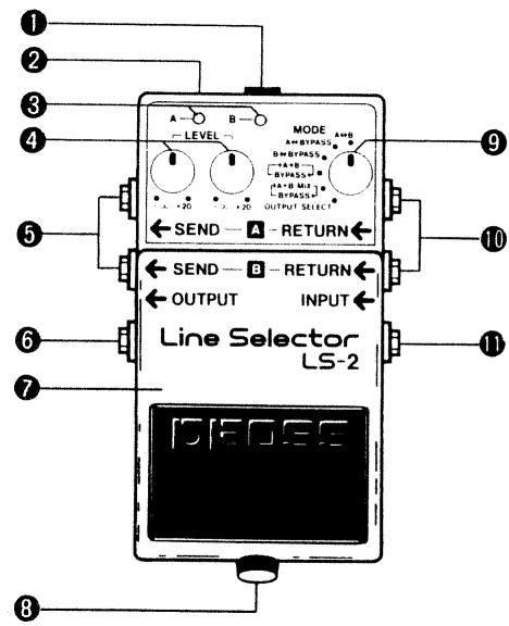
①AC Adaptor In Jack
Connect an AC adaptor ( BOSS PSA-120, 220 or 240 option) to this jack.
*Use of an AC adaptor eliminates the need for battery.
*Be sure to use the specified AC adaptor (PSA-120, 220 or 240). Using any other adaptor may damage the unit.
②AC Adaptor Out Jack
When an AC adaptor is being used to power the LS-2, power can also be supplied to another compact effect unit by connecting a paralleled DC cord (PCS-20A: option) to this jack.
*When you are using battery power, the AC Adaptor Out Jack does not function.
* When using the PSA-120, 220 or 240, be sure that the total current draw of the LS-2 and any external effect unit does not exceed 200mA.
③Line Indicators A/B
The appropriate indicator lights when the corresponding line (A/B) is selected.
* These indicators also serve as a battery check. When they become dim (or do not light at all), replace the battery immediately.
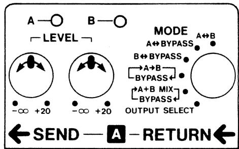
④Level Control Knobs A/B
Each knob controls the output level of the corresponding line (A/B). The output level is variable from - (muted) to +20dB.
* When a knob is set to the center position, the input and output levels are equal.
⑤Send Jacks ( A/B )
These jacks send the signals received by the Input Jack when the corresponding line (A/B) is in use.
⑥Output Jack
Connect an amplifier or other effect unit to this jack.
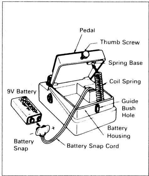
⑦Pedal Switch
This switch selects the line to be used.
⑧Thumb Screw
Loosen this screw to open the pedal for battery replacement. For a detailed explanation, see "Battery Replacement".
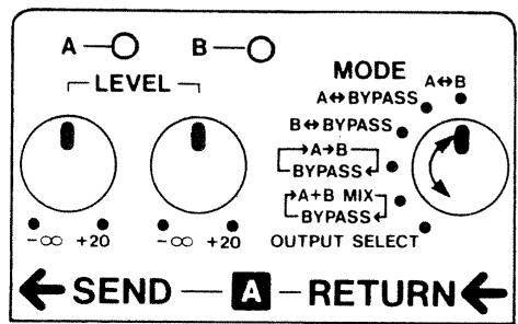
⑨Mode Selector Switch
This switch selects the operating mode. For a detailed explanation, see "MODE DESCRIPTION".
Return Jacks A/B
These jacks feed the signal from the corresponding line ( A/B ) into the unit.
⑪Input Jack
Connect an electric/electronic musical instrument (such as an electric guitar) to this jack.
* Connecting a plug to the Input Jack automatically turns the unit on. Disconnect the plug from the Input Jack when the unit is not in use.
OPERATION
①Select the desired mode.
* Be sure to select an appropriate mode referring to "Mode Description" and "LS-2 Sample Settings".
②Connect the relevant units depending on the mode you have selected.
* Before connecting or disconnecting cords, be sure to turn down the volume on the amplifier.
③Select the desired line by pressing the pedal. Then adjust the output level of each line with the Level Control Knobs.
* The Level Control Knobs may not work depending on how the units are set up.
BATTERY REPLACEMENT
①Loosen the thumb screw on the pedal to open it.
②Take out the battery from the battery housing and disconnect the battery snap.
③Connect a new battery to the battery snap, then replace the battery in to the battery housing.
* Make sure that the polarity of the battery is correct.
④ Push the coil spring into the spring base on the rear of the pedal, then close the pedal.
* Make sure that the snap cord is not caught in the pedal or coil spring.
⑤Insert the thumb screw into the guide bush hole and firmly tighten the screw.
Use one 9-volt battery
IMPORTANT NOTES
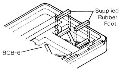
● To place the LS-2 in the BOSS Carrying Box BCB-6, you need to attach the supplied rubber feet to the BCB-6 shown below.
- Remove the battery whenever the unit is not going to be used for an extended period of time.
-
When operating solely on a battery, the unit's indicator becomes dim when the battery is depleted. Replace the battery immediately.
-
If there is a battery in the unit while an AC adaptor is being used, normal operation will continue should the line voltage be interrupted (power blackout) or the power cord become disconnected.
●Should a malfunction occur (or if you suspect there is a problem) discontinue use immediately. Contact qualified service personnel as soon as possible.
natural_image
Three black electronic devices with attached cables, no visible text or symbols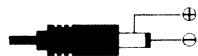
● OUT:9VDC 200mA
The following describes the LS-2's six operation modes:
* When you change modes, be sure to determine the currently selected line using the Line Indicators
A↔B
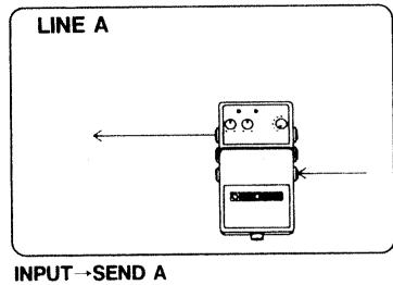
Pressing the pedal alternately selects Line A or Line B. This is an ideal setting for using only the line loop function (when bypass output is not required).
INPUT→SEND A→RETURN A→OUTPUT
flowchart
graph TD
    A["Device 1"] --> B["Device 2"]
    B --> C["Device 3"]
    style A fill:#f9f,stroke:#333
    style B fill:#ccf,stroke:#333
    style C fill:#cfc,stroke:#333
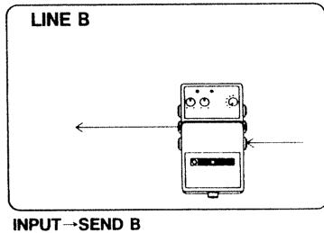
INPUT→SEND B→RETURN B→OUTPUT
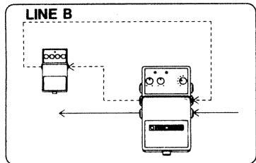
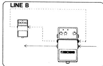
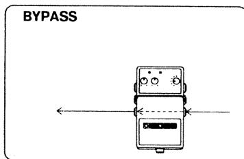
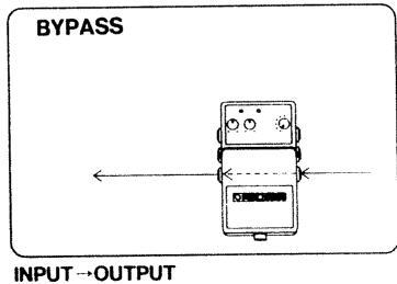
B↔ BYPASS
Pressing the pedal alternately selects Line B or Bypass.
flowchart
graph TD
    A["Device 1"] -->|Arrow to| B["Device 2"]
    B -->|Arrow to| A
    style A fill:#f9f,stroke:#333
    style B fill:#bbf,stroke:#333
INPUT→SEND B→RETURN B→OUTPUT
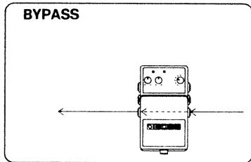
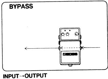
INPUT→OUTPUT
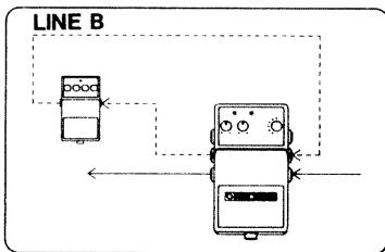
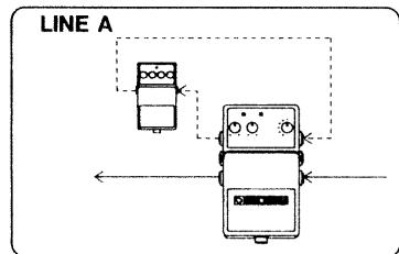
A↔ BYPASS
Pressing the pedal alternately selects Line A or Bypass.

INPUT→SEND A→RETURN A→OUTPUT
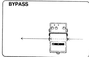
INPUT→OUTPUT
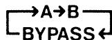
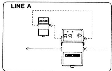
Pressing the pedal repeatedly selects (in sequence) Line A, Line B or Bypass.
INPUT→SEND A→RETURN A→OUTPUT
flowchart
graph TD
    A["Device 1"] --> B["Device 2"]
    B --> C["Line B"]
    C --> D["Output"]
    style A fill:#f9f,stroke:#333
    style B fill:#ccf,stroke:#333
    style C fill:#cfc,stroke:#333
INPUT→SEND B→RETURN B→OUTPUT
INPUT→OUTPUT
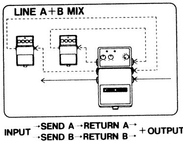
Pressing the pedal alternately selects Line A + Line B (mixed) or Bypass.
flowchart
graph TD
    A["Input"] --> B{SEND A → RETURN A}
    B --> C["Output"]
    D["Input"] --> E{SEND B → RETURN B}
    E --> F["Output"]
    G["Line A + B MIX"] --> H["Control Signals"]
    H --> I["Feedback to Input"]
    style A fill:#f9f,stroke:#333
    style D fill:#f9f,stroke:#333
    style G fill:#f9f,stroke:#333
CE
For EU Countries
This product complies with the requirements of European Directive 89/336/EEC.
OUTPUT SELECT
Pressing the pedal repeatedly selects (in sequence) Send A, Send B or Output.
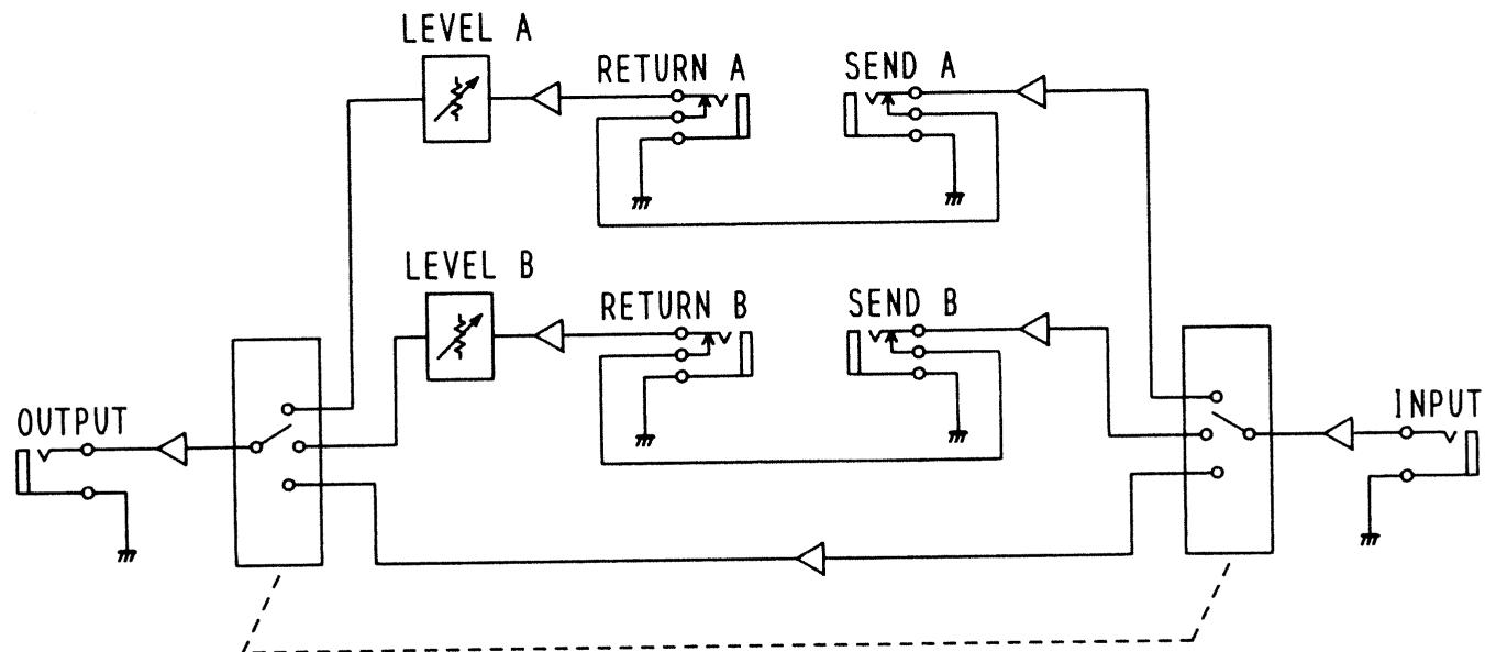
BLOCK DIAGRAM
flowchart
graph TD
    A["OUTPUT"] --> B["Switch"]
    B --> C["LEVEL A"]
    C --> D["RETURN A"]
    D --> E["SEND A"]
    E --> F["LEVEL B"]
    F --> G["RETURN B"]
    G --> H["SEND B"]
    H --> I["INPUT"]
    style A fill:#f9f,stroke:#333
    style F fill:#f9f,stroke:#333
    style I fill:#ccf,stroke:#333
UPC
2604781202
10981