
SA-DX750 - Recepteur TECHNICS - Notice d'utilisation et mode d'emploi gratuit
Retrouvez gratuitement la notice de l'appareil SA-DX750 TECHNICS au format PDF.


| Type de produit | Récepteur stéréo AM/FM |
| Marque | Technics |
| Modèle | SA-DX750 |
| Puissance de sortie | 100 W par canal sous 8 ohms (estimation) |
| Réponse en fréquence | 20 Hz - 20 kHz |
| Distorsion harmonique totale | Inférieure à 0,05 % |
| Rapport signal/bruit | 80 dB |
| Entrées | Phono, CD, Tape, Tuner, Aux |
| Sorties | Enceintes (A/B), Casque, Pré-ampli |
| Dimensions (L x H x P) | 430 x 138 x 350 mm (estimation) |
| Poids | 8,5 kg (estimation) |
| Alimentation | 220-240 V, 50/60 Hz |
| Consommation électrique | 350 W (max) |
| Entretien et nettoyage | Essuyer avec un chiffon sec et doux. Ne pas utiliser de produits chimiques. |
| Sécurité | Ne pas obstruer les fentes de ventilation. Éviter l'humidité. |
| Pièces détachées et réparabilité | Contacter le service après-vente Technics ou un centre agréé. |
FOIRE AUX QUESTIONS - SA-DX750 TECHNICS
Questions des utilisateurs sur SA-DX750 TECHNICS
0 question sur cet appareil. Repondez a celles que vous connaissez ou posez la votre.
Poser une nouvelle question sur cet appareil
Téléchargez la notice de votre Recepteur au format PDF gratuitement ! Retrouvez votre notice SA-DX750 - TECHNICS et reprennez votre appareil électronique en main. Sur cette page sont publiés tous les documents nécessaires à l'utilisation de votre appareil SA-DX750 de la marque TECHNICS.
MODE D'EMPLOI SA-DX750 TECHNICS
Technics®

natural_image
Front view of a retro television receiver with control panel and remote control (no visible text or symbols)AV Control Receiver
Operating Instructions
Model No. SA-DX750

natural_image
Black-and-white illustration of a saxophone with musical notes and a pen, no visible text or symbolsBefore connecting, operating or adjusting this product, please read these instructions completely.
Please keep this manual for future reference.
Dear customer
Thank you for purchasing this product.
For optimum performance and safety, please read these instructions carefully.
Supplied accessories

Please check and identify the supplied accessories.

AC power supply cord (RJA0065-A)....1


AM loop antenna set (RSA0012)....1 (AM loop antenna, antenna holder, screw)
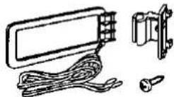

FM indoor antenna (RSA0006)....1


Batteries 2


Remote control (EUR7702020)....1

Refer to the separate booklet, "Remote Control", for remote control operation details.
Use the numbers indicated in parentheses when asking for replacement parts.
(Only for U.S.A.)
To order accessories contact 1-800-332-5368 or web site (http://www.panasonic.com).
User memo:
DATE OF PURCHASE
DEALER NAME
DEALER ADDRESS
TELEPHONE NUMBER
The model number and serial number of this product can be found on either the back or the bottom of the unit.
Please note them in the space provided below and keep for future reference.
MODEL NUMBER
SA-DX750
SERIAL NUMBER
Table of contents
Before use
Listening caution....3
PRECAUTIONS....4
Control reference guide 5
Connections
Connections 6
Connecting video equipment....6
Connecting audio equipment....7
Connecting digital equipment 7
Antenna connections....8
Connecting the AC power supply cord and other information .....9
Speaker connections....10
Placement of speakers....10
Connecting speakers....10
Preparations
Customizing your receiver....12
Basic steps....13
Adjusting speaker output level....14
Operations
DSP sound modes....15
STEREO mode....15
SURROUND mode....15
SFC modes....16
Enjoying the sounds....17
Adjusting the tone and balance 18
Using headphones....18
Muting the volume 19
Adjusting the subwoofer level....19
Using the TAPE MONITOR....19
Radio functions
The radio....20
Manual tuning....20
Preset tuning 21
Reference
Making a recording....22
The HELP function....22
Specifications 23
Maintenance 23
Product Service 23
Troubleshooting guide....24
Servicenter List (U.S.A.) 25
Warranty (U.S.A.) 26
CAUTION
Do not place anything on top of this unit or block the heat radiation vents in any way. In particular, do not place tape decks or CD/DVD players on this unit as heat radiated from it can damage your software.
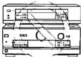
NO

flowchart
graph TD
    A["Enjoying surround sound"] --> B["Pages"]
    B --> C["Connect your equipment"]
    C --> D["6 9"]
    D --> E["Position and connect the speakers"]
    E --> F["10 11"]
    F --> G["Change the settings"]
    G --> H["12 13"]
    H --> I["Adjust speaker output level"]
    I --> J["14"]
    J --> K["Sit back and enjoy the experience"]
    K --> L["17"]
Listening caution


Selecting fine audio equipment such as the unit you've just purchased is only the start of your musical enjoyment. Now it's time to consider how you can maximize the fun and excitement your equipment offers. This manufacturer and the Electronic Industries Association's Consumer Electronics Group want you to get the most out of your equipment by playing it at a safe level. One that lets the sound come through loud and clear without annoying blaring or distortion—and, most importantly, without affecting your sensitive hearing.
We recommend you to avoid prolonged exposure to excessive noise.
Sound can be deceiving. Over time your hearing "comfort level" adapts to higher volumes of sound. So what sounds "normal" can actually be loud and harmful to your hearing.
Guard against this by setting your equipment at a safe level BEFORE your hearing adapts.
To establish a safe level:
- Start your volume control at a low setting.
- Slowly increase the sound until you can hear it comfortably and clearly, and without distortion.
Once you have established a comfortable sound level:
- Set the dial and leave it there.
Taking a minute to do this now will help to prevent hearing damage or loss in the future. After all, we want you listening for a lifetime.
THE FOLLOWING APPLIES ONLY IN THE U.S.A.
CAUTION:
This equipment has been tested and found to comply with the limits for a Class B digital device, pursuant to Part 15 of the FCC Rules.
These limits are designed to provide reasonable protection against harmful interference in a residential installation. This equipment generates, uses and can radiate radio frequency energy and, if not installed and used in accordance with the instructions, may cause harmful interference to radio communications. However, there is no guarantee that interference will not occur in a particular installation. If this equipment does cause harmful interference to radio or television reception, which can be determined by turning the equipment off and on, the user is encouraged to try to correct the interference by one or more of the following measures:
- Reorient or relocate the receiving antenna.
- Increase the separation between the equipment and receiver.
- Connect the equipment into an outlet on a circuit different from that to which the receiver is connected.
- Consult the dealer or an experienced radio/TV technician for help.
Any unauthorized changes or modifications to this equipment would void the user's authority to operate this device.
This device complies with Part 15 of the FCC Rules. Operation is subject to the following two conditions: (1) This device may not cause harmful interference, and (2) this device must accept any interference received, including interference that may cause undesired operation.
WARNING:
TO REDUCE THE RISK OF FIRE, ELECTRIC SHOCK OR PRODUCT DAMAGE, DO NOT EXPOSE THIS APPLIANCE TO RAIN, SPLASHING, DRIPPING OR MOISTURE.
CAUTION:
TO PREVENT ELECTRIC SHOCK MATCH WIDE BLADE OF PLUG TO WIDE SLOT, FULLY INSERT.
CAUTION
RISK OF ELECTRIC SHOCK DO NOT OPEN

CAUTION: TO REDUCE THE RISK OF ELECTRIC
SHOCK, DO NOT REMOVE SCREWS.
NO USER-SERVICEABLE PARTS
INSIDE
REFER SERVICING TO QUALIFIED
SERVICE PERSONNEL.

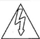
The lightning flash with arrowhead symbol, within an equilateral triangle, is intended to alert the user to the presence of uninsulated "dangerous voltage" within the product's enclosure that may be of sufficient magnitude to constitute a risk of electric shock to persons.
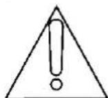
The exclamation point within an equilateral triangle is intended to alert the user to the presence of important operating and maintenance (servicing) instructions in the literature accompanying the appliance.

PRECAUTIONS
Before using this unit please read these operating instructions carefully. Take special care to follow the warnings indicated on the unit itself as well as the safety suggestions listed below. Afterwards keep them handy for future reference.
Safety
- Power Source — The unit should be connected to power supply only of the type described in the operating instructions or as marked on the unit.
- Polarization — If the unit is equipped with a polarized AC power plug (a plug having one blade wider than the other), that plug will fit into the AC outlet only one way. This is a safety feature. If you are unable to insert the plug fully into the outlet, try reversing the plug. If the plug should still fail to fit, contact your electrician to replace your obsolete outlet. Do not defeat the safety purpose of the polarized plug.
- Power Cord Protection — AC power supply cords should be routed so that they are not likely to be walked on or pinched by items placed upon or against them. Never take hold of the plug or cord if your hand is wet, and always grasp the plug body when connecting or disconnecting it.
- Nonuse Periods — When the unit is not used, turn the power off. When left unused for a long period of time, the unit should be unplugged from the household AC outlet.
Installation
Environment
- Outdoor Antenna Grounding — If an outside antenna is connected to the receiver, be sure the antenna system is grounded so as to provide some protection against voltage surges and built-up static charges. Section 810 of the National Electrical Code, ANSI/NFPA No. 70-1990, provides information with respect to proper grounding of the mast and supporting structure, grounding of the lead-in wire to an antenna discharge unit, size of grounding conductors, location of antenna-discharge unit, connection to grounding electrodes, and requirements for the grounding electrode. See figure below.

NEC—NATIONAL ELECTRICAL CODE
- Water and Moisture — Do not use this unit near water-for example, near a bathtub, washbowl, swimming pool, or the like. Damp basements should also be avoided.
- Heat — The unit should be situated away from heat sources such as radiators and the like.
It also should not be placed in temperatures less than 5°C (41°F) or greater than 35°C (95°F).
Placement
- Ventilation — The unit should be situated so that its location or position does not interfere with its proper ventilation. Allow 10 cm (4") clearance from the rear of the unit.
- Foreign Material — Care should be taken so that objects do not fall into and liquids are not spilled into the unit. Do not subject this unit to excessive smoke, dust, mechanical vibration, or shock.
- Magnetism — The unit should be situated away from equipment or devices that generate strong magnetic fields.
- Stacking — Do not place heavy objects, other than system components, on top of the unit.
- Surface — Place the unit on a flat, level surface.
- Carts and Stands — The unit should be used only with a cart or
stand that is recommended by the manufacturer. The unit and cart combination should be moved with care. Quick stops, excessive force, and uneven surfaces may cause the unit and cart combination to overturn. - Wall or Ceiling Mounting — The unit should not be mounted to a wall or ceiling, unless specified in this operating instructions.

Maintenance
Clean the cabinet, panel and controls with a soft cloth lightly moistened with mild detergent solution.
Do not use any type of abrasive pad, scouring powder or solvent such as alcohol or benzine.
Service
- Damage Requiring Service — The unit should be serviced by qualified service personnel when:
(a) The AC power supply cord or the plug has been damaged; or
(b) Objects have fallen or liquid has been spilled into the unit; or
(c) The unit has been exposed to rain; or
(d) The unit does not appear to operate normally or exhibits a marked change in performance; or
(e) The unit has been dropped, or the enclosure damaged. - Servicing — The user should not attempt to service the unit beyond that described in the operating instructions. All other servicing should be referred to an authorized service personnel.
For the address of an authorized servicenter:
In the U.S.A., call 1-800-211-7262 or visit www.panasonic.com In Canada, call 905-624-5505 or visit www.panasonic.ca
Control reference guide

Reference pages are given in parentheses.
Main unit
① Standby/on button [POWER, ©/I] ......(13)
Press to switch the unit from on to standby mode or vice versa. In standby mode, the unit is still consuming a small amount of power.
② Speaker on/off button [SPEAKERS]....(14, 17)
③ Help/reset button [-HELP/-RESET]....(22)
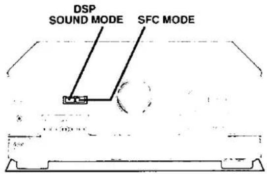
④ DSP sound mode select button [DSP SOUND MODE]....(13, 17)
⑤ SFC mode select button [SFC MODE]....(13, 17)
⑥ Memory button [MEMORY]....(21)
⑦ Volume control [VOLUME] .....(17)
⑧ Input selector [INPUT SELECTOR]....(13, 17)
⑨ Digital input select button/indicator [DIGITAL INPUT].....(17)
⑩ Subwoofer level button [SUBWOOFER LEVEL]....(19)
⑪ Headphone jack [PHONES]....(18)
⑫ Tuning buttons [TUNING, ∨, ∧]....(20)
⑬ Preset channel button [PRESET]....(21)
⑭ Band select button [BAND]....(20)
⑮ FM mode select button [FM MODE]....(20)
⑯ Display section
⑰ Tape monitor button [TAPE MONITOR]....(19)
⑯ Tone and balance select button [BASS/TREBLE, BALANCE]....(18)
⑲ Tape monitor indicator .....(19)
② Tone and balance adjust buttons [-, +, L, R]....(18)
Display section
② Display
② Frequency unit indicators [kHz, MHz]....(20)
② Program format indicators [L, C, R, LS, S, LFE, RS].....(17)
②4 Front speaker indicator [-SPEAKERS-]....(17)
② Stereo indicator [STEREO]....(20)
② Monaural indicator [MONO]....(20)
⑳ Memory indicator [M] ......(21)
② Tuned indicator [TUNED]....(20)
29 Signal format indicators
[FIXED, PCM, ☐ DIGITAL, ☐ PRO LOGIC]......(17)
③ DSP sound mode indicators
[-SOUND MODE-, SFC, STEREO, SURROUND]......(17)
Refer to the separate booklet, "Remote Control", for a guide to the remote control's buttons.
Connections
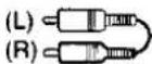
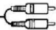
Stereo connection cable
White
Red
Video connection cable

To connect equipment, refer to the appropriate operating instructions.
Peripheral equipment and cables sold separately unless otherwise indicated.
Note
- Turn off all components before making any connections.
- Use digital connection to enjoy Dolby Digital (→ page 17).
- Use analog connection to enjoy sources that cannot be decoded on this unit and to record a source (⇒ pages 15 and 22).
Connecting video equipment

flowchart
graph TD
    A["TV or monitor"] -->|VIDEO IN| B["TV monitor"]
    A -->|VIDEO OUT| C["TV monitor"]
    A -->|AUDIO OUT| D["TV monitor"]
    B -->|VCR| E["TV monitor"]
    C -->|VCR| F["TV monitor"]
    D -->|VCR| G["TV monitor"]
    E --> H["DVD player"]
    F --> H
    G --> H
    H --> I["VIDEO OUT"]
    H --> J["VIDEO OUT"]
    H --> K["VIDEO OUT"]
    H --> L["VIDEO OUT"]
    H --> M["VIDEO OUT"]
    H --> N["VIDEO OUT"]
    H --> O["VIDEO OUT"]
    H --> P["VIDEO OUT"]

Connecting audio equipment
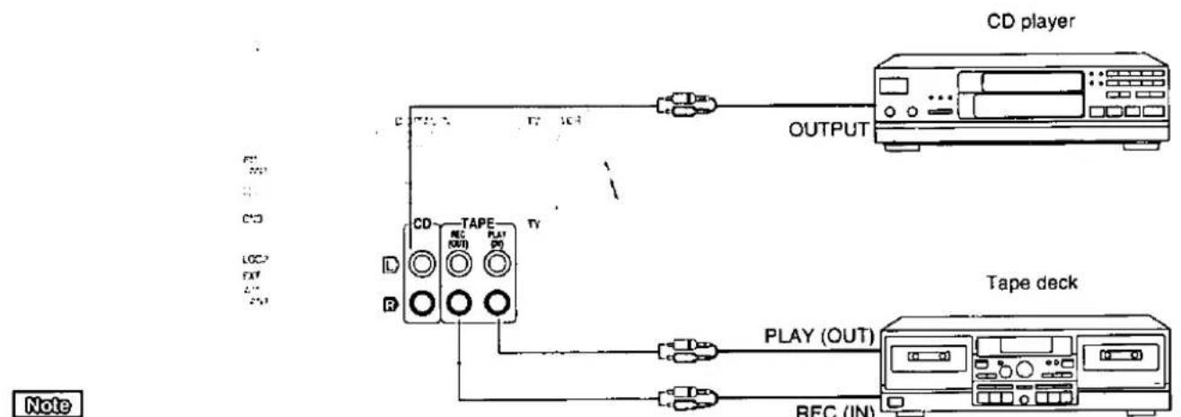
flowchart
graph TD
    A["CD player"] -->|OUTPUT| B["Tape deck"]
    B -->|PLAY (OUT)| C["RECK/DVD"]
    B -->|PLAY (OUT)| D["RECK/DVD"]
    B -->|PLAY (OUT)| E["RECK/DVD"]
    style A fill:#f9f,stroke:#333
    style B fill:#ccf,stroke:#333
    style C fill:#cfc,stroke:#333
    style D fill:#fcc,stroke:#333
    style E fill:#cff,stroke:#333
If you have a graphic equalizer, connect it to the TAPE terminals ( page 19).
Connecting digital equipment

flowchart
graph TD
    A["Satellite receiver, etc."] --> B["DIGITAL OUT"]
    B --> C["Digital IN"]
    C --> D["OPTICAL1 OPTICAL2 COAXIAL (TV)"]
    C --> E["TAPC"]
    D --> F["CD player"]
    E --> G["DVD player"]
    F --> H["Digital OUT"]
    G --> I["Digital OUT"]
    J["Optical fiber cable connection"] --> K["Dust cap"]
    K --> L["Do not bend the optical fiber cable."]
    K --> M["If the digital optical connector is not going to be used, be sure to attach the dust cap to prevent exposure to dust."]
    N["Note"] --> O["This unit cannot decode Dolby Digital RF (radio frequency) signals from a laser disc player."]
    P["Changing the digital input settings"] --> Q["You can change the input settings for the digital terminals if necessary (for example, if your CD player doesn't have a coaxial output terminal). Note the equipment you have connected to the terminals, then change the settings (⇒ pages 12–13)."]
Antenna connections

flowchart
graph TD
    A["FM indoor antenna (included)"] --> B["Adhesive tape"]
    B --> C["FM ANT 75Ω"]
    C --> D["AM ANT"]
    D --> E["AM loop antenna (included)"]
    E --> F["When mounting the antenna to a column, wall or rack"]
    F --> G["Screw (included)"]
    G --> H["AM loop antenna"]
    H --> I["● Fit the AM loop antenna holder (included) onto the rear panel of this unit and then attach the AM loop antenna to it (facing in the direction of best reception)."]
    H --> J["● Keep the antenna cord away from tape decks, DVD players, and other cords."]
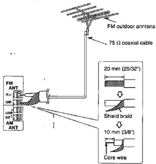
To connect an outdoor antenna
FM outdoor antenna
- Disconnect the FM indoor antenna.
- The antenna should be installed by a competent technician.
- Twist the coaxial cable's shield braid firmly and connect it to the GND terminal.
AM outdoor antenna
- Run a piece of vinyl wire horizontally across a window or other convenient location.
- Leave the loop antenna connected.
- Disconnect the antenna when the unit is not in use. Do not use the antenna during an electrical storm.

Connecting the AC power supply cord and other information
"SWITCHED" AC outlet
Power to the outlet is controlled by the power switch of this unit. Audio equipment rated up to a maximum of 80 W can be connected here. If equipment exceeding this rating is connected, the outlet may be rendered inoperable. Consult your dealer to replace the fuse.


flowchart
graph TD
    A["AC IN ~"] --> B["Ground"]
    C["AC OUTLET"] --> D["Ground"]
    D --> E["Power Supply"]
    E --> F["Ground"]
AC power supply cord (included)
Connect this cord after all other cables and cords are connected.
Household AC outlet (AC 120 V/60 Hz)
Note
The included AC power supply cord is for use with this unit only. Do not use it with other equipment.
Conserving power
The unit consumes 1 W even when it is turned off with [POWER, d/l]. To save power when the unit is not to be used for a long time, unplug it from the household AC outlet. If the unit is left unplugged for longer than a few weeks, all settings will revert to the factory settings. Do the settings again if this occurs.

Placement of speakers

Front speakers
Place on the left and right of the TV at seated ear height so that there is good coherency between the picture and sound.
Center speaker
Place underneath or above the center of the TV. Aim the speaker at the seating area.
Surround speakers
Place on the side of or slightly behind the seating area, about one meter higher than ear level.
Subwoofer
The subwoofer can be placed in any position as long as it is at a reasonable distance from the TV.
Note that some experimentation can yield the smoothest low frequency performance. Placement near a corner can increase the apparent output level, but can result in unnatural bass.
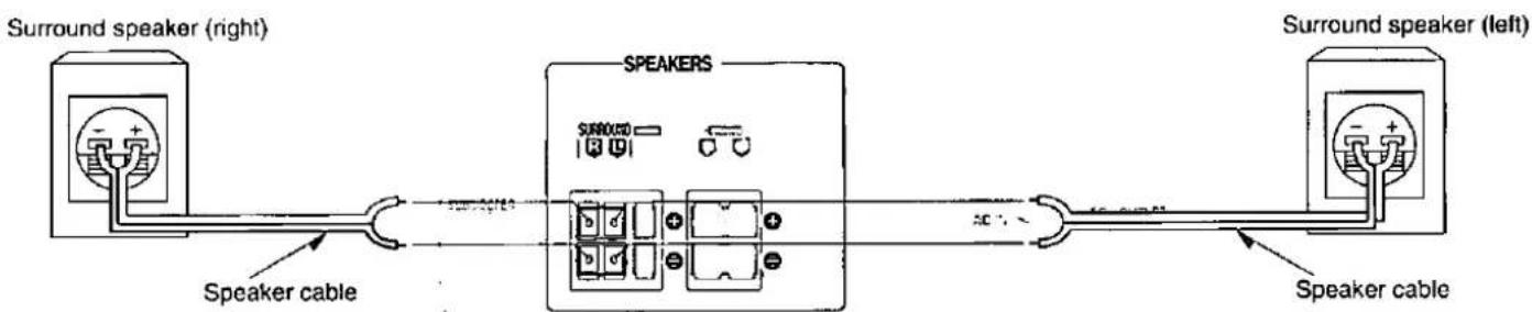
Connecting speakers
Other connections are possible depending on your speaker system.
See your speaker system's operating instructions for details.
Front speakers

Center speaker
Speaker impedance: 6-8 Ω

Surround speakers
Speaker impedance: 6-8 Ω
Subwoofer

This receiver does not have an amplifier for the subwoofer.
To connect a passive subwoofer
- Connect another amplifier and connect the subwoofer to it.
Or
- Connect a passive subwoofer that has front speaker terminals
(See the operating instructions of the speaker system for details.)

Customizing your receiver
Change the settings to suit your speakers and equipment and to suit the environment in which the unit is to be used. Before making any changes, read the following descriptions, note the factory settings and ranges, and refer to the instructions for the speakers and equipment.
The settings remain intact until they are changed, even after the power is turned off.
Setting descriptions
SIZE
Change to suit the speakers you have connected.
LARGE: For speakers that can reproduce a full sound range, particularly the bass range below 100 Hz.
SMALL: For speakers that cannot adequately reproduce the bass range. This setting is sufficient for most speakers if you are using a subwoofer.
NONE: For speakers you haven't connected (center or surround).
The factory settings are: Front: LARGE Center and surround: SMALL
For the subwoofer, select YES if you have connected one (lfactory setting), or NO if you have not.
DISTANCE
Enter the distance of the speakers from the seating position so that the sound from all the speakers (except for the subwoofer) reaches you at the same time.
You can select distances between 3 and 30 feet at one-foot intervals.
The factory settings are: Front and center: 10 FEET Surround: 5 FEET
FILTER
This setting allows you to change the cut-off for bass output from the front speakers. If you set the front speakers to "SMALL", the filter is set to 100 Hz. Raise the cut-off if the bass from the front speakers is unsatisfactory so that this bass is output through the subwoofer.
You can raise the cut-off from 100 Hz to either 150 Hz or 200 Hz.
DR COMP - Dynamic range compression
Change this setting to listen to software at low volume (such as late at night) and maintain audio clarity. This setting works with Dolby Digital software. It reduces the peak level in loud scenes without affecting the sound field.
OFF: The software is played with the original dynamic range (factory setting).
STANDARD: The level recommended by the producer of the software for household viewing.
MAX: The maximum allowable compression (recommended for night viewing).
D-INPUT - Digital input
Change these settings to suit the connections you have made to the three digital input terminals, COAX, OPT1, and OPT2 ( page 7), so that the correct source is selected when you turn [INPUT SELECTOR] ( page 17).
The factory settings are: CD: COAX
DVD: OPT2
TV: OPT1
DIMMER
This setting allows you to dim the unit's display for better viewing in a darkened room.
The factory setting is OFF (normal brightness).
1
2


3


4
SIZE, DISTANCE, D-INPUT
INPUT SELECTOR
FILTER, DR COMP, DIMMER
INPUT SELECTOR

5

Customizing your receiver
Basic steps
If you allow about 10 seconds to elapse between settings, the procedure is canceled, all settings are returned to how they were, and the previous display is restored. Begin again if this occurs.
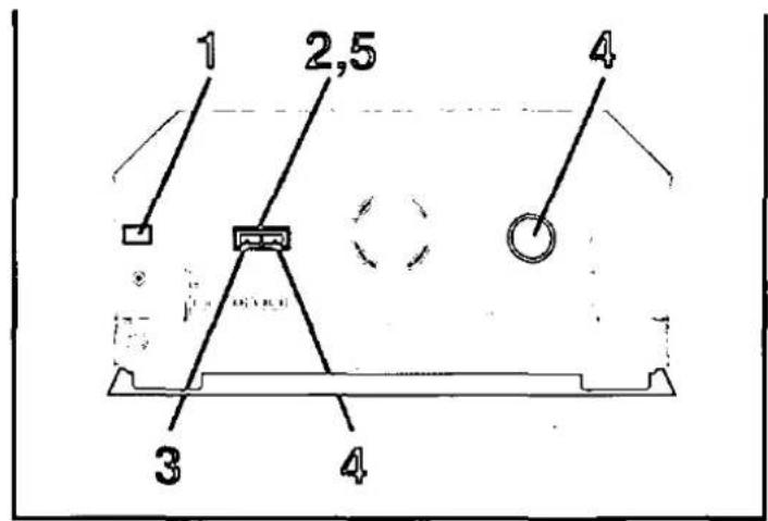
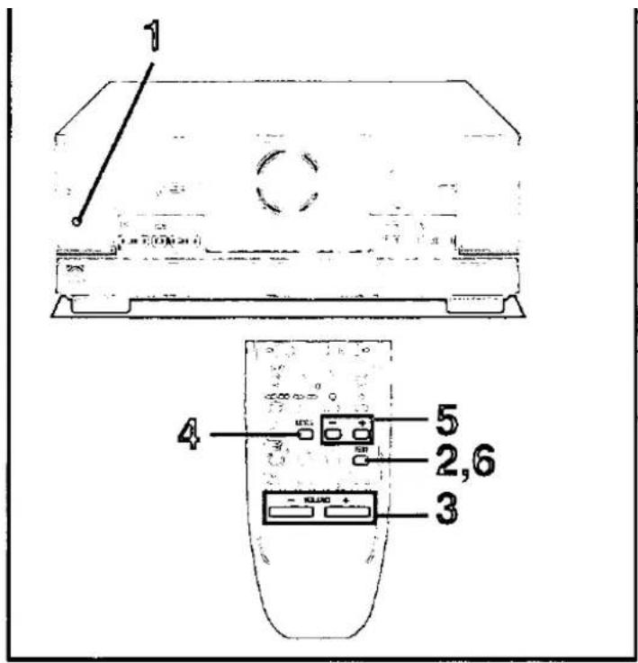
1 Press [POWER, ⏻/l].
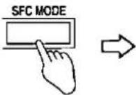
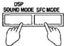
2 Press [DSP SOUND MODE] and [SFC MODE] at the same time.
3 Press [DSP SOUND MODE] to select the item you want to change.
Each time you press the button:
SIZE--DISTANCE--FILTER--DR COMP--D-INPUT--DIMMER
The image contains no text. The horizontal line is a stylistic or background element and must be ignored according to the rules.
4 Change the settings ( below).
Repeat steps 3 and 4 to complete the necessary settings.
5 Press [DSP SOUND MODE] and [SFC MODE] at the same time.
Changing the settings
SIZE
① Press [SFC MODE] to select the speaker you want to set.
Each time you press the button:
FRONT → CENTER → SURROUND → SUB-WFR (Subwoofer)
1
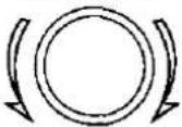
② Turn [INPUT SELECTOR] to change the setting.
When you turn the selector:
FRONT: SMALL ↔ LARGE
CENTER and SURROUND: NONE ↔ SMALL ↔ LARGE
SUB-WFR: NO ↔ YES
③ Repeat ① and ② to change other SIZE settings.
DISTANCE
① Press [SFC MODE] to select the speaker you want to set.
Each time you press the button:
FRONT → CENTER → SURROUND
[Figure]
② Turn [INPUT SELECTOR] to set the distance.
③ Repeat ① and ② to change other DISTANCE settings.
FILTER
Turn [INPUT SELECTOR] to set the cut-off.
When you turn the selector:
100 150 200
DR COMP
Turn [INPUT SELECTOR] to change the setting.
When you turn the selector:
OFF STANDARD MAX
D-INPUT
① Press [SFC MODE] to select the input position you want to set.
Each time you press the button:
CD COAX → DVD OPT2 → TV OPT1
↑
These are the factory settings. Actual displays depend on the changes you make. If you change one setting, the other corresponding setting will also change.
② Turn [INPUT SELECTOR] to change the setting.
When you turn the selector:
COAX OPT1 OPT2
↑
③ Repeat ① and ② to change other D-INPUT settings.
DIMMER
Turn [INPUT SELECTOR] to change the setting.
When you turn the selector:
OFF←→ON


Adjusting speaker output level
Adjust the level of the speakers so they are the same apparent level as the front speakers when you are sitting where you would normally enjoy a source.
1 Press [SPEAKERS] to turn on SPEAKERS.
2 Press [TEST] to output the test signal.
DSP sound mode switches to SURROUND mode.
The signal is output from each speaker in order for about two seconds each:
L: Front speaker (left)
C: Center speaker
R: Front speaker (right)
RS: Surround speaker (right)
LS: Surround speaker (left)
SW: Subwoofer
Speakers set as "NONE" or "NO" are skipped.
Note
The test signal will not be output if DSP is defeated ( page 20).
3 Adjust the volume to the level normally used.
Adjust the balance of the front speakers if necessary ( page 18).
4 Press [LEVEL] to select the speaker channel to adjust.
The current level appears on the display.
Press again to change the speaker channel.
Speakers set as "NONE" or "NO" are skipped.
5 Press [-] or [+] to adjust the level to the same apparent level as the front speakers.
C, RS, and LS can be adjusted between -10 dB and +10 dB, with zero being the current level of the front speakers.
SW can be set to MIN, between 1 to 19, or MAX.
Repeat steps 4 and 5 for each speaker channel.
6 Press [TEST] to stop the test signal.
For your reference
Subwoofer output is easily influenced by the source played. You can achieve better results by adjusting its output while listening to a source ( page 19).

A
B
©

flowchart
graph TD
    A["Digital Input"] --> B["Digital Display"]
    B --> C["Fixed PCM Output"]
DSP sound modes
The digital sound processor (DSP) in this unit can decode Dolby Digital signals. It automatically determines the type of signal, PCM or Dolby Digital, and processes it accordingly.
The DSP can add surround-like effects to stereo sources (analog or PCM signals).
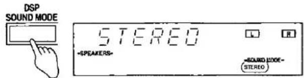
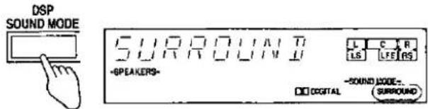
Choose from the STEREO, SURROUND, or SFC modes.
The DSP may interfere with radio reception. You can turn it off if this occurs ( page 20).
Output is in stereo when you turn the DSP off so sound is only heard through the front speakers.
Note
- PCM with a sampling frequency of 44.1 kHz is the digital signal format normally found on CDs. Some DVDs also use this format but often with a higher sampling rate.
- This unit cannot process other digital signal formats, such as DTS, PCM signals with sampling frequencies of 96 kHz and 192 kHz, and MPEG.
A STEREO mode
Use this mode to play digital or analog stereo sources or to play surround sources through two speakers. When surround sources are played in this mode, the sounds intended for the other speaker channels are played through the front speakers.
B SURROUND mode
Select this mode when you are playing a Dolby Digital surround source or an analog source that is recorded with Dolby Surround (VCR, for example).

Changing the recognition mode
In rare cases, the unit may have trouble recognizing the digital signals on discs. With the PCM signals on CDs, this may cause the beginning of a track to be cut off. Engage the PCM FIX mode if this occurs.
This mode does not need to be changed under normal circumstances. Change it only if the unit appears to be having trouble recognizing the software you are playing.
While the input source is selected and digital input is engaged:
Press and hold [DIGITAL INPUT].
The current mode is displayed. Press again to change the mode.
Each time you press the button:
AUTO PCM FIX
When the PCM FIX mode is on, the unit cannot process other signals. This may cause noise to be output. Select "AUTO" if this occurs.
The selected mode is stored even if the unit is turned off.
A

![TECHNICS SA-DX750 - Press and hold [DIGITAL INPUT]. - 3](/content/2026/06/1310556/images/1ac5041740e20371376260bc1cb96ec1590bf8971058b93074b77c73a449851c.jpg)
flowchart
graph TD
    A["HALL"] --> B["CLUB"]
    A --> C["LIVE"]
    A --> D["THEATER"]
    A --> E["SIM SURR"]
    F["-SPEAKERS-"] --> A
    G["-ROUND CODE=5FC"] --> A
B

DSP sound modes
A SFC modes
Enjoy an enhanced sound experience with greater presence and spread by using these SFC (sound field control) modes with PCM or analog stereo sources.
The SFC modes cannot be used if the input signal is Dolby Digital.
Choose from the following modes.
HALL
Imparts the reflection and spread of a large concert hall.
CLUB
Conveys the exciting and intimate atmosphere of a jazz club.
LIVE
Brings you up close for "live" stage performance and smoother vocals.
THEATER
Recreates natural sound ambience and direction.
SIM SURR (Simulated Surround)
Heightens the sensation of expanded space with stereo sources, and augments monaural sources.
B Adjusting the sound field
You can adjust the sound field by adjusting the level of the speakers and the delay time of the surround speakers. These adjustments can be made for each SFC mode.
To adjust the speaker level
① Press [LEVEL] to select the speaker channel.
Each time you press the button:
C→RS→LS→SW

Speakers set as "NONE" or "NO" are skipped.
② Press [-] or [+] to adjust the level.
C, RS, and LS:
-10 dB to +10 dB
SW:
--- (off) --> MIN --> 1-19 --> MAX
To adjust the delay time
① Press [DELAY].
② Press [-] or [+] to change the delay time.
Delay time can be set at 10-millisecond (ms) intervals between 10 and 100 ms.
The factory setting is 50 ms for each mode.
1

2
SPEAKERS
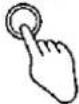

3
INPUT SELECTOR
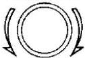
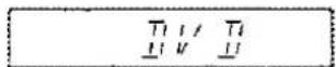
4
①

②

![SURROUND *SPEAKERS- [SIGNATURES] [SIGNATURES] [SIGNATURES] [SIGNATURES] [SIGNATURES] [SIGNATURES] [SIGNATURES] [SIGNATURES] [SIGNATURES] [SIGNATURES] [SIGNATURES] [SIGNATURES] [SIGNATURES] [SIGNATURES] [SIGNATURES] [SIGNATURES] [SIGNATURES] [SIGNATURES] [SIGNATURES] [SIGNATURES] [SIGNATURES]](/content/2026/06/1310556/images/df2d8db6a4f7b5416a7f29ba738470c536c9477642e7625dbc6ae96849ae3c95.jpg)
6

Enjoying the sounds
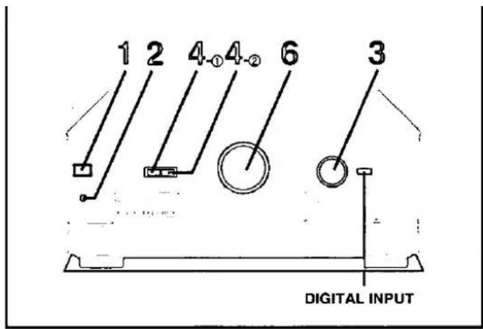
1 Press [POWER, /l ].
2 Press [SPEAKERS] to turn on SPEAKERS.
3 Turn [INPUT SELECTOR] to select the input source.
To switch between analog and digital input (CD, DVD, and TV)
Press [DIGITAL INPUT].
Each time you press the button:
ANALOG ↔ DIGITAL
The indicator lights when you select "DIGITAL".
Once you have set the mode for a source, that mode is engaged whenever you select that source.
4 Select the DSP sound mode.
① Press [DSP SOUND MODE].
The indicator corresponding to the mode lights.
Select the mode appropriate to the source ( pages 15–16).
② When you select "SFC"
Press [SFC MODE].
Once you have set the mode for a source, that mode is engaged whenever you select that source.
5 Start playing the source.
Refer to the equipment's instructions for details.
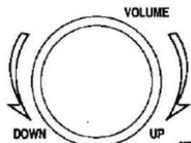
6 Adjust the volume.
When you finish listening
Be sure to reduce the volume and press [POWER, C/I] to switch the unit to standby.
For your reference
- If you are using a VCR and you select TAPE, CD or TUNER The picture will remain on the screen.
- The signal format indicators
The following indicators light depending on the source you are playing.
□□ DIGITAL
Dolby Digital Sources
PRO LOGIC
Analog sources in SURROUND mode
Digital sources with PCM signals in SURROUND mode
Dolby Digital sources that contain Dolby Pro Logic in SURROUND mode
- The program format indicators (L, C, R, LS, S, LFE, RS)
The program format indicators light up to indicate the channels contained in the digital input signal. They do not light when input is analog.
L: Front channel (left)
C: Center channel
R: Front channel (right)
LS: Surround channel (left)
RS: Surround channel (right)
S: If the surround channel is monaural.
LFE (Low Frequency Effect): Deep-bass effect.

1

2
BASS, TREBLE

B
Enjoying the sounds
A Adjusting the tone and balance
You can adjust the tone (BASS and TREBLE) only when the DSP sound mode is STEREO and input is either analog or PCM. You cannot adjust the tone while the DSP is defeated.
1
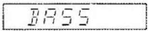
Press [BASS/TREBLE, BALANCE].
Each time you press the button:
BASS → TREBLE → BALANCE
![TECHNICS SA-DX750 - Press [BASS/TREBLE, BALANCE]. - 1](/content/2026/06/1310556/images/de987c212a2e5b19bd938a47fa18cadcc98612109e2836e6ce3924e1f53b4ea5.jpg)
BASS: To adjust the bass
TREBLE: To adjust the treble
BALANCE: To adjust the left/right sound balance
2
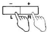
Press [-, L] or [+, R] .
-, L: to lower the selected tone or shift the balance to the left speaker.
+, R: to raise the selected tone or shift the balance to the right speaker.
The previous display returns after a few seconds.
B
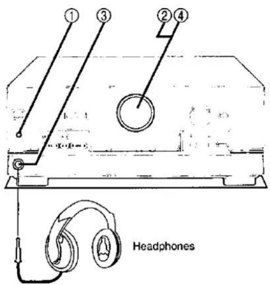
Using headphones
① Press [SPEAKERS] to turn off the speakers.
Turning the speakers off automatically engages STEREO mode and ensures no sound is heard from the subwoofer.
(Sound will seem unusual if you use another DSP mode.)
② Reduce the volume.
③ Connect the headphones (not included).
Plug type: 6.3 mm (1/4") stereo
④ Adjust the volume.
Note
Avoid listening for prolonged periods of time to prevent hearing damage.
A
MUTING


B
SUBWOOFER LEVEL


©
TAPE MONITOR

Enjoying the sounds
A Muting the volume
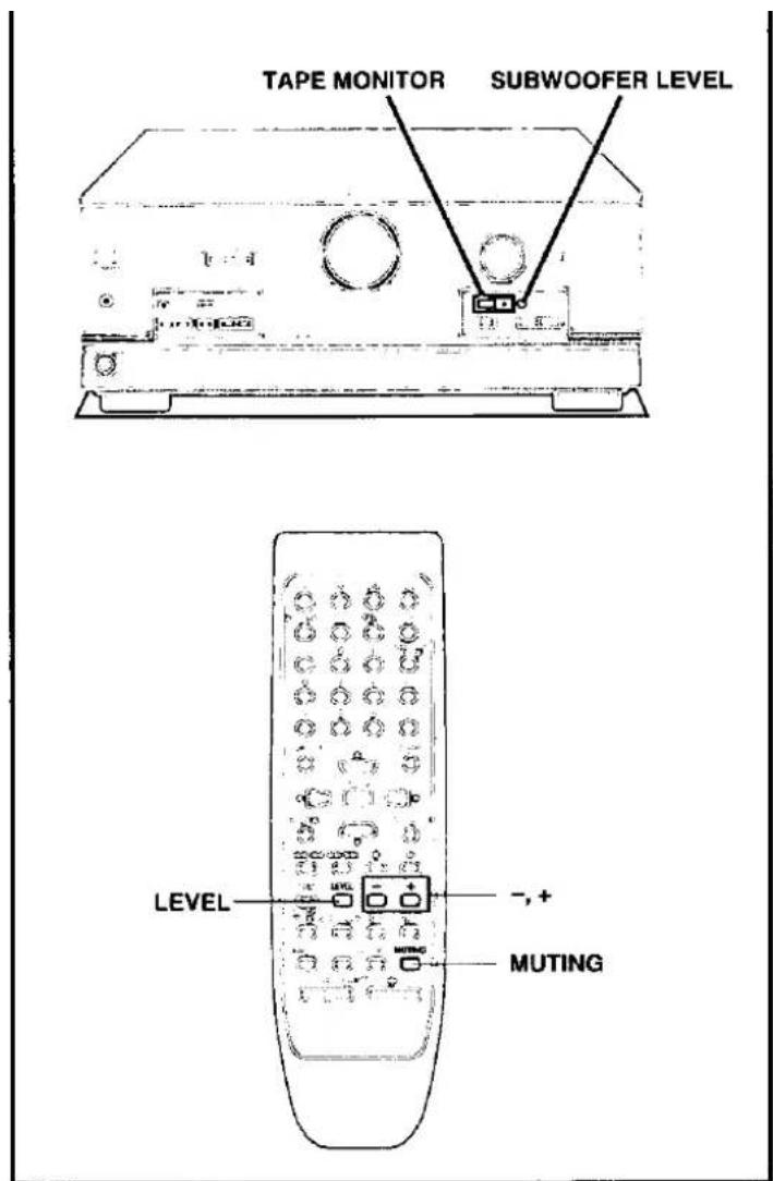
Press [MUTING].
The message "MUTING ON NOW" runs repeatedly from right to left across the display as long as the muting function is on.
To cancel
Press [MUTING].
Muting is also canceled when the unit is turned off.
B Adjusting the subwoofer level
You can adjust the volume of the subwoofer while listening to a source. No sound is heard from the subwoofer if "SW ---" is selected. This setting can be done for each DSP mode.
You cannot adjust the subwoofer level while the DSP is defeated.
The factory setting is "SW 10".
Press [SUBWOOFER LEVEL].
The current setting is shown.
Each time you press the button:
SW --- → SW MIN → SW 5 → SW 10 → SW 15 → SW MAX
To make finer adjustments
① Press [LEVEL] to select "SW".
② Press [-] or [+].
Note
Sound from the subwoofer can be distorted if you raise the unit's volume while subwoofer level is high. Reduce subwoofer level if this occurs.
C Using the TAPE MONITOR
Use the tape monitor if you have connected a graphic equalizer to the TAPE terminals.
Press [TAPE MONITOR].
The "TAPE MONITOR" indicator lights and the tape monitor comes on.
Sources other than tape can still be selected with [INPUT SELECTOR] while the "TAPE MONITOR" indicator is on.
Press [TAPE MONITOR] again to turn the tape monitor off.
(→ See "Making a recording" on page 22 for details on how to use the tape monitor during recording.)
Note
- The tape monitor cannot be used when input is digital and turns off if you select digital input.
- Depending on the setting, the graphic equalizer can cause distortion.

1
INPUT SELECTOR

2


3


B

The radio
A Manual tuning
You can tune radio stations manually by selecting the station's frequency, or you can preset up to 30 stations into channels to make tuning simpler (⇒ page 21).
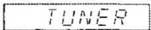
1 Turn [INPUT SELECTOR] to select "TUNER".
2 Press [BAND] to select "FM" or "AM".
3 Press [TUNING ∨ or ∧] to select the frequency of the station.
Tuning intervals: FM - 0.2 MHz
AM - 10 kHz
"TUNED" lights when tuned.
"STEREO" lights during FM stereo broadcasts.
Automatic tuning
Hold down [TUNING ∨ or ∧] until the frequency begins to scroll. Tuning stops when a station is found. (Tuning may stop if there is interference.)
Improving reception
FM mode
You can improve FM reception by switching reception to monaural. Press [FM MODE].
"MONO" lights.
Press [FM MODE] again to cancel.
DSP DEFEAT
You can improve reception by turning off the DSP ( page 15). Press and hold [DSP SOUND MODE] until "DEFEAT" appears. Press and hold [DSP SOUND MODE] again to turn the DSP on.
For your reference
DVD players can interfere with radio reception. Turn the DVD player off or move it further away from the antennas if this occurs.
B Direct tuning
①Press [TUNER/BAND].
The band changes each time you press the button.
②Press [DIRECT TUNING/DISC ENTER].
③Press the numbered buttons to enter the frequency.
e.g. To select 107.9 MHz, press [1] → [0] → [7] → [9]
Tuning intervals: FM - 0.1 MHz
AM - 10 kHz
Note
- If you do not press a button while the cursor is flashing, the display returns to the frequency being received.
- If the frequency has not been input correctly, "ERROR" will be displayed.



The radio
Preset tuning
Choose either automatic presetting, which presets the stations the tuner can receive, or manual presetting, which allows you to select the stations to preset and the order in which they are to be preset. There are 30 channels available for presetting.
Remember
If a new station is preset into a channel, the old station is erased.
A Automatic presetting
Presetting FM stations
Preparation: Tune to the FM frequency where you want to begin presetting ( page 20).
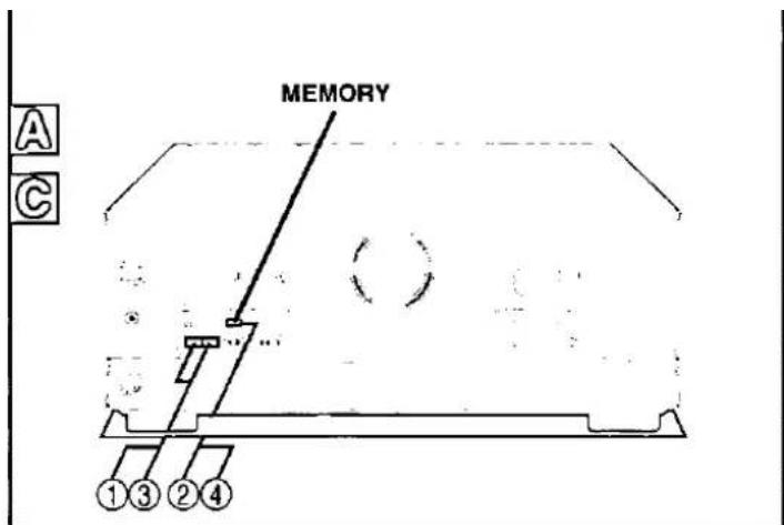
Press and hold [MEMORY].
The FM stations the unit can receive are preset in channels 1 to 30.
Presetting AM stations
Preparation: Tune to the AM frequency where you want presetting to begin (⇒ page 20).
Press and hold [MEMORY].
The AM stations the unit can receive are preset in channels 21 to 30. (FM stations are replaced if any were preset in these channels.)
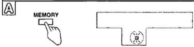
During automatic presetting, the memory indicator flashes and the frequency scrolls. The memory indicator and channel numbers are displayed for a second when a station is preset (B).
The last station to be preset is displayed when presetting finishes.
For your reference
Even if the power supply cord is disconnected from the household AC outlet, the stations remain in memory for approximately one month.
© Manual presetting
Preset the stations one at a time.
① Tune to the station.
② Press [MEMORY].
③ Press [TUNING ∨ or ∧] to select a channel.
④ Press [MEMORY].
D Selecting channels
1 Press [PRESET].
The channel number flashes for about 5 seconds.
2 Press [TUNING ∨ or ∧].
Hold down the buttons to change channels faster.
On the remote control
Press [CH ∨ or ∧].
or
Press the numbered buttons.
For channels 1 to 9, press the corresponding number.
For channels 10 or over, press [≥10], then the two digits.
e.g. To select channel 21 [≥10] → [2] → [1]

A

natural_image
Technical line drawing of a device casing with circular components and a labeled component (no text or symbols)TAPE MONITOR
1

B

C

Making a recording
Note
You cannot record a source connected through a digital terminal. When recording CD, DVD, or TV, ensure the source is connected through the corresponding analog terminals ( pages 6 and 7) and "ANALOG" input is selected ( page 17).
A Recording on a tape deck or VCR
You can record to a tape deck connected to TAPE REC (OUT) or to a VCR connected to VCR OUT.
See the recording unit's operating instructions for details on how to prepare it for recording.
When recording with a tape deck, you can record any source except TAPE.
When recording with a VCR, you can record any source except TAPE or VCR.
1 Turn [INPUT SELECTOR] to select the source to be recorded.
2 Begin recording.
Follow your recording unit's operating instructions.
3 Begin the source to be recorded.
Follow your equipment's operating instructions.

To monitor sound being recorded onto a tape deck
It is possible to check the sound being recorded if your tape deck is a 3 head system.
Press [TAPE MONITOR] on this unit and set the monitor button on the tape deck to "TAPE".
Press [TAPE MONITOR] once again to turn it off.

The HELP function
If you make a mistake in operation or if sound output stops, the HELP function displays information that indicates how you can remedy the situation.
If "ERROR" or scrolling characters ("SPEAKER OFF NOW", for example) appear on the display, do the following.
Press [-HELP, -RESET].
The remedy for the situation is displayed.
For your reference
You can reset the unit's settings to the factory settings. If this is ever necessary, press and hold [-HELP, -RESET] for about 2 seconds until "RESET" is displayed.
This will not erase radio stations you have preset.
Specifications (IHF'78)
□ AMPLIFIER SECTION
Rated minimum sine wave RMS power output 40 Hz–20 kHz both channels driven
0.9 % total harmonic distortion
100 W per channel (6 Ω)
1 kHz continuous power output both channels driven 0.05 % total harmonic distortion
105 W per channel (6 Ω)
| Total harmonic distortion | |
| rated power at 40 Hz–20 kHz | 0.9 % (6 Ω) |
| half power at 1 kHz | 0.07 % (6 Ω) |
Power output at 1 KHz each channel driven 0.9 % total harmonic distortion
| Front | 2 x 100 W (6 Ω) |
| Center | 100 W (6 Ω) |
| Surround | 2 x 100 W (6 Ω) |
| Low frequency damping factor | 30 (6 Ω) |
| Load impedance | |
| Front | 6-8 Ω |
| Center | 6-8 Ω |
| Surround | 6-8 Ω |
| Dynamic headroom | 2 dB (6 Ω) |
| Frequency response | |
| CD, TAPE, DVD, TV, VCR | 10 Hz-70 kHz, ±3 dB |
| Input sensitivity | |
| CD, TAPE, DVD, TV, VCR | 27 mV (200 mV, IHF '66) |
| S/N (IHF A) | |
| CD, TAPE, DVD, TV, VCR | 75 dB |
| Input impedance | |
| CD, TAPE, DVD, TV, VCR | 22 kΩ |
| Tone controls | |
| BASS | 50 Hz, +10 to -10 dB |
| TREBLE | 20 kHz, +10 to -10 dB |
| Subwoofer frequency response (-6 dB) | 7-200 Hz |
Digital Input
Optical
Coaxicial
□ FM TUNER SECTION
| Frequency range | 87.9–107.9 MHz |
| Sensitivity | 11.2 dBf (2 μV, IHF '58) |
| 50 dB quieting sensitivity | |
| MONO | 18.3 dBf (4.5 μV, IHF '58) |
| STEREO | 38.3 dBf (45 μV, IHF '58) |
| Total harmonic distortion | |
| MONO | 0.2 % |
| STEREO | 0.3 % |
| S/N | |
| MONO | 73 dB |
| STEREO | 67 dB |
| Frequency response | 20 Hz-15 kHz, +1 dB, -2 dB |
| Alternate channel selectivity | 65 dB |
| Capture ratio | 1.5 dB |
| Image rejection at 98 MHz | 40 dB |
| Spurious response rejection at 98 MHz | 75 dB |
| AM suppression | 50 dB |
| Stereo separation | |
| 1 kHz | 40 dB |
| 10 kHz | 30 dB |
| Antenna terminal | 75 Ω (unbalanced) |
□ AM TUNER SECTION
| Frequency range | 530–1710 kHz |
| Sensitivity | 20 μV, 330 μV/m |
| Selectivity | 55 dB |
| IF rejection at 1000 kHz | 50 dB |
□VIDEO SECTION
| Output voltage at 1 V input (unbalanced) | 1 ± 0.1 Vp-p |
| Maximum input voltage | 1.5 Vp-p |
| Input/output impedance | 75 Ω |
□GENERAL
| Power supply | AC 120 V, 60 Hz |
| Power consumption | 410 VA, 320 W |
| Dimensions (W x H x D) | 430 x 158 x 367 mm(16-15/16" x 6-7/32" x 14-15/32") |
| Mass | 9.1 kg (20.1 lb.) |
Power consumption in standby mode: 1 W
Maintenance
If the surfaces are dirty
To clean this unit, wipe with a soft, dry cloth.
If the surfaces are extremely dirty, use a soft cloth dipped in a soap-and-water solution or a weak detergent solution.
- Never use alcohol, paint thinner or benzine to clean this unit.
- Before using chemically treated cloth, read the instructions that came with the cloth carefully.
Notes:
- Specifications are subject to change without notice. Mass and dimensions are approximate.
- Total harmonic distortion is measured by the digital spectrum analyzer.
Product Service
Do not attempt to remove the cover (s) or repair the unit yourself.
Refer servicing to qualified personnel only.
Product information
For product service, product information or assistance with product operation, refer to the servicenter directory.
Troubleshooting guide
Before requesting service, make the checks below. If you can't fix the system as described below, or if something not listed here occurs, refer to the enclosed directory to locate an Authorized Service Center convenient to you or contact your dealer.
For detailed instructions, contact an authorized servicenter in the U.S.A. and Panasonic Canada Inc. Customer Care Centre in Canada. In the U.S.A., call 1-800-211-7262 or visit www.panasonic.com In Canada, call 905-624-5505 or visit www.panasonic.ca
| Common problems | Ref.Pages | |
| No power. | 9 | |
| 17 | ||
| 19 | ||
| 6-11 | ||
| 17 | ||
| No sound. | 19 | |
| 17 | ||
| 12-13 | ||
| 15 | ||
| 15 | ||
| Cannot select “DIGITAL” input. | 20 | |
| - | ||
| Sound stops. “OVERLOAD” appears on the display. | 10-11 | |
| - | ||
| “F 70” appears on the display. | - | |
| - | ||
| The picture doesn’t appear on the television. | - | |
| DSP sound modes | Ref.Pages | |
| Sound is not heard from the center, surround, or subwoofer speakers. | Ensure the size settings for your speakers are correct.Check the DSP sound mode.Cancel “DSP DEFEAT”. | 12-1315-1620 |
| DSP sound modes cannot be selected. | Cancel “DSP DEFEAT”. | 20 |
| Radio Ref/Pages | |
| The radio cannot be tuned in or there is a lot of noise and interference. | Adjust the position of the FM or AM antenna.Reduce the treble.Select "DSP DEFEAT".Turn off nearby televisions, video decks, DVD players, and satellite receivers.You may need an outdoor antenna or an antenna with more elements.Separate the antenna from other cables, leads, and appliances. |
Panasonic
Technics
Quāśār.
For Product Information, Operating Assistance, Literature Request, Dealer Locations, and all Customer Service inquiries please contact 1-800-211-PANA (7262), Monday=Friday 9 am=9pm; Saturday=Sunday 9 am=7pm, EST.
Web Site: http://www.panasonic.com You can purchase parts, accessories or locate your nearest servicenter by visiting our Web Site.
Accessory Purchases:
1-800-332-5368 (Customer Orders Only)
Panasonic Services Company 2042184th Avenue South, Kent, WA 98032
(6 am to 5 pm Monday-Friday; 6 am to 10:30 am Saturday; PST)
(Visa, MasterCard, Discover Card, American Express, Check)
Factory Servicenters Locations
| CALIFORNIA6550 Katella AvenueCypress, CA 90630800 Dubuque AvenueS. San FranciscoCA 9408020201 Sherman WaySuite 102Canoga Park, CA 913063878 Ruffin RoadSuite ASan Diego, CA 92123COLORADO1640 South Abilene StreetSuite DAurora, CO 80012FLORIDA3700 North 29thAvenueSuite 102Hollywood, FL 33020 | GEORGIA8655 Roswell RoadSuite 100Atlanta, GA 30350ILLINOIS9060 Golf RoadNiles, IL 607141703 North Randall RoadElgin, IL 60123(Pick-up/Drop-off only)MARYLAND62 Mountain RoadGlen Burnie, MD 21061MASSACHUSETTS60 Glacier DriveSuite GWestwood, MA 02090 | MICHIGAN37048 Van Dyke AvenueSterling Heights, MI 48312MINNESOTA7850-12thAvenue SouthAirport Business CenterBloomington, MN 55425OHIO2236 Waycross RoadCivic Center PlazaForest Park, OH 45240PENNSYLVANIA2221 Cabot Blvd. WestSuite BLanghorne, PA 19047 | TEXAS13615 Welch RoadSuite 101Farmers BranchTX 75244WASHINGTON20425-84thAvenue SouthKent, WA 98032 |
| HAWAII99-859Iwaiwa StreetAiea, Hawaii 96701Phone (808) 488-1996Fax (808) 486-4369 |
Service in Puerto Rico
Matsushita Electric of Puerto Rico, Inc. Panasonic Sales Company/Factory Servicenter Ave. 65 de Infanteria, Km. 9.5, San Gabriel Industrial Park, Carolina, Puerto Rico 00985 Phone (787) 750-4300 Fax (787) 768-2910
F04030 As of APR '00
Panasonic Consumer Electronics Company, Division of Matsushita Electric Corporation of America
One Panasonic Way, Secaucus, New Jersey 07094
Panasonic Sales Company, Division of Matsushita Electric Corporation of Puerto Rico, Inc.
Ave. 65 de Infantería, Km. 9.5, San Gabriel Industrial Park, Carolina, Puerto Rico 00985
Panasonic/Technics Audio Products Limited Warranty
Panasonic Consumer Electronics Company or Panasonic Sales Company (collectively referred to as "the warrantor") will repair this product with new or refurbished parts in the event of a defect in materials or workmanship, free of charge, in the U.S.A. or Puerto Rico as follows (all time periods start from the date of original purchase):
COMPACT DISC PLAYERS, DIGITAL VERSATILE DISC PLAYERS, RADIOS, RADIO CASSETTE PLAYERS/RECORDERS (with and without CD Players), CASSETTE RECORDERS, MICROCASSETTE RECORDERS/TRANSCRIBERS, IC RECORDERS, RECEIVERS, TUNERS, AMPLIFIERS, SUBWOOFER AMPLIFIERS, TURNABLES, CASSETTE DECKS, AUDIO PROCESSORS, EQUALIZERS, AUDIO MIXERS, REMOTE CONTROLS, HOME THEATER SYSTEMS (receiver/amplifiers, speakers), RACK SYSTEMS (receivers, tuners, amplifiers, cassette decks, CD players, equalizers, rack system speakers, EXCLUDING; audio racks)-labor and parts for one (1) year.
ALL AUDIO RACKS (cabinets)-parts only 30 days.
TECHNICS STAND ALONE SPEAKERS, SUBWOOFER SPEAKERS-labor and parts for three (3) years.
ACCESSORIES-HEADPHONES, CARTRIDGES, MICROPHONES, ADAPTERS-labor and parts for ninety (90) days.
BATTERIES—(when applicable)—New rechargeable batteries in exchange for defective rechargeable batteries for ten (10) days. Non-rechargeable batteries are not warranted.
RECHARGEABLE BATTERY PACKS—(when applicable)—New rechargeable battery packs in exchange for defective rechargeable battery packs for ninety (90) days. Non-rechargeable battery packs are not warranted.
Carry-in or mail-in service in the U.S.A. can be obtained during the warranty period by contacting a Panasonic Services Company (PASC) Factory Servicenter listed in the Servicenter Directory. Or call toll free, 1-800-211-7262 to locate a PASC authorized Servicenter. Carry-in or mail-in service in Puerto Rico can be obtained during the warranty period by calling the Panasonic Sales Company telephone number listed in the Servicenter Directory.
This warranty is extended only to the original purchaser. A purchase receipt or other proof of date of original purchase will be required before warranty service is rendered.
This warranty only covers failures due to defects in materials and workmanship which occur during normal use and does not cover normal wear to the stylus (when applicable) or a dealer installed cartridge or stylus. The warranty does not cover damages which occur in shipment or failures which are caused by products not supplied by the warrantor, or failures which result from accident, misuse, abuse, neglect, mishandling, faulty installation, misapplication, set-up adjustments, maladjustment of consumer controls, improper operation or maintenance, improper antenna, inadequate signal reception or pick-up, alteration, modification, power line surge, improper voltage supply, lightning damage, commercial use, such as; hotel, office, restaurant, or other business or rental use of the product, or service by anyone other than a PASC Factory Servicenter or a PASC authorized Servicenter, or damage that is attributable to acts of God.
LIMITS AND EXCLUSIONS
There are no express warranties except as listed above.
THE WARRANTOR SHALL NOT BE LIABLE FOR INCIDENTAL OR CONSEQUENTIAL DAMAGES RESULTING FROM THE USE OF THIS PRODUCT, OR ARISING OUT OF ANY BREACH OF THIS WARRANTY, INCLUDING WITHOUT LIMITATION, DAMAGE TO TAPES, RECORDS OR DISCS. ALL EXPRESS AND IMPLIED WARRANTIES, INCLUDING THE WARRANTIES OF MERCHANTABILITY, AND FITNESS FOR A PARTICULAR PURPOSE, ARE LIMITED TO THE APPLICABLE WARRANTY PERIOD SET FORTH ABOVE. Some states do not allow the exclusion or limitation of incidental or consequential damages, or limitations on how long an implied warranty lasts, so the above exclusions or limitations may not apply to you.
This warranty gives you specific legal rights and you may also have other rights which vary from state to state.
If a problem with this product develops during or after the warranty period, you may contact your dealer or Servicenter. If the problem is not handled to your satisfaction, then write to the Consumer Affairs Department at the company address indicated above.
If you ship the product
Carefully pack and send it prepaid, adequately insured and preferably in the original carton. Attach a postage-affixed letter, detailing the complaint, to the outside of the carton.
Do NOT send the product to the Executive or Regional Sales offices. They are NOT equipped to make repairs.
Customer's Record
| ModelNo. | Dealer'sName |
| SerialNo.or | |
| CodeNo. | Dealer'sAddress |
| DateofPurchase |
MEMO
Reference

Panasonic Consumer Electronics
Company, Division of Matsushita
Electric Corporation of America
One Panasonic Way Secaucus,
New Jersey 07094
http://www.panasonic.com
Panasonic Sales Company,
Division of Matsushita Electric of
Puerto Rico, Inc. ("PSC")
Ave. 65 de Infantería, Km. 9.5
San Gabriel Industrial Park, Carolina,
Puerto Rico 00985
Panasonic Canada Inc.
5770 Ambler Drive
Mississauga, Ontario
L4W 2T3
www.panasonic.ca
- Technics®
- AV Control Receiver
- Dear customer
- Supplied accessories
- Table of contents
- Before use
- Connections
- Preparations
- Operations
- Radio functions
- Reference
- CAUTION
- Listening caution
- THE FOLLOWING APPLIES ONLY IN THE U.S.A.
- CAUTION:
- WARNING:
- PRECAUTIONS
- Safety
- Installation
- Environment
- Placement
- Maintenance
- Service
- Control reference guide
- Main unit
- Display section
- Note
- Connecting video equipment
- Antenna connections
- To connect an outdoor antenna
- FM outdoor antenna
- AM outdoor antenna
- Connecting the AC power supply cord and other information
- "SWITCHED" AC outlet
- Conserving power
- Placement of speakers
- Front speakers
- Center speaker
- Surround speakers
- Subwoofer
- Connecting speakers
- Speaker impedance: 6-8 Ω
- To connect a passive subwoofer
- Or
- Customizing your receiver
- Setting descriptions
- SIZE
- DISTANCE
- FILTER
- DR COMP - Dynamic range compression
- D-INPUT - Digital input
- DIMMER
- Basic steps
- Changing the settings
- DR COMP
- D-INPUT
- Adjusting speaker output level
- Press [SPEAKERS] to turn on SPEAKERS.
- Press [TEST] to output the test signal.
- Adjust the volume to the level normally used.
- Press [LEVEL] to select the speaker channel to adjust.
- Press [-] or [+] to adjust the level to the same apparent level as the front speakers.
- Repeat steps 4 and 5 for each speaker channel.
- Press [TEST] to stop the test signal.
- For your reference
- DSP sound modes
- A STEREO mode
- B SURROUND mode
- Changing the recognition mode
- Press and hold [DIGITAL INPUT].
- A SFC modes
- HALL
- CLUB
- LIVE
- THEATER
- SIM SURR (Simulated Surround)
- B Adjusting the sound field
- To adjust the speaker level
- To adjust the delay time
- Enjoying the sounds
- When you finish listening
- A Adjusting the tone and balance
- 1
- Press [BASS/TREBLE, BALANCE].
- 2
- Press [-, L] or [+, R] .
- B
- Using headphones
- A Muting the volume
- Press [MUTING].
- To cancel
- B Adjusting the subwoofer level
- Press [SUBWOOFER LEVEL].
- To make finer adjustments
- C Using the TAPE MONITOR
- Press [TAPE MONITOR].
- The radio
- A Manual tuning
- Automatic tuning
- Improving reception
- FM mode
- DSP DEFEAT
- B Direct tuning
- Preset tuning
- Remember
- A Automatic presetting
- Presetting FM stations
- Press and hold [MEMORY].
- Presetting AM stations
- © Manual presetting
- D Selecting channels
- Press [PRESET].
- Press [TUNING ∨ or ∧].
- On the remote control
- Making a recording
- A Recording on a tape deck or VCR
- The HELP function
- Specifications (IHF'78)
- □ AMPLIFIER SECTION
- Rated minimum sine wave RMS power output 40 Hz–20 kHz both channels driven
- % total harmonic distortion
- If the surfaces are dirty
- Notes:
- Product Service
- Product information
- Troubleshooting guide
- Panasonic
- Technics
- Quāśār.
- Accessory Purchases:
- Panasonic/Technics Audio Products Limited Warranty
- LIMITS AND EXCLUSIONS
- If you ship the product
Marque : TECHNICS
Modèle : SA-DX750
Catégorie : Recepteur