
SA-EX320 - Recepteur TECHNICS - Notice d'utilisation et mode d'emploi gratuit
Retrouvez gratuitement la notice de l'appareil SA-EX320 TECHNICS au format PDF.


| Marque | Technics |
| Modèle | SA-EX320 |
| Type de produit | Récepteur stéréo AM/FM |
| Dimensions (L x H x P) | 430 x 140 x 370 mm |
| Poids | 8 kg |
| Alimentation | 220-240 V, 50/60 Hz |
| Consommation électrique | 200 W |
| Puissance de sortie | 2 x 50 W RMS (8 ohms) |
| Réponse en fréquence | 20 Hz - 20 kHz |
| Distorsion harmonique totale | < 0,05 % |
| Rapport signal/bruit | 80 dB |
| Entrées audio | Phono, CD, Aux, Tuner |
| Sorties audio | Enceintes (A/B), Casque |
| Fonctions principales | AM/FM stéréo, sélecteur d'entrée, tonalité, balance, loudness |
| Entretien et nettoyage | Dépoussiérer avec un chiffon doux et sec ; ne pas utiliser de produits chimiques |
| Sécurité | Ne pas obstruer les ouvertures de ventilation ; éviter les sources de chaleur |
| Prix indicatif | Environ 200-300 euros (occasion) |
FOIRE AUX QUESTIONS - SA-EX320 TECHNICS
Questions des utilisateurs sur SA-EX320 TECHNICS
0 question sur cet appareil. Repondez a celles que vous connaissez ou posez la votre.
Poser une nouvelle question sur cet appareil
Téléchargez la notice de votre Recepteur au format PDF gratuitement ! Retrouvez votre notice SA-EX320 - TECHNICS et reprennez votre appareil électronique en main. Sur cette page sont publiés tous les documents nécessaires à l'utilisation de votre appareil SA-EX320 de la marque TECHNICS.
MODE D'EMPLOI SA-EX320 TECHNICS
AV Control Stereo Receiver
SA-EX320
Operating Instructions

natural_image
Front view of a black electronic audio workstation with control panel and remote control (no visible text or labels)P
PC
Technics®
Before connecting, operating or adjusting this product, please read these instructions completely. Please save this manual.
RQT4166-P
Dear Customer
Thank you for purchasing this Technics product.
For optimum performance and safety, please read these instructions carefully.
Table of contents
Precautions....3
Supplied accessories....4
Listening caution....4
Concerning the remote control....5
Front panel controls....6
Equipment connections....7
Antenna connections 9
Speaker connections....11
Basic operations 13
To adjust the tone quality 14
To adjust the sound balance 14
To mute the sound level 14
To listen through headphones....14
Listening to radio broadcasts....15
Sequential tuning....15
Direct tuning 15
Preset tuning 16
Enjoying sound with DOLBY PRO LOGIC 18
Setting the center mode and adjusting speaker output level.....18
Enjoying SURROUND or 3 STEREO....20
Making a recording....21
Recording on a tape deck....21
Recording on a VCR....21
About the HELP function....22
Remote control operation....23
Troubleshooting guide 27
Technical specifications....Back cover
Product service ....Back cover
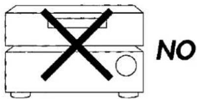
CAUTION
Do not place a tape deck or CD player on top of this unit.
Heat radiated from the top of this unit may cause damage to the tape or CD software.
User memo:
DATE OF PURCHASE ____
DEALER NAME ____
DEALER ADDRESS____
TELEPHONE NUMBER ____
The model number and serial number of this product can be found on either the back or the bottom of the unit.
Please note them in the space provided below and keep for future reference.
MODEL NUMBER
SERIAL NUMBER
THIS PHRASE IS APPLIED ONLY FOR U.S.A.
CAUTION:
Any unauthorized changes or modifications to this equipment would void the user's authority to operate this device.
WARNING:
TO REDUCE THE RISK OF FIRE, ELECTRIC SHOCK OR PRODUCT DAMAGE, DO NOT EXPOSE THIS APPLIANCE TO RAIN, SPLASHING, DRIPPING OR MOISTURE.
CAUTION:
TO PREVENT ELECTRIC SHOCK MATCH WIDE BLADE OF PLUG TO WIDE SLOT, FULLY INSERT.

CAUTION
RISK OF ELECTRIC SHOCK
DO NOT OPEN

CAUTION: TO REDUCE THE RISK OF ELECTRIC
SHOCK, DO NOT REMOVE SCREWS. NO USER-SERVICEABLE PARTS INSIDE.
REFER SERVICING TO QUALIFIED SERVICE PERSONNEL.

The lightning flash with arrowhead symbol, within an equilateral triangle, is intended to alert the user to the presence of uninsulated "dangerous voltage" within the product's enclosure that may be of sufficient magnitude to constitute a risk of electric shock to persons.

The exclamation point within an equilateral triangle is intended to alert the user to the presence of important operating and maintenance (servicing) instructions in the literature accompanying the appliance.
Precautions
Before using this unit please read these operating instructions carefully. Take special care to follow the warnings indicated on the unit itself as well as the safety suggestions listed below.
Afterwards keep them handy for future reference.
Safety
- Power Source – The unit should be connected to power supply only of the type described in the operating instructions or as marked on the unit.
- Polarization -- If the unit is equipped with a polarized AC power plug (a plug having one blade wider than the other), that plug will fit into the AC outlet only one way. This is a safety feature. If you are unable to insert the plug fully into the outlet, try reversing the plug. If the plug should still fail to fit, contact your electrician to replace your obsolete outlet. Do not defeat the safety purpose of the polarized plug.
- Power Cord Protection -- AC power supply cords should be routed so that they are not likely to be walked on or pinched by items placed upon or against them. Never take hold of the plug or cord if your hand is wet, and always grasp the plug body when connecting or disconnecting it.
- Nonuse Periods -- When the unit is not used, turn the power off. When left unused for a long period of time, the unit should be unplugged from the household AC outlet.
Installation
Environment
- Outdoor Antenna Grounding -- II an outside antenna is connected to the receiver, be sure the antenna system is grounded so as to provide some protection against voltage surges and built-up static charges. Section 810 of the National Electrical Code, ANSI/NFPA No. 70-1990, provides information with respect to proper grounding of the mast and supporting structure, grounding of the lead-in wire to an antenna discharge unit, size of grounding conductors, location of antenna-discharge unit, connection to grounding electrodes, and requirements for the grounding electrode. See figure below.

NEC-NATIONAL ELECTRICAL CODE
- Water and Moisture – Do not use this unit near water-for example, near a bathtub, washbowl, swimming pool, or the like. Damp basements should also be avoided.
- Heat - The unit should be situated away from heat sources such as radiators and the like. It also should not be placed in temperatures less than 5^ (41^) or greater than 35^ (95^) .
Placement
- Ventilation - The unit should be situated so that its location or position does not interfere with its proper ventilation. Allow 10cm (4") clearance from the rear of the unit.
- Foreign Material -- Care should be taken so that objects do not fall into and liquids are not spilled into the unit. Do not subject this unit to excessive smoke, dust, mechanical vibration, or shock.
- Magnetism -- The unit should be situated away from equipment or devices that generate strong magnetic fields.
- Stacking -- Do not place heavy objects, other than system components, on top of the unit.
- Surface -- Place the unit on a flat, level surface.
- Carts and Stands -- The unit should be used only with a cart or stand that is recommended by the manufacturer. The unit and cart combination should be moved with care.
Quick stops, excessive force, and uneven surfaces may cause the unit and cart combination to overturn.

- Wall or Ceiling Mounting -- The unit should not be mounted to a wall or ceiling, unless specified in this operating instructions.
Maintenance
Clean the cabinet, panel and controls with a soft cloth lightly moistened with mild detergent solution.
Do not use any type of abrasive pad, scouring powder or solvent such as alcohol or benzine.
Service
- Damage Requiring Service – The unit should be serviced by qualified service personnel when:
(a) The AC power supply cord or the plug has been damaged; or (b) Objects have fallen or liquid has been spilled into the unit; or
(c) The unit has been exposed to rain; or
(d) The unit does not appear to operate normally or exhibits a marked change in performance; or
(e) The unit has been dropped, or the enclosure damaged. - Servicing -- The user should not attempt to service the unit beyond that described in the operating instructions. All other servicing should be referred to an authorized service personnel. (Only for U.S.A.)
Call 1-800-545-2672 for the address of an authorized factory servicenter.
Please check and identify the supplied accessories.


natural_image
Technical line drawing of a mechanical assembly with wires, connectors, and a screw (no text or symbols)




Supplied accessories
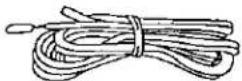
③ AC power supply cord (SJA172)....1 pc.
(b) AM loop antenna set (RSA0010)
- AM loop antenna....1 pc.
- AM loop antenna holder .... 1 pc.
- Screw ....1 pc.
© FM indoor antenna (RSA0006)....1 pc.
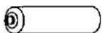
(d) Batteries....2 pcs.
⑧ Remote control transmitter (EUR644347) ....1 pc.
Use numbers indicated in parentheses when asking for replacement parts.
(Only for U.S.A.)
To order accessories call PASC Accessory Dept. 1-800-332-5368.
Listening caution


Selecting fine audio equipment such as the unit you've just purchased is only the start of your musical enjoyment. Now it's time to consider how you can maximize the fun and excitement your equipment offers. This manufacturer and the Electronic Industries Association's Consumer Electronics Group want you to get the most out of your equipment by playing it at a safe level. One that lets the sound come through loud and clear without annoying blaring or distortion-and, most importantly, without affecting your sensitive hearing.
We recommend you to avoid prolonged exposure to excessive noise.
Sound can be deceiving. Over time your hearing "comfort level" adapts to higher volumes of sound. So what sounds "normal" can actually be loud and harmful to your hearing.
Guard against this by setting your equipment at a safe level BEFORE your hearing adapts.
To establish a safe level:
- Start your volume control at a low setting.
- Slowly increase the sound until you can hear it comfortably and clearly, and without distortion.
Once you have established a comfortable sound level:
- Set the dial and leave it there.
Taking a minute to do this now will help to prevent hearing damage or loss in the future. After all, we want you listening for a lifetime.
A

Insert the batteries in the correct polarities (⊕, ⊖).
B
Remote control signal sensor

Concerning the remote control
Battery installation
A
- Thoroughly clean the battery compartment before inserting new batteries.
- Do not mix old and new batteries, or batteries of different types (carbon and alkaline, etc.).
- If you will not use the remote control for a long period of time, remove the batteries and store them in a cool, dark place.
- Do not use rechargeable type batteries.
- Do not attempt to recharge alkaline or carbon batteries.
- Always remove old, weak or worn-out batteries promptly and dispose of them properly.
- Never subject batteries to excessive heat or flame; do not attempt to disassemble them; and be sure they are not short-circuited.
- If the leaking electrolyte comes into contact with skin or clothes, flush with water immediately.
When you need to replace these batteries
Use two R6/LR6, AA, UM-3 batteries.
Method for use
B
Note
Be sure the transmission window and the signal sensor are free from dust. Excessive dust might affect performance.
The operation may not be correct if direct sunlight or another strong light source strikes the signal sensor of this unit. If there is a problem, place the unit away from the light source.

Front panel controls
① Power "STANDBY ⏻/ON" switch
(POWER, STANDBY ⏻/ON)
Press to switch the unit from on to standby mode or vice versa.
In standby mode, the unit is still consuming a small amount of power.
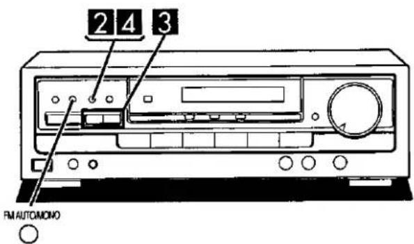
② Tuning buttons (TUNING)
③ Band select button (BAND)
④ FM mode select button (FM AUTO/MONO)
⑤ Memory button (MEMORY)
⑥ Help/reset button (-HELP -RESET)
⑦ Preset channel buttons (PRESET)
⑧ Remote control signal sensor (SENSOR)
⑨ DOLBY PRO LOGIC OFF ON button (OFF/ON)
⑩ DOLBY PRO LOGIC mode select button (□□ PRO LOGIC)
⑪ Center mode select button (CENTER MODE)
⑫ Display
⑬ Muting button (MUTING)
⑭ Headphones jack (PHONES)
⑮ Speaker ON/OFF button (SPEAKERS)
⑯ Input select buttons
⑰ Tape monitor button (TAPE MONITOR)
⑱ Bass control (BASS)
⑲ Treble control (TREBLE)
⑳ Balance control (BALANCE)
② Volume control (VOLUME)
Make sure that the power supply for all components has been turned off before making any connections.
To connect equipment, refer to the appropriate operating instructions.
Note
Do not place books, etc., on the top of this unit or block the heat radiation vents in any way.
Connecting audio equipment
Stereo connection cable (not included)


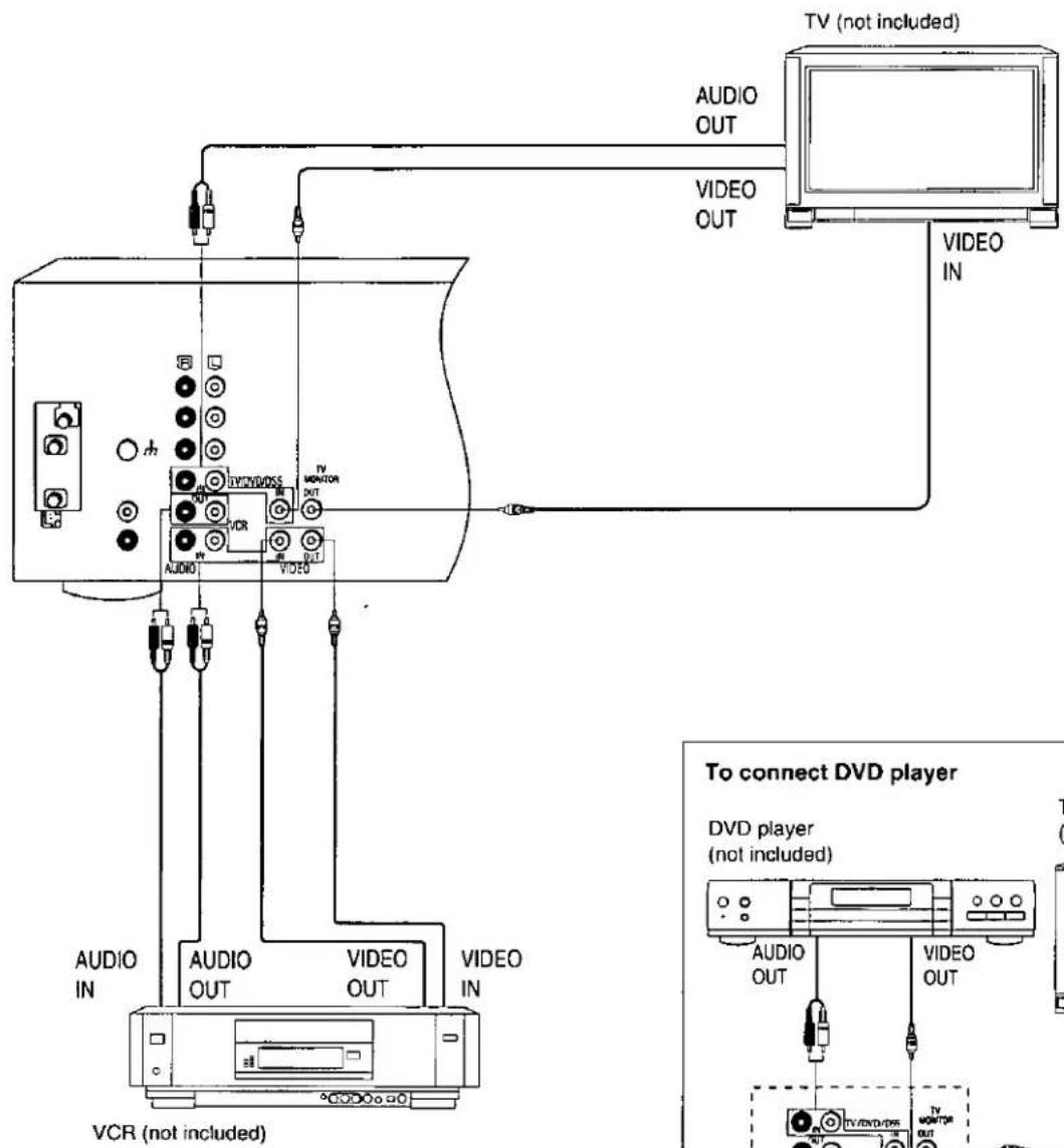
Connecting video equipment
Stereo connection cable (not included)
White
(L)
Red
(R)
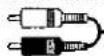

Video connection cable (not included)



Antenna connections
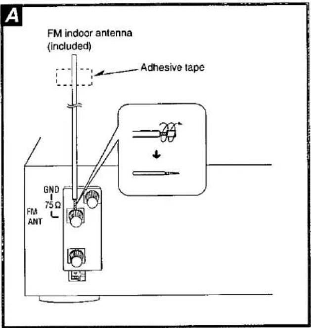
FM indoor antenna (included)
A
This antenna is normally sufficient for reception of FM broadcasts.
Attach to a wall (using a tape) facing in the direction of best reception.
For best reception
An FM outdoor antenna is recommended.
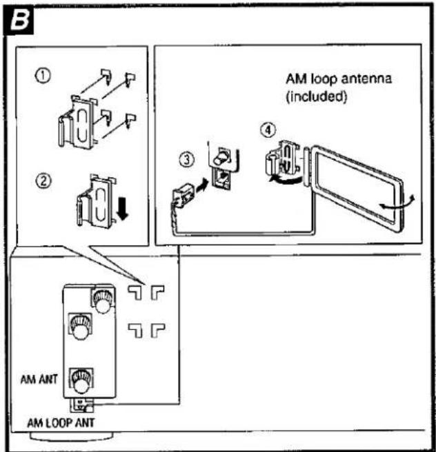
AM loop antenna (included)
8
This antenna is normally sufficient for reception of AM broadcasts.
Fit the AM loop antenna holder (included) onto the rear panel of this unit and then attach the AM loop antenna to the AM loop antenna holder (facing in the direction of best reception).
Pay attention to the following points when mounting the antenna.
- Do not mount it close to power cords, speaker wires or metal surfaces (Doing so will result in noise).
- Do not mount it close to a tape deck. When the tape deck is being used, chirping or beeping sounds may result.
When mounting the antenna to a column, a wall or rack C
Mount the antenna so that the hinge is vertical.

FM outdoor antenna (not included)
A
An outdoor antenna should be used when using this unit in mountainous areas or in spaces enclosed by reinforced concrete where the FM indoor antenna (included) does not provide satisfactory reception.
Disconnect the FM indoor antenna if an FM outdoor antenna is installed.
Note
An outdoor antenna should be installed by a qualified technician only.
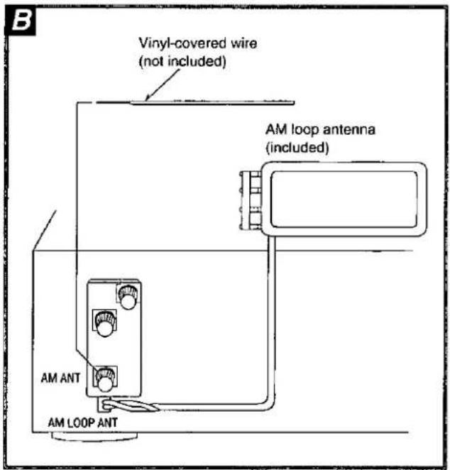
AM outdoor antenna (not included)
B
An outdoor antenna should be used when using this unit in mountainous areas or in spaces enclosed by reinforced concrete where the AM loop antenna (included) does not provide satisfactory reception.
Stretch 5–12 m (16–40 ft.) of vinyl-covered wire horizontally across a window frame or other convenient location, keeping it as high as possible from the ground.
When the unit is not in use, disconnect the outdoor antenna to prevent possible damage that may be caused by lightning. Never use an outdoor antenna during an electrical storm.
Note
Be sure to connect the AM loop antenna even when an outdoor antenna is used.
Placement of speakers
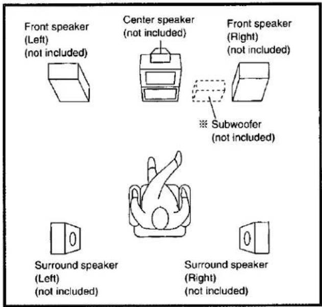
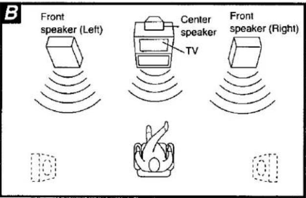
As well as enjoying normal stereo reproduction with the left and right front speakers, a center speaker and surround speakers can also be connected to this unit in order to enjoy the sound performance of Dolby Pro Logic Systems.
We recommend that surround speakers be placed on the side of or slightly behind the listener, and about one meter higher than ear level.
However the position should be adjusted to your personal preference, because the effect varies to some degree depending upon the sources.
※ The subwoofer can be placed in any position.
Connecting speakers
Note
Other connections are possible depending on the speaker system you have.
For details, see the operating instructions that came with your speaker system.
Speaker cable (not included)

Front speakers

Speaker impedance: 8 Ω
Center speaker and Surround speakers

Note
- Before sound can be heard, both surround speakers must be connected.
- Do not connect the surround speakers to the front speaker terminals. The surround speakers may be damaged if connected to the front terminals.
Speaker impedance:
Center speaker: 8 Ω
Surround speakers: 4-8 Ω
Subwoofer
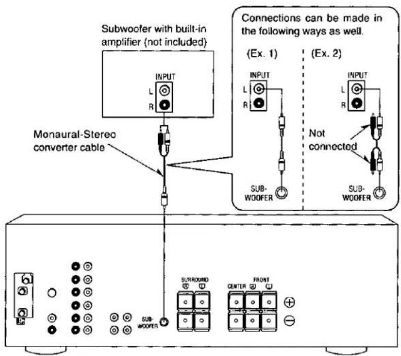
Note
This receiver has no amplifier section designed especially for the subwoofer.
To connect a subwoofer which does not have a built-in amplifier
Connect an optional amplifier to the "SUB-WOOFER" terminal of this unit and then connect a subwoofer to the speaker terminals of the amplifier.
Connecting the speaker cable


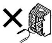
Note
To prevent damage to circuitry, never short-circuit positive (+) and negative (−) speaker wires.

1

2

3

4
A
Basic operations
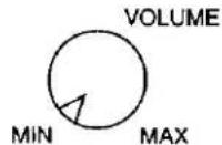
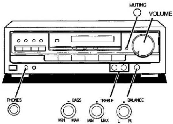
Before operation, set VOLUME to the "MIN" position.
1 Press POWER.
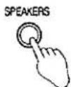
2 Press SPEAKERS and check the "SPEAKERS" indication lights up.
If the button is pressed once more, the indicator will switch off and no sound will be heard from the speakers.
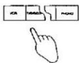
3 Press to select the desired source, and start the desired source.
(Refer to the appropriate operating instructions for details.)
VCR: To watch video tapes (VCR)
TV/DVD/DSS: To watch TV, DVD or DSS
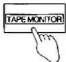
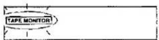
TAPE MONITOR: To listen to cassette tapes (The tape monitor indicator will appear.)
(See below.)
CD: To listen to compact discs
TUNER: To listen to radio broadcasts
PHONO: To listen to phono discs
Note
To watch a video (or DVD) or the TV, set the TV to either the TV mode or VIDEO mode as indicated below.
• To enjoy videos (or DVD)
Set it to VIDEO mode.
• To watch TV
Set it to TV mode.
4 Turn VOLUME to adjust the volume level.
After listening is finished
Be sure to reduce the volume level, and switch the power to the standby condition by pressing POWER.
When the tape monitor indicator is lit or flashing A
This indicates that the tape monitor function of this unit is ON.
To listen to sources other than a tape, be sure to press
TAPE MONITOR and check the indicator goes out.
A


B

C

D

②

Basic operations
A
To adjust the tone quality
Turn BASS to adjust the low frequency sound. Turn TREBLE to adjust the high frequency sound.
To adjust the sound balance
B
Turn BALANCE to adjust the left/right sound balance.
To mute the sound level
C
Press MUTING.
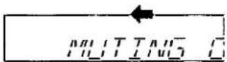
The message "MUTING ON NOW" runs repeatedly from right to left across the display as long as the muting function is on.
Press once again to return to the previous volume level.
Note
When the receiver is turned off, the muting operation will be automatically cancelled.
To listen through headphones
D
① Use VOLUME to reduce the volume level.
② Connect the headphones.
Plug type: 6.3 mm (1/4 in.) stereo
③ Use VOLUME to adjust the volume level.
If you do not want sound from the speakers, press SPEAKERS button and check the speaker indicator goes out. If a subwoofer is connected to your system, turn off power to it (or the subwoofer amp you are using) or lower the volume to the minimum level.
Note
Avoid listening for prolonged periods of time to prevent hearing damage.
A

1

2


3


B
1

2
3

Listening to radio broadcasts
Sequential tuning

You can use the tuning buttons to tune-in radio stations.

Press TUNER.

Press BAND to select "FM" or "AM".

Press TUNING (∨) or (∧) to tune to the desired frequency.
Tuning intervals
FM: 0.2 MHz
AM: 10 kHz
"QUARTZ LOCK" lights up when tuned.
"STEREO" lights up when an FM stereo broadcast is received.
To make an automatic search for broadcast stations
If TUNING (V) or (A) is held down for an instant until the frequency begins to scroll, the broadcast stations can be tuned in automatically when a broadcast station is found.
Note
Tuning may stop automatically if any jamming is encountered.
If noise is excessive in the FM stereo mode
Press FM AUTO/MONO.
(The "STEREO" indicator will go out, and the "MONO" indicator will light up.)
The broadcast will be monaural, but noise will be reduced.
If the button is pressed once more, the stereo mode will be resumed.
Direct tuning

(Only available from the remote control.)
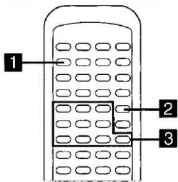
Specify the frequency using the numeric buttons on the remote control transmitter to directly tune to the desired station.
First select between FM and AM with the BAND button on the receiver.

Press TUNER.
This will set the remote control to operate the tuner.

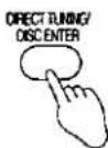
Press DIRECT TUNING/DISC ENTER.

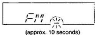
Press the appropriate numeric buttons to enter the frequency, while cursor display is flashing.
Tuning intervals
FM: 0.1 MHz
AM: 10 kHz
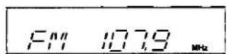
If the desired FM frequency is 107.9 MHz, press
$$ \boxed {1} \rightarrow \boxed {0} \rightarrow \boxed {7} \rightarrow \boxed {9} $$
If the frequency has been input correctly, the displayed frequency will blink once.
Note
-
If no button is pressed while the cursor display is flashing, the display will return to the frequency which is currently being received. To re-specify the frequency, repeat the procedure from step 2.
-
If the frequency has not been input correctly, "ERROR" indication will be displayed. In this case, re-enter the frequency.


Listening to radio broadcasts
Preset tuning
Presetting radio stations into the memory channels of this unit makes selecting stations simple.
A total of 30 FM and AM stations can be preset.
Please remember this
If a new broadcast station is preset into a channel, the setting for the broadcast station which was previously entered in that channel will be automatically erased.
Automatic memory presetting
Automatic memory presetting allows this unit to automatically search for broadcast stations and then preset them into memory. With this method, the channels that can be preset into the memory are set as follows for different bands (FM or AM).
When FM stations are preset,
For FM stations....1-30
When FM and AM stations are preset,
For FM stations....1-20
For AM stations....21-30
1 Set to the frequency from which you want to start automatic memory presetting.
(See page 15.)
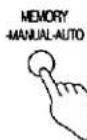
2 Press MEMORY until the frequency begins to change.
(Automatic memory presetting will start.)
During automatic memory presetting, the memory indicator will flash while the frequency scrolls.
To stop, press MEMORY once again.
When a broadcast station is preset A
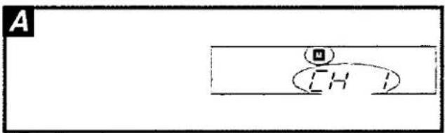
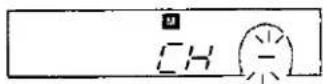
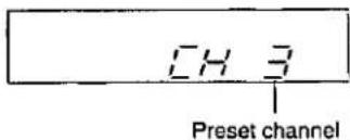
The memory indicator and the preset channel number will be displayed for approximately 1 second.
When presetting is completed
The last broadcast station to be preset will be displayed.
Note
Frequencies may not be preset correctly in cases where the broadcast waves are too strong or too weak. In such cases, carry out presetting manually. (See page 17.)
A
1

2

3

4

B
1

Listening to radio broadcasts
Manual memory presetting

The desired stations can be preset into the desired channels by the user.

Set to the desired frequency.
(See page 15.)
If interference or static is keeping you from enjoying an FM station, press FM AUTO/MONO and change to monaural. You can preset the memory in monaural just as in stereo.

Press MEMORY.
To cancel the memory function, press MEMORY again.

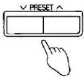
Press PRESET (∨) or (∧) to select the desired channel.
Holding the buttons down lets you scroll through channels faster.

Press MEMORY.
The channel will blink on the display.
To continue presetting
Repeat steps 1 through 4.
To listen to preset channels


Press PRESET (∨) or (∧) to select the desired channel.
Holding the buttons down lets you scroll through channels faster.
To confirm the channel number of the broadcast station being received
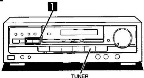
Press TUNER.
(The channel number will be displayed for approximately 1 second.)
Note
The channel number is not displayed if you change the reception frequency or FM mode setting.
For your reference
Even if the power is switched to standby or the power cord is disconnected from the household AC outlet, the memory will retain its contents for approximately one month.
If frequency presettings are accidentally erased
Program the presettings once again.
The power cord should remain connected for one hour or more for the memory back-up to be effective.

C


Enjoying sound with DOLBY PRO LOGIC
Dolby Pro Logic lets you enjoy movie software (video tapes and laser discs) in your own home with the same powerful stereophonic effect found in movie theaters. This unit has two Dolby Pro Logic modes: SURROUND and 3 STEREO.
SURROUND A
By reproducing the feeling of depth and movement of sound, video software or compact discs recorded with Dolby Surround provide the listener with a feeling of presence like that of a movie theater.
3 STEREO B
You can enjoy audio/video sources with clear sound, more presence and a good feeling of orientation. 3 STEREO can be used with stereo sources not encoded with DOLBY SURROUND.
Setting the center mode and adjusting speaker output level
C
Note
- When ready to adjust speaker output level, situate yourself whose you would normally be listening.
- First turn ON the speakers with the SPEAKERS button on the receiver.
- If the front speaker volume is unbalanced, adjust the balance with the BALANCE knob.
- You cannot adjust the output level of the subwoofer by using this receiver.
1
Press ☐☐ PRO LOGIC to turn on the Dolby Pro Logic system and select the desired mode.
When the button is pressed, the Dolby Pro Logic mode is displayed for approximately 1 second only.
Pressing it again changes the Dolby Pro Logic mode.
2
Press CENTER MODE to select the correct center mode.
When the button is pressed, the current center mode is displayed.
Pressing it again changes the center mode.
NORMAL
When the center speaker is smaller than the front speakers. WIDEBAND
When the center speaker is the same size as or larger than the front speakers.
PHANTOM SURROUND mode only
When no center speaker is connected.
Note
In the PHANTOM mode, the sound which would have been sent to the center speaker will be divided equally between both the left and right front speakers.
(Continued on next page)

3

TEST L
4

5

C 0.0B
6

C +3.48
Enjoying sound with DOLBY PRO LOGIC
3
by remote control only
Press TEST to output a test signal.
The speaker outputting the test signal is displayed while the test is running.
L: Front speaker (Left)
C : Center speaker
R : Front speaker (Right)
S : Surround speakers
For SURROUND mode
$$ \begin{array}{c}\text {L} \rightarrow \text {C} \rightarrow \text {R} \rightarrow \text {S}\\text {↓}\end{array} $$
In the PHANTOM mode, the center speaker is OFF, so there is no center test signal and "C" is not displayed.
For 3 STEREO mode
$$ \begin{array}{c}L \rightarrow C \rightarrow R\\hline\end{array} $$
4
by remote control
Press VOLUME (−) or (+) to set the volume level normally used for enjoying the source.
The following steps are for setting the output level of the front speakers and the center/surround speakers to the same listening level.
5
by remote control only
Press CH SELECT to select the center or surround speakers.
6
by remote control only
Press CH LEVEL (−) or (+) to adjust the output level.
Adjust the output level of each speaker from the listening position until they are all identical.
-: Decrease the output level.
+: Increase the output level.
Output level can be varied within a range of -12 dB to +12 dB with front speaker output level serving as the zero point.
Note
- During steps 5 and 6 above the test signal sequence is interrupted and the signal will only come from the selected speaker.
The sequence will resume when adjustments are stopped. - Remember you cannot adjust the output level of the surround speakers if you selected the 3 STEREO mode in step 1.
To stop the test signal
Press TEST.
To turn off the Dolby Pro Logic systems
Press OFF/ON.
Press once again to turn it on.

1

2
Enjoying SURROUND or 3 STEREO
1 Select and start the desired source.
2 Press ☐ PRO LOGIC to turn on the Dolby Pro Logic system and select the desired mode.
When the button is pressed, the Dolby Pro Logic mode is displayed.
Pressing it again changes the Dolby Pro Logic mode.
Note
When employing SURROUND, use software recorded in Dolby Surround.
For your reference
You can set the Dolby Pro Logic mode for each source.
Each source will retain the selected mode.
To turn off the Dolby Pro Logic systems
Press OFF/ON.
Manufactured under license from Dolby Laboratories Licensing Corporation.
DOLBY, the double-D symbol ☐ and "PRO LOGIC" are trademarks of Dolby Laboratories Licensing Corporation.
A

1

B
C

natural_image
Line drawing of a computer front panel with buttons and a dial (no text or symbols)1

Making a recording
A
Recording on a tape deck
Before recording, prepare the tape deck for recording (recording level adjustment, etc.).
See the tape deck's operating instructions for details.

Select the source to be recorded.
Any source can be selected except TAPE MONITOR

Begin recording on the tape deck.
Follow your tape deck's operating instructions.

Begin the desired source to be recorded.
Follow your equipment's operating instructions.
To check the sound recorded while a recording is being made B
It is possible to check the sound being recorded if your tape deck is a 3 head system.
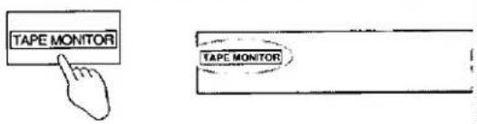
Press TAPE MONITOR on this unit and set the monitor button on the tape deck to "TAPE".
Press TAPE MONITOR once again to turn it off.
Recording on a VCR
C
Before recording, prepare the VCR for recording (recording level adjustment, input selector setting, etc.).
See the VCR's operating instructions for details.

Select the audio source to be recorded.
Press either TV/DVD/DSS, CD, TUNER or PHONO to select the source you want to record from.
Note
Recording from the tape deck is not possible.

Begin recording on the VCR.
Follow your VCR's operating instructions.

Begin the source to be recorded.
Follow your equipment's operating instructions.
About the HELP function
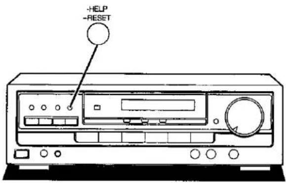
If you make a mistake in operation or if sound output stops due to some operation which was performed, the HELP function displays information which can be useful for indicating the method by which this condition can be remedied.
If "ERROR" or scrolling characters (for instance, "TAPE MONITOR ON NOW") appear on the display during operation, carry out the following operation.
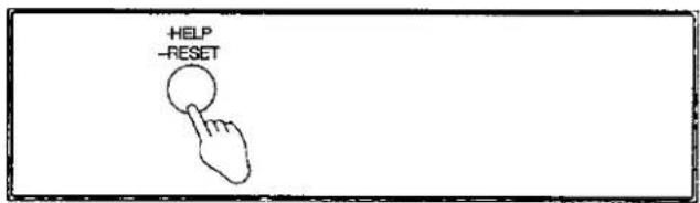
Press -HELP.
(Touch only.)
The method for remedying this situation will be displayed.
For your reference
If the above button is pressed for 2 seconds or more until "RESET" appears on the display, the operation settings for the unit will be initialized to the settings made at the time of shipment.
However, any broadcasting stations which have been preset into memory will not be erased at this time.
Remote control operation
This remote control can be used to operate the receiver you purchased and some other Panasonic and Technics compact cassette decks, CD changers (and CD players), TVs, VCRs and laser disc players, provided they are equipped with the remote control sensor.
- For an explanation on how to set up your remote control and precautions, see page 5.
- For details on operating other equipment, see the instruction manual provided with the specific unit.
| To operate the receiver | ||
Facing toward the receiver | Basic operations | |
| To turn the power ON/OFF |  Once the power has been set to ON, it can be turned ON and OFF simply by pressing POWER. Once the power has been set to ON, it can be turned ON and OFF simply by pressing POWER. | |
| To select an input source |  • PHONO can not be selected with this remote control. • Selecting TAPE MONITOR turns ON the tape monitor function. Pressing it again or another input select button turns the function OFF. • PHONO can not be selected with this remote control. • Selecting TAPE MONITOR turns ON the tape monitor function. Pressing it again or another input select button turns the function OFF. | |
| To mute the sound level |  The message "MUTING ON NOW" runs repeatedly from right to left across the display as long as the mut-ing function is on. Press once more to return to the original volume. The message "MUTING ON NOW" runs repeatedly from right to left across the display as long as the mut-ing function is on. Press once more to return to the original volume. | |
| To adjust the volume level |  | |
| NoteAfter turning the power of the TV, VCR or laser disc player ON or OFF, always press TUNER before pressing POWER when turning the power of the receiver ON and OFF. | ||
Facing toward the receiver↑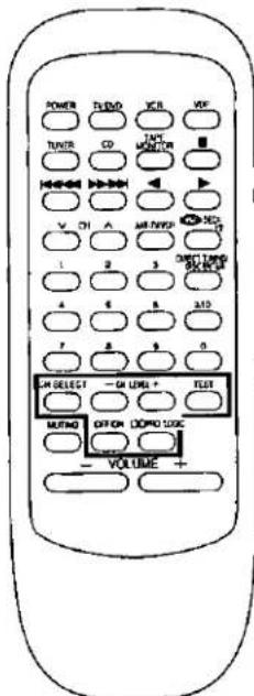 | To use Dolby Pro Logic | |
| To turn on Dolby Pro Logic and select the desired mode | Changes as follows each time the button is pressed.SURROUND ⇌ 3 STEREO | |
| To output a test signal | When the SURROUND or 3 STEREO mode is ONTESTPress once more to stop the test signal. | |
| To adjust the output level of center speaker and/or surround speakers | When the SURROUND or 3 STEREO mode is ONCH SELECT1Selects channel between center (C) and surround (S).↓-CH LEVEL↓○○○NoteWhen the SURROUND mode is ON and the center mode is on PHANTOM, you cannot select the center channel. When the 3 STEREO mode is ON, you cannot select the surround channel. | |
| To turn Dolby Pro Logic OFF and ON | OFF/ON○ | |
| To operate the receiver (continued) | ||
| Facing toward the receiver | To listen to radio broadcasts | |
| To switch the remote control transmitter to tuner operation mode | TUNER Be sure to press this button before operating the receiver. | |
 | To select the desired channel sequentially (Preset tuning) |  |
| To select the desired channel directly (Preset tuning) | 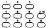 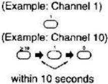 | |
| To select radio stations by frequency (Direct tuning) | First select between FM and AM with the BAND button on the receiver. 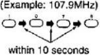 | |
| To operate CD changer (or CD player)Turn the CD changer (or CD player) ON before trying to operate it by remote control. | ||
| Facing toward the CD changer (or CD player) | To switch the remote control to CD changer (or CD player) operation mode | Be sure to press this button before operating the CD changer or CD player. |
| To start play |  | |
| [CD changer only] To start play from the desired disc | For 5 CD changer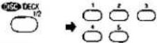 Select disc number. Select disc number. | |
For MEGA CD changer * Select disc number. (When selecting discs, the ≥10 button does not respond to touch.)For your reference Select disc number. (When selecting discs, the ≥10 button does not respond to touch.)For your reference If you press this button instead of the ▶button shown in the above procedure, the CD changer will stop and display the disc number. To start the disc, press ▶. If you press this button instead of the ▶button shown in the above procedure, the CD changer will stop and display the disc number. To start the disc, press ▶. | ||
| To start play from the desired track |   | |
| To skip a track |  (Backward) (Forward) (Backward) (Forward) | |
| To stop play |  | |
※ "MEGA CD changer" means any Technics CD changer that takes more than 50 discs.
| To operate a cassette deckTurn the cassette deck ON before trying to operate it by remote control. | |||
Facing toward the cassette deck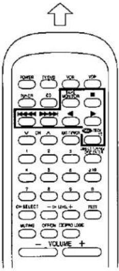 | To switch the remote control transmitter to cassette deck operation mode |  | Be sure to press this button before operating the cassette deck. |
| Only when using a double cassette deckTo select the tape deck (DECK 1/DECK 2) |  | The remote control indicator of the cassette deck will change each time the button is pressed. | |
| To start playback |   | ||
| To fast-forward or rewind the tape | While the tape is stopped With TPS-equipped cassette decks you can move to the beginning of a track by pressing these buttons while the tape is playing. With TPS-equipped cassette decks you can move to the beginning of a track by pressing these buttons while the tape is playing. | ||
| To stop playback |  | ||
You can operate the following cassette decks, CD changers and CD players with this remote control. (As of February 1998)
| Cassette deck | RS-TR373, RS-TR474, RS-TR575, RS-BX501, RS-TR252, RS-TR262, RS-TR272 |
| CD changer or CD player | SL-PG440, SL-PD847, SL-PD947, SL-PS840, SL-PD667, SL-P9066, SL-PD867, SL-PD967, SL-PD1000, SL-PD687, SL-PD688, SL-PD787, SL-PD788, SL-PD887, SL-PD888, SL-PD987, SL-PD988, SL-PD1010, SL-MC50, SL-MC60, SL-MC300, SL-MC310, SL-MC400, SL-MC410, SL-MC700 |
Some of the above models are not sold in certain areas.
| To operate a laser disc playerThe below procedures are examples for when a laser disc player is connected to the "TV/DVD/DSS" terminals of the receiver. | |||
 | Facing toward the TV facing toward the laser disc player TV/DVD → POWER → Switch ON the power for TV. Switch ON the power for laser disc player. | Facing toward the laser disc player Set the TV/VIDEO mode on the TV to "VIDEO". Facing toward the laser disc player Play will begin. | |
| To search for a position | In the play mode VDP ↔ ↗ ↗ ↗ ↗ ↗ ↗ ↗ ↗ ↗ ↗ ↗ ↗ ↗ ↗ ↗ ↗ ↗ ↗ ↗ ↗ ↗ ↗ ↗ ↗ ↗ ↗ ↗ ↗ ↗ ↗ ↗ ↗ ↗ ↗ ↗ ↗ ↗ ↗ ↗ ↗ ↗ ↗ ↗ ↗ ↗ ↗ ↗ ↗ ↗ ↗ ↘ ↗ ↗ ↗ ↗ ↗ ↗ ↗ ↗ ↗ ↗ ↗ ↗ ↗ ↗ ↗ ↗ ↗ ↗ ↗ ↗ ↗ ↗ ↗ ↗ ↗ ↗ ↗ ↗ ↗ ↗ ↗ ↗ ↗ ↗ ↗ ↗ ↗ ↗ ↗ ↗ ↗ ↗ ↗ ↗ ↗ ↗ ↗ ↗ ↗ ↓ ↗ ↗ ↗ ↗ ↗ ↗ ↗ ↗ ↗ ↗ ↗ ↗ ↗ ↗ ↗ ↗ ↗ ↗ ↗ ↗ ↗ ↗ ↗ ↗ ↗ ↗ ↗ ↗ ↗ ↗ ↗ ↗ ↗ ↗ ↗ ↗ ↗ ↗ ↗ ↗ ↗ ↗ ↗ ↗ ↗ ↗ ↗ ↗ ↗ ↕ ↕ ↕ ↕ ↕ ↕ ↕ ↕ ↕ ↕ ↕ ↕ ↕ ↕ ↕ ↕ ↕ ↕ ↕ ↕ ↕ ↕ ↕ ↕ ↕ ↕ ↕ ↕ ↕ ↕ ↕ ↕ ↕ ↕ ↕ ↕ ↕ ↕ ↕ ↕ ↕ ↕ ↕ ↕ ↕ ↕ ↕ ↕ ↕ ↕ ↵ ↕ ↕ ↕ ↕ ↕ ↕ ↕ ↕ ↕ ↕ ↕ ↕ ↕ ↕ ↕ ↕ ↕ ↕ ↕ ↕ ↕ ↕ ↕ ↕ ↕ ↕ ↕ ↕ ↕ ↕ ↕ ↕ ↕ ↕ ↕ ↕ ↕ ↕ ↕ ↕ ↕ ↕ ↕ ↕ ↕ ↕ ↕ ↕ ↕ ↅ ↕ ↕ ↕ ↕ ↕ ↕ ↕ ↕ ↕ ↕ ↕ ↕ ↕ ↕ ↕ ↕ ↕ ↕ ↕ ↕ ↕ ↕ ↕ ↕ ↕ ↕ ↕ ↕ ↕ ↕ ↕ ↕ ↕ ↕ ↕ ↕ ↕ ↕ ↕ ↕ ↕ ↕ ↕ ↕ ↕ ↕ ↕ ↕ ↕ ↕ ↕ ↕ ↕ ↕ ↕ ↕ ↕ ↕ ↕ ↕ ↕ ↕ ↕ ↕ ↕ ↕ ↕ ↕ ↕ ↕ ↕ ↕ ↕ ↕ ↕ ↕ ↕ ↕ ↕ ↕ ↕ ↕ ↕ ↕ ↕ ↕ ↕ ↕ ↕ ↕ ↕ ↕ ↕ ↕ ↕ ↕ ↕ ↕ ↖ ↕ ↕ ↕ ↕ ↕ ↕ ↕ ↕ ↕ ↕ ↕ ↕ ↕ ↕ ↕ ↕ ↕ ↕ ↕ ↕ ↕ ↕ ↕ ↕ ↕ ↕ ↕ ↕ ↕ ↕ ↕ ↕ ↕ ↕ ↕ ↕ ↕ ↕ ↕ ↕ ↕ ↕ ↕ ↕ ↕ ↕ ↕ ↕ ↕ ↞ ↕ ↕ ↕ ↕ ↕ ↕ ↕ ↕ ↕ ↕ ↕ ↕ ↕ ↕ ↕ ↕ ↕ ↕ ↕ ↕ ↕ ↕ ↕ ↕ ↕ ↕ ↕ ↕ ↕ ↕ ↕ ↕ ↕ ↕ ↕ ↕ ↕ ↕ ↕ ↕ ↕ ↕ ↕ ↕ ↕ ↕ ↕ ↕ ↕ ↤ ↕ ↕ ↕ ↕ ↕ ↕ ↕ ↕ ↕ ↕ ↕ ↕ ↕ ↕ ↕ ↕ ↕ ↕ ↕ ↕ ↕ ↕ ↕ ↕ ↕ ↕ ↕ ↕ ↕ ↕ ↕ ↕ ↕ ↕ ↕ ↕ ↕ ↕ ↕ ↕ ↕ ↕ ↕ ↕ ↕ ↕ ↕ ↕ ↕ ↕ ↕ ↕ ↕ ↕ ↕ ↕ ↕ ↕ ↕ ↕ ↕ ↕ ↕ ↕ ↕ ↕ ↕ ↕ ↕ ↕ ↕ ↕ ↕ ↕ ↕ ↕ ↕ ↕ ↕ ↕ ↕ ↕ ↕ ↕ ↕ ↕ ↕ ↕ ↕ ↕ ↕ ↕ ↕ ↕ ↕ ↕ ↕ ↕ ↶ ↕ ↕ ↕ ↕ ↕ ↕ ↕ ↕ ↕ ↕ ↕ ↕ ↕ ↕ ↕ ↕ ↕ ↕ ↕ ↕ ↕ ↕ ↕ ↕ ↕ ↕ ↕ ↕ ↕ ↕ ↕ ↕ ↕ ↕ ↕ ↕ ↕ ↕ ↕ ↕ ↕ ↕ ↕ ↕ ↕ ↕ ↕ ↕ ↕ ↔ ↕ ↕ ↕ ↕ ↕ ↕ ↕ ↕ ↕ ↕ ↕ ↕ ↕ ↕ ↕ ↕ ↕ ↕ ↕ ↕ ↕ ↕ ↕ ↕ ↕ ↕ ↕ ↕ ↕ ↕ ↕ ↕ ↕ ↕ ↕ ↕ ↕ ↕ ↕ ↕ ↕ ↕ ↕ ↕ ↕ ↕ ↕ ↕ ↕ ↘ ↕ ↕ ↕ ↕ ↕ ↕ ↕ ↕ ↕ ↕ ↕ ↕ ↕ ↕ ↕ ↕ ↕ ↕ ↕ ↕ ↕ ↕ ↕ ↕ ↕ ↕ ↕ ↕ ↕ ↕ ↕ ↕ ↕ ↕ ↕ ↕ ↕ ↕ ↕ ↕ ↕ ↕ ↕ ↕ ↕ ↕ ↕ ↕ ↕ ↓ ↕ ↕ ↕ ↕ ↕ ↕ ↕ ↕ ↕ ↕ ↕ ↕ ↕ ↕ ↕ ↕ ↕ ↕ ↕ ↕ ↕ ↕ ↕ ↕ ↕ ↕ ↕ ↕ ↕ ↕ ↕ ↕ ↕ ↕ ↕ ↕ ↕ ↕ ↕ ↕ ↕ ↕ ↕ ↕ ↕ ↕ ↕ ↕ ↕ ↗ ↕ ↕ ↕ ↕ ↕ ↕ ↕ ↕ ↕ ↕ ↕ ↕ ↕ ↕ ↕ ↕ ↕ ↕ ↕ ↕ ↕ ↕ ↕ ↕ ↕ ↕ ↕ ↕ ↕ ↕ ↕ ↕ ↕ ↕ ↕ ↕ ↕ ↕ ↕ ↕ ↕ ↕ ↕ ↕ ↕ ↕ ↕ ↕ ↵ ↵ ↵ ↵ ↵ ↵ ↵ ↵ ↵ ↵ ↵ ↵ ↵ ↵ ↵ ↵ ↵ ↵ ↵ ↵ ↵ ↵ ↵ ↵ ↵ ↵ ↵ ↵ ↵ ↵ ↵ ↵ ↵ ↵ ↵ ↵ ↵ ↵ ↵ ↵ ↵ ↵ ↵ ↵ ↵ ↵ ↵ ↵ ↵ ↵ ↬ ↵ ↵ ↵ ↵ ↵ ↵ ↵ ↵ ↵ ↵ ↵ ↵ ↵ ↵ ↵ ↵ ↵ ↵ ↵ ↵ ↵ ↵ ↵ ↵ ↵ ↵ ↵ ↵ ↵ ↵ ↵ ↵ ↵ ↵ ↵ ↵ ↵ ↵ ↵ ↵ ↵ ↵ ↵ ↵ ↵ ↵ ↵ ↵ ↵ ↾ ↵ ↵ ↵ ↵ ↵ ↵ ↵ ↵ ↵ ↵ ↵ ↵ ↵ ↵ ↵ ↵ ↵ ↵ ↵ ↵ ↵ ↵ ↵ ↵ ↵ ↵ ↵ ↵ ↵ ↵ ↵ ↵ ↵ ↵ ↵ ↵ ↵ ↵ ↵ ↵ ↵ ↵ ↵ ↵ ↵ ↵ ↵ ↵ ↵ ↼ ↵ ↵ ↵ ↵ ↵ ↵ ↵ ↵ ↵ ↵ ↵ ↵ ↵ ↵ ↵ ↵ ↵ ↵ ↵ ↵ ↵ ↵ ↵ ↵ ↵ ↵ ↵ ↵ ↵ ↵ ↵ ↵ ↵ ↵ ↵ ↵ ↵ ↵ ↵ ↵ ↵ ↵ ↵ ↵ ↵ ↵ ↵ ↵ ↵ ↅ ↵ ↵ ↵ ↵ ↵ ↵ ↵ ↵ ↵ ↵ ↵ ↵ ↵ ↵ ↵ ↵ ↵ ↵ ↵ ↵ ↵ ↵ ↵ ↵ ↵ ↵ ↵ ↵ ↵ ↵ ↵ ↵ ↵ ↵ ↵ ↵ ↵ ↵ ↵ ↵ ↵ ↵ ↵ ↵ ↵ ↵ ↵ ↵ ↵ ↴ ↵ ↵ ↵ ↵ ↵ ↵ ↵ ↵ ↵ ↵ ↵ ↵ ↵ ↵ ↵ ↵ ↵ ↵ ↵ ↵ ↵ ↵ ↵ ↵ ↵ ↵ ↵ ↵ ↵ ↵ ↵ ↵ ↵ ↵ ↵ ↵ ↵ ↵ ↵ ↵ ↵ ↵ ↵ ↵ ↵ ↵ ↵ ↵ ↵ ↳ ↵ ↵ ↵ ↵ ↵ ↵ ↵ ↵ ↵ ↵ ↵ ↵ ↵ ↵ ↵ ↵ ↵ ↵ ↵ ↵ ↵ ↵ ↵ ↵ ↵ ↵ ↵ ↵ ↵ ↵ ↵ ↵ ↵ ↵ ↵ ↵ ↵ ↵ ↵ ↵ ↵ ↵ ↵ ↵ ↵ ↵ ↵ ↵ ↵ ↤ ↵ ↵ ↵ ↵ ↵ ↵ ↵ ↵ ↵ ↵ ↵ ↵ ↵ ↵ ↵ ↵ ↵ ↵ ↵ ↵ ↵ ↵ ↵ ↵ ↵ ↵ ↵ ↵ ↵ ↵ ↵ ↵ ↵ ↵ ↵ ↵ ↵ ↵ ↵ ↵ ↵ ↵ ↵ ↵ ↵ ↵ ↵ ↵ ↵ ↶ ↵ ↵ ↵ ↵ ↵ ↵ ↵ ↵ ↵ ↵ ↵ ↵ ↵ ↵ ↵ ↵ ↵ ↵ ↵ ↵ ↵ ↵ ↵ ↵ ↵ ↵ ↵ ↵ ↵ ↵ ↵ ↵ ↵ ↵ ↵ ↵ ↵ ↵ ↵ ↵ ↵ ↵ ↵ ↵ ↵ ↵ ↵ ↵ ↵ ↵ ↵ ↵ ↵ ↵ ↵ ↵ ↵ ↵ ↵ ↵ ↵ ↵ ↵ ↵ ↵ ↵ ↵ ↵ ↵ ↵ ↵ ↵ ↵ ↵ ↵ ↵ ↵ ↵ ↵ ↵ ↵ ↵ ↵ ↵ ↵ ↵ ↵ ↵ ↵ ↵ ↵ ↵ ↵ ↵ ↵ ↵ ↵ ↵ ↻ ↵ ↵ ↵ ↵ ↵ ↵ ↵ ↵ ↵ ↵ ↵ ↵ ↵ ↵ ↵ ↵ ↵ ↵ ↵ ↵ ↵ ↵ ↵ ↵ ↵ ↵ ↵ ↵ ↵ ↵ ↵ ↵ ↵ ↵ ↵ ↵ ↵ ↵ ↵ ↵ ↵ ↵ ↵ ↵ ↵ ↵ ↵ ↵ ↵ ↺ ↵ ↵ ↵ ↵ ↵ ↵ ↵ ↵ ↵ ↵ ↵ ↵ ↵ ↵ ↵ ↵ ↵ ↵ ↵ ↵ ↵ ↵ ↵ ↵ ↵ ↵ ↵ ↵ ↵ ↵ ↵ ↵ ↵ ↵ ↵ ↵ ↵ ↵ ↵ ↵ ↵ ↵ ↵ ↵ ↵ ↵ ↵ ↵ ↵ ↷ ↵ ↵ ↵ ↵ ↵ ↵ ↵ ↵ ↵ ↵ ↵ ↵ ↵ ↵ ↵ ↵ ↵ ↵ ↵ ↵ ↵ ↵ ↵ ↵ ↵ ↵ ↵ ↵ ↵ ↵ ↵ ↵ ↵ ↵ ↵ ↵ ↵ ↵ ↵ ↵ ↵ ↵ ↵ ↵ ↵ ↵ ↵ ↵ ↵ ↮ ↵ ↵ ↵ ↵ ↵ ↵ ↵ ↵ ↵ ↵ ↵ ↵ ↵ ↵ ↵ ↵ ↵ ↵ ↵ ↵ ↵ ↵ ↵ ↵ ↵ ↵ ↵ ↵ ↵ ↵ ↵ ↵ ↵ ↵ ↵ ↵ ↵ ↵ ↵ ↵ ↵ ↵ ↵ ↵ ↵ ↵ ↵ ↵ ↵ ↭ ↵ ↵ ↵ ↵ ↵ ↵ ↵ ↵ ↵ ↵ ↵ ↵ ↵ ↵ ↵ ↵ ↵ ↵ ↵ ↵ ↵ ↵ ↵ ↵ ↵ ↵ ↵ ↵ ↵ ↵ ↵ ↵ ↵ ↵ ↵ ↵ ↵ ↵ ↵ ↵ ↵ ↵ ↵ ↵ ↵ ↵ ↵ ↵ ↵ ↹ ↵ ↵ ↵ ↵ ↵ ↵ ↵ ↵ ↵ ↵ ↵ ↵ ↵ ↵ ↵ ↵ ↵ ↵ ↵ ↵ ↵ ↵ ↵ ↵ ↵ ↵ ↵ ↵ ↵ ↵ ↵ ↵ ↵ ↵ ↵ ↵ ↵ ↵ ↵ ↵ ↵ ↵ ↵ ↵ ↵ ↵ ↵ ↵ ↵ ↕ ↵ ↵ ↵ ↵ ↵ ↵ ↵ ↵ ↵ ↵ ↵ ↵ ↵ ↵ ↵ ↵ ↵ ↵ ↵ ↵ ↵ ↵ ↵ ↵ ↵ ↵ ↵ ↵ ↵ ↵ ↵ ↵ ↵ ↵ ↵ ↵ ↵ ↵ ↵ ↵ ↵ ↵ ↵ ↵ ↵ ↵ ↵ ↵ ↅ ↅ ↅ ↅ ↅ ↅ ↅ ↅ ↅ ↅ ↅ ↅ ↅ ↅ ↅ ↅ ↅ ↅ ↅ ↅ ↅ ↅ ↅ ↅ ↅ ↅ ↅ ↅ ↅ ↅ ↅ ↅ ↅ ↅ ↅ ↅ ↅ ↅ ↅ ↅ ↅ ↅ ↅ ↅ ↅ ↅ ↅ ↅ ↅ ↅ ↕ ↅ ↅ ↅ ↅ ↅ ↅ ↅ ↅ ↅ ↅ ↅ ↅ ↅ ↅ ↅ ↅ ↅ ↅ ↅ ↅ ↅ ↅ ↅ ↅ ↅ ↅ ↅ ↅ ↅ ↅ ↅ ↅ ↅ ↅ ↅ ↅ ↅ ↅ ↅ ↅ ↅ ↅ ↅ ↅ ↅ ↅ ↅ ↅ ↅ ↄ | ||
| To watch TV broadcastsThe procedures below are examples for when a TV and VCR are connected as shown on page 8. | |||
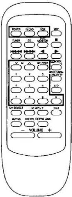 | To watch TV broadcasts with just a TV | ||
| Facing toward the TV TV/DVD → POWER → Power → TV/DVD → TV/DVD → Set the TV/VIDEO mode on the TV to "TV". → Select the desired channel. | |||
| To watch TV broadcasts with a VCR tuner | |||
| Facing toward the TV TV/DVD → POWER → Power → VCR → Power → Switch ON the power for TV. → Switch ON the power for VCR. → Set the TV/VIDEO mode on the TV to "VIDEO". → Facing toward the receiver VCR ↓Facing toward the VCR √CH ∧ or √∅∅∅∅∅∅∅∅∅∅∅∅∅∅∅∅∅∅∅∅∅∅∅∅∅∅∅∅∅∅∅∅∅∅∅∅∅∅∅∅∅∅∅∅∅∅∅∅∅∅∅∅∅∅∅∅∅∅∅∅∅∅∅∅∅∅∅∅∅∅∅∅∅∅∅∅∅∅∅∅∅∅∅∅∅∅∅∅∅∅∅∅∅∅∅∅∅∅∅∅ø∅∅∅∅∅∅∅∅∅∅∅∅∅∅∅∅∅∅∅∅∅∅∅∅∅∅∅∅∅∅∅∅∅∅∅∅∅∅∅∅∅∅∅∅∅∅∅∅∅∅∅∅∅∅∅∅∅∅∅∅∅∅∅∅∅∅∅∅∅∅∅∅∅∅∅∅∅∅∅∅∅∅∅∅∅∅∅∅∅∅∅∅∅∅∅∅∅∅∅○ √CH ∧ or √∅∅∅∅∅∅∅∅∅∅∅∅∅∅∅∅∅∅∅∅∅∅∅∅∅∅∅∅∅∅∅∅∅∅∅∅∅∅∅∅∅∅∅∅∅∅∅∅∅∅∅∅∅∅∅∅∅∅∅∅∅∅∅∅∅∅∅∅∅∅∅∅∅∅∅∅∅∅∅∅∅∅∅∅∅∅∅∅∅∅∅∅○ √CH ∧ or ∖∅∅∅∅∅∅∅∅∅∅∅∅∅∅∅∅∅∅∅∅∅∅∅∅∅∅∅∅∅∅∅∅∅∅∅∅∅∅∅∅∅∅∅∅∅∅∅∅∅∅∅∅∅∅∅∅∅∅∅∅∅∅∅∅∅∅∅∅∅∅∅∅∅∅∅∅∅∅∅∅∅∅∅∅∅∅∅∅∅∅∅∅∅∅∅∅∅∅∅∞ √CH ∧ or ∖∅∅∅∅∅∅∅∅∅∅∅∅∅∅∅∅∅∅∅∅∅∅∅∅∅∅∅∅∅∅∅∅∅∅∅∅∅∅∅∅∅∅∅∅∅∅∅∅∅∅∅∅∅∅∅∅∅∅∅∅∅∅∅∅∅∅∅∅∅∅∅∅∅∅∅∅∅∅∅∅∅∅∅∅∅∅∅∅∅∅∅∅○ √CH ∧ or ∘∅∅∅∅∅∅∅∅∅∅∅∅∅∅∅∅∅∅∅∅∅∅∅∅∅∅∅∅∅∅∅∅∅∅∅∅∅∅∅∅∅∅∅∅∅∅∅∅∅∅∅∅∅∅∅∅∅∅∅∅∅∅∅∅∅∅∅∅∅∅∅∅∅∅∅∅∅∅∅∅∅∅∅∅∅∅∅∅∅∅∅∅∅∅∅∅∅∅∅□ √CH ∧ or ∘∅∅∅∅∅∅∅∅∅∅∅∅∅∅∅∅∅∅∅∅∅∅∅∅∅∅∅∅∅∅∅∅∅∅∅∅∅∅∅∅∅∅∅∅∅∅∅∅∅∅∅∅∅∅∅∅∅∅∅∅∅∅∅∅∅∅∅∅∅∅∅∅∅∅∅∅∅∅∅∅∅∅∅∅∅∅∅∅∅∅∅∅○ √CH ∧ or ∕∅∅∅∅∅∅∅∅∅∅∅∅∅∅∅∅∅∅∅∅∅∅∅∅∅∅∅∅∅∅∅∅∅∅∅∅∅∅∅∅∅∅∅∅∅∅∅∅∅∅∅∅∅∅∅∅∅∅∅∅∅∅∅∅∅∅∅∅∅∅∅∅∅∅∅∅∅∅∅∅∅∅∅∅∅∅∅∅∅∅∅∅∅∅∅∅∅∅○ □ □ □ □ □ □ □ □ □ □ □ □ □ □ □ □ □ □ □ □ □ □ □ □ □ □ □ □ □ □ □ □ □ □ □ □ □ □ □ □ □ □ □ □ □ □ □ □ □ □ ▢ □ □ □ □ □ □ □ □ □ □ □ □ □ □ □ □ □ □ □ □ □ □ □ □ □ □ □ □ □ □ □ □ □ □ □ □ □ □ □ □ □ □ □ □ □ □ □ □ □ △ □ □ □ □ □ □ □ □ □ □ □ □ □ □ □ □ □ □ □ □ □ □ □ □ □ □ □ □ □ □ □ □ □ □ □ □ □ □ □ □ □ □ □ □ □ □ □ □ □ ▩ □ □ □ □ □ □ □ □ □ □ □ □ □ □ □ □ □ □ □ □ □ □ □ □ □ □ □ □ □ □ □ □ □ □ □ □ □ □ □ □ □ □ □ □ □ □ □ □ □ ▲ □ □ □ □ □ □ □ □ □ □ □ □ □ □ □ □ □ □ □ □ □ □ □ □ □ □ □ □ □ □ □ □ □ □ □ □ □ □ □ □ □ □ □ □ □ □ □ □ □ ▨ □ □ □ □ □ □ □ □ □ □ □ □ □ □ □ □ □ □ □ □ □ □ □ □ □ □ □ □ □ □ □ □ □ □ □ □ □ □ □ □ □ □ □ □ □ □ □ □ □ ▦ □ □ □ □ □ □ □ □ □ □ □ □ □ □ □ □ □ □ □ □ □ □ □ □ □ □ □ □ □ □ □ □ □ □ □ □ □ □ □ □ □ □ □ □ □ □ □ □ □ ■ □ □ □ □ □ □ □ □ □ □ □ □ □ □ □ □ □ □ □ □ □ □ □ □ □ □ □ □ □ □ □ □ □ □ □ □ □ □ □ □ □ □ □ □ □ □ □ □ □ ▤ □ □ □ □ □ □ □ □ □ □ □ □ □ □ □ □ □ □ □ □ □ □ □ □ □ □ □ □ □ □ □ □ □ □ □ □ □ □ □ □ □ □ □ □ □ □ □ □ □ ▥ □ □ □ □ □ □ □ □ □ □ □ □ □ □ □ □ □ □ □ □ □ □ □ □ □ □ □ □ □ □ □ □ □ □ □ □ □ □ □ □ □ □ □ □ □ □ □ □ □ ▧ □ □ □ □ □ □ □ □ □ □ □ □ □ □ □ □ □ □ □ □ □ □ □ □ □ □ □ □ □ □ □ □ □ □ □ □ □ □ □ □ □ □ □ □ □ □ □ □ □ ▣ □ □ □ □ □ □ □ □ □ □ □ □ □ □ □ □ □ □ □ □ □ □ □ □ □ □ □ □ □ □ □ □ □ □ □ □ □ □ □ □ □ □ □ □ □ □ □ □ □ ▓ □ □ □ □ □ □ □ □ □ □ □ □ □ □ □ □ □ □ □ □ □ □ □ □ □ □ □ □ □ □ □ □ □ □ □ □ □ □ □ □ □ □ □ □ □ □ □ □ □ ▂ □ □ □ □ □ □ □ □ □ □ □ □ □ □ □ □ □ □ □ □ □ □ □ □ □ □ □ □ □ □ □ □ □ □ □ □ □ □ □ □ □ □ □ □ □ □ □ □ □ ▸ □ □ □ □ □ □ □ □ □ □ □ □ □ □ □ □ □ □ □ □ □ □ □ □ □ □ □ □ □ □ □ □ □ □ □ □ □ □ □ □ □ □ □ □ □ □ □ □ □ ▷ □ □ □ □ □ □ □ □ □ □ □ □ □ □ □ □ □ □ □ □ □ □ □ □ □ □ □ □ □ □ □ □ □ □ □ □ □ □ □ □ □ □ □ □ □ □ □ □ □ ▱ □ □ □ □ □ □ □ □ □ □ □ □ □ □ □ □ □ □ □ □ □ □ □ □ □ □ □ □ □ □ □ □ □ □ □ □ □ □ □ □ □ □ □ □ □ □ □ □ □ ▎ □ □ □ □ □ □ □ □ □ □ □ □ □ □ □ □ □ □ □ □ □ □ □ □ □ □ □ □ □ □ □ □ □ □ □ □ □ □ □ □ □ □ □ □ □ □ □ □ □ ▜ □ □ □ □ □ □ □ □ □ □ □ □ □ □ □ □ □ □ □ □ □ □ □ □ □ □ □ □ □ □ □ □ □ □ □ □ □ □ □ □ □ □ □ □ □ □ □ □ □ ▼ ▚△ ○ ○ ○ ○ ○ ○ ○ ○ ○ ○ ○ ○ ○ ○ ○ ○ ○ ○ ○ ○ ○ ○ ○ ○ ○ ○ ○ ○ ○ ○ ○ ○ ○ ○ ○ ○ ○ ○ ○ ○ ○ ○ ○ ○ ○ ○ ○ ○ ○ ○ ○ ○ ○ ○ ○ ○ ○ ○ ○ ○ ○ ○ ○ ○ ○ ○ ○ ○ ○ ○ ○ ○ ○ ○ ○ ○ ○ ○ ○ ○ ○ ○ ○ ○ ○ ○ ○ ○ ○ ○ ○ ○ ○ ○ ○ ○ ○ ○ ○ ○ ● Each time the button is pressed, the antenna input at the VCR changes from “TV” to “VCR” and vice versa. | |||
| To switch OFF the power to the TV TV/DVD → Power → Power → Power → Power → Power → Power → Power → Power → Power → Power → Power → Power → Power → Power → Power → Power → Power → Power → Power → Power → Power → Power → Power → Power → Power → Power → Power → Power → Power → Power → Power → Power → Power → Power → Power → Power → Power → Power → Power → Power → Power → Power → Power → Power → Power → Power → Power → Power → Power → Power →Power → Power → Power → Power → Power → Power → Power → Power → Power → Power → Power → Power → Power → Power → Power → Power → Power → Power → Power → Power → Power → Power → Power → Power → Power → Power → Power → Power → Power → Power → Power → Power → Power → Power → Power → Power → Power → Power → Power → Power → Power → Power → Power → Power → Power → Power → Power → Power → Power → Power → Other | |||
To watch video tapes
The procedures below are examples for when a TV and VCR are connected as shown on page 8.
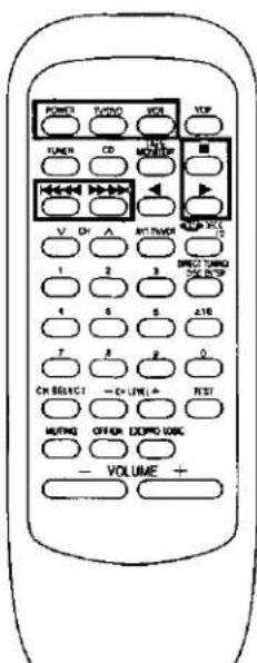 | Facing toward the TV TV/DVD → POWER → Switch ON the power for TV. | Facing toward the VCR vCR → POWER → Switch ON the power for VCR. | Set the TV/VIDEO mode on the TV to “VIDEO”. | Facing toward the receiver VCR ↓ Facing toward the VCR ↓ Playback will begin. | |
| To fast-forward or rewind the video tape | In the stop mode VCR ↔ ↔ ↔ ↗ ↗ ↗ ↗ ↗ ↗ ↗ ↗ ↗ ↗ ↗ ↗ ↗ ↗ ↗ ↗ ↗ ↗ ↗ ↗ ↗ ↗ ↗ ↗ ↗ ↗ ↗ ↗ ↗ ↗ ↗ ↗ ↗ ↗ ↗ ↗ ↗ ↗ ↗ ↗ ↗ ↗ ↗ ↗ ↗ ↗ ↗ ↗ ↗ ↗ ↘ | ||||
| To stop playback | VCR ▪ ↗ ↗ ↗ ↗ ↗ ↗ ↗ ↗ ↗ ↗ ↗ ↗ ↗ ↗ ↗ ↗ ↗ ↗ ↗ ↗ ↗ ↗ ↗ ↗ ↗ ↗ ↗ ↗ ↗ ↗ ↗ ↗ ↗ ↗ ↗ ↗ ↗ ↗ ↗ ↗ ↗ ↗ ↗ ↗ ↗ ↗ ↗ ↗ ↗ ↕ | ||||
| To switch OFF the power to the TV | TV/DVD → POWER ↗ ↗ ↗ ↗ ↗ ↗ ↗ ↗ ↗ ↗ ↗ ↗ ↗ ↗ ↗ ↗ ↗ ↗ ↗ ↗ ↗ ↗ ↗ ↗ ↗ ↗ ↗ ↗ ↗ ↗ ↗ ↗ ↗ ↗ ↗ ↗ ↗ ↗ ↗ ↗ ↗ ↗ ↗ ↗ ↗ ↗ ↗ ↗ ↗ ↓ | ||||
| To switch OFF the power to the VCR | VCR → POWER ↗ ↗ ↗ ↗ ↗ ↗ ↗ ↗ ↗ ↗ ↗ ↗ ↗ ↗ ↗ ↗ ↗ ↗ ↗ ↗ ↗ ↗ ↗ ↗ ↗ ↗ ↗ ↗ ↗ ↗ ↗ ↗ ↗ ↗ ↗ ↗ ↗ ↗ ↗ ↗ ↗ ↗ ↗ ↗ ↗ ↗ ↗ ↗ ↘ | ||||
Note
Some TVs and VCRs cannot be operated with this remote control.
Troubleshooting guide
Before requesting service for this unit, check the chart below for a possible cause of the problem you are experiencing. Some simple checks or a minor adjustment on your part may eliminate the problem and restore proper operation.
If you are in doubt about some of the check points, or if the remedies indicated in the chart do not solve the problem, refer to the directory of Authorized Service Centers (enclosed with this unit) to locate a convenient service center, or consult your Technics dealer for instructions.
(In U.S.A. consult PASC Authorized Servicenters for detailed instructions or call 1-800-545-2672 for the address of an authorized factory servicenter.)
Reference pages indicated in black circles. (For example: ⑨)
| Problem | Probable cause(s) | Suggested remedy |
| While listening to FM broadcasts | ||
| An unusual hissing noise is heard when listening to the broadcast in stereo, but not heard when listening monaurally. | A slight noise may be heard because the method used for modulation of FM stereo broadcasts is different than that used for monaural broadcasts. | Try reducing the treble sound by using the treble control.(12)Try changing the location, height and/or direction of the antenna.(9 10)If an indoor antenna is being used, change to an outdoor antenna.(10)Try using an antenna with more elements. |
| Noise is excessive in both stereo and monaural broadcasts. | Poor location and/or direction of the antenna. | |
| Transmitting station is too far away. | ||
| The FM stereo indicator or the quartz lock indicator flickers, without completely illuminating. | Poor location and/or direction of the antenna. | Try changing the location, height and/or direction of the antenna.(9 10)If an indoor antenna is being used, change to an outdoor antenna.(10)Try using an antenna with more elements. |
| Transmitting station is too far away. | ||
| Excessive distortion in the sound of stereo broadcasts. | Nearby building or mountain. | |
| While listening to AM broadcasts | ||
| An unusual “beat” sound is heard. | Unit is being used at the same time as the television set. | • Turn off the television set, or use this unit farther away from it. |
| Interference from adjacent broadcast signal. | • Try reducing the treble sound by using the treble control. (15) | |
| A low-pitched “hum” sound is heard when the station is tuned. | The AM loop antenna connection wires are too close to the power cord. | • Place the antenna connection wires and the power cord farther apart. |
| The power supply frequency from the power cord is modulated and heard from the speakers. | • Install a special outdoor antenna. (16) | |
| A strange hissing noise is produced continuously or intermittently. | Caused by the “discharge phenomenon” and the “oscillation phenomenon” of electric appliances (such as fluorescent lights, TV, small series-type motors, rectification equipment, etc.). | • Try placing this unit farther away from such equipment. |
| Common Problems | ||
| Power will not switch ON. | The power cord plug is not completely inserted. | Confirm that the power cord plug is connected completely. |
| No sound is heard. | The speaker indicator is turned off. | Turn on the speaker indicator. (18) |
| The tape monitor function is ON. | Press the tape monitor button. (19) | |
| The muting function is ON. | Press the muting button. (10) | |
| Connections are incomplete or incorrect to the speaker systems, etc. | Check that all connection wires are correctly connected. (11 12) | |
| The incorrect input selector has been pressed. | Check that the correct selector is pressed. (13) | |
| Sound stops during a performance, or no sound is heard when the power is switched ON.(The word “OVERLOAD” appears on the display.) | The protection circuitry has functioned because the positive and negative speaker connection wires have “shorted,” speaker systems with an impedance less than the indicated rated impedance of this unit have been used or under severe use, such excessive volume, excessive power and in an excessively hot environment. | Switch off the power, and after determining and correcting the cause, switch on the power once again.Use a speaker system of the proper impedance rating. (11 12) |
■ AMPLIFIER SECTION
Rated minimum sine wave RMS power output 40 Hz-20 kHz both channels driven 0.8% total harmonic distortion
80 W per channel (8 Ω)
1 kHz continuous power output both channels driven
0.05% total harmonic distortion 83 W per channel (8 Ω)
Total harmonic distortion
rated power at 40 Hz–20 kHz 0.8% (8 Ω)
half power at 1 kHz 0.07% (8 Ω)
Power output at the Dolby Pro Logic operation
| 0.9% at 1 kHz, | |
| Front | 2×80 W (8 Ω) |
| Center | 80 W (8 Ω) |
| Surround | 80 W (8 Ω) |
Low frequency damping factor
Load impedance
| Front | 8 Ω |
| Center | 8 Ω |
| Surround | 4-8 Ω |
Frequency response
PHONO RIAA standard curve ±0.8 dB
CD, TAPE MONITOR, TV/DVD/DSS, VCR 10 Hz-70 kHz, ±3 dB
Input sensitivity
PHONO 0.4 mV (3 mV, IHF' 66)
| CD, TAPE MONITOR, TV/DVD/DSS, VCR |
| 27 mV (200 mV, IHF' 66) |
S/N (IHF A)
PHONO 70 dB (78 dB, IHF' 66)
CD, TAPE MONITOR, TV/DVD/DSS, VCR
75 dB (83 dB, IHF' 66)
Input impedance
PHONO 47 kΩ
CD, TAPE MONITOR, TV/DVD/DSS, VCR 22 kΩ
Tone controls
BASS 50 Hz, +10 to -10 dB
TREBLE 20 kHz, +10 to -10 dB
Subwoofer frequency response
7 Hz-100 Hz, ±3 dB
■ FM TUNER SECTION
| Frequency range | 87.9~107.9 MHz |
| Sensitivity | 11.2 dBf (2 μV, IHF '58) |
| 50 dB quieting sensitivity | |
| MONO | 18.3 dBf (4.5 μV, IHF '58) |
| STEREO | 38.3 dBf (45 μV, IHF '58) |
| Total harmonic distortion | |
| MONO | 0.2% |
| STEREO | 0.3% |
| S/N | |
| MONO | 73 dB |
| STEREO | 67 dB |
| Frequency response | 20 Hz-15 kHz, +1 dB, -2 dB |
| Alternate channel selectivity | 65 dB |
| Capture ratio | 1.5 dB |
| Image rejection at 98 MHz | 40 dB |
| Spurious response rejection at 98 MHz | 75 dB |
| AM suppression | 50 dB |
| Stereo separation | |
| 1 kHz | 40 dB |
| 10 kHz | 30 dB |
| Antenna terminal | 75 Ω (unbalanced) |
■ AM TUNER SECTION
| Frequency range | 530–1710 kHz |
| Sensitivity | 20 μV, 330 μV/m |
| Selectivity | 55 dB |
| IF rejection at 1000 kHz | 50 dB |
VIDEO SECTION
| Output voltage at 1 V input (unbalanced) | 1 ± 0.1 Vp-p |
| Maximum input voltage | 1.5 Vp-p |
| Input/output impedance | 75 Ω |
GENERAL
| Power supply | AC 120 V, 60 Hz |
| Power consumption | 185 W(In standby condition: 2 W) |
| Dimensions (W×H×D) | 430×136×309 mm(16-15/16"×5-11/32"×12-5/32") |
| Weight | 7.5 kg (16.5 lb.) |
Notes:
- Specifications are subject to change without notice. Weight and dimensions are approximate.
- Total harmonic distortion is measured by the digital spectrum analyzer.
Product service
Do not attempt to remove the cover(s) or repair the unit yourself.
Refer servicing to qualified personnel only.
Product information
For product service, product information or assistance in product operation, refer to the servicenter directory.
Panasonic Consumer Electronics
Company, Division of Matsushita
Electric Corporation of America
One Panasonic Way Secaucus,
New Jersey 07094
Panasonic Sales Company,
Division of Matsushita Electric of
Puerto Rico, Inc. ("PSC")
Ave. 65 de Infantería. Km. 9.5
San Gabriel Industrial Park, Carolina,
Puerto Rico 00985
Panasonic Canada Inc.
5770 Ambler Drive,
Mississauga, Ontario
L4W 2T3

RQT4166-P
H1097V0
- AV Control Stereo Receiver
- SA-EX320
- Technics®
- Dear Customer
- Table of contents
- CAUTION
- THIS PHRASE IS APPLIED ONLY FOR U.S.A.
- CAUTION:
- WARNING:
- Precautions
- Safety
- Installation
- Environment
- Placement
- Maintenance
- Service
- Supplied accessories
- Listening caution
- Concerning the remote control
- Battery installation
- When you need to replace these batteries
- Method for use
- Note
- Front panel controls
- Connecting audio equipment
- Connecting video equipment
- Antenna connections
- FM indoor antenna (included)
- AM loop antenna (included)
- When mounting the antenna to a column, a wall or rack C
- FM outdoor antenna (not included)
- AM outdoor antenna (not included)
- Placement of speakers
- Connecting speakers
- Front speakers
- Center speaker and Surround speakers
- Speaker impedance:
- Subwoofer
- To connect a subwoofer which does not have a built-in amplifier
- Connecting the speaker cable
- Basic operations
- After listening is finished
- When the tape monitor indicator is lit or flashing A
- To adjust the tone quality
- To adjust the sound balance
- To mute the sound level
- Press MUTING.
- To listen through headphones
- Listening to radio broadcasts
- Sequential tuning
- Direct tuning
- Preset tuning
- Please remember this
- Automatic memory presetting
- When FM stations are preset,
- When FM and AM stations are preset,
- When a broadcast station is preset A
- When presetting is completed
- Manual memory presetting
- Set to the desired frequency.
- Press MEMORY.
- Press PRESET (∨) or (∧) to select the desired channel.
- To continue presetting
- To listen to preset channels
- To confirm the channel number of the broadcast station being received
- For your reference
- If frequency presettings are accidentally erased
- Enjoying sound with DOLBY PRO LOGIC
- SURROUND A
- STEREO B
- Setting the center mode and adjusting speaker output level
- NORMAL
- by remote control only
- by remote control
- To stop the test signal
- To turn off the Dolby Pro Logic systems
- Enjoying SURROUND or 3 STEREO
- Making a recording
- Recording on a tape deck
- Recording on a VCR
- About the HELP function
- Press -HELP.
- Remote control operation
- Troubleshooting guide
- ■ AMPLIFIER SECTION
- Rated minimum sine wave RMS power output 40 Hz-20 kHz both channels driven 0.8% total harmonic distortion
- Notes:
- Product service
- Product information
Marque : TECHNICS
Modèle : SA-EX320
Catégorie : Recepteur