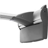
WMAC16 - Accessoire de projecteur Chief - Notice d'utilisation et mode d'emploi gratuit
Retrouvez gratuitement la notice de l'appareil WMAC16 Chief au format PDF.


| Type de produit | Support mural pour projecteur |
| Marque | Chief |
| Modèle | WMAC16 |
| Compatibilité | Projecteurs compatibles avec le système de montage Chief, jusqu'à 16 kg |
| Capacité de charge maximale | 16 kg |
| Dimensions (L x H x P) | Environ 30 x 20 x 10 cm |
| Poids net | Environ 2 kg |
| Matériau | Acier robuste avec finition noire |
| Couleur | Noir |
| Fonctions principales | Fixation murale sécurisée, inclinaison et rotation réglables, gestion des câbles intégrée |
| Installation | Fixation murale avec vis et chevilles fournies ; nécessite un niveau à bulle |
| Sécurité | Verrouillage de sécurité intégré ; utilisation de vis de blocage |
| Entretien et nettoyage | Nettoyer avec un chiffon doux sec ; éviter les produits abrasifs |
| Pièces détachées et réparabilité | Pièces de rechange disponibles via Chief ; réparation par un professionnel recommandée |
| Garantie | Garantie limitée de 5 ans |
FOIRE AUX QUESTIONS - WMAC16 Chief
Questions des utilisateurs sur WMAC16 Chief
0 question sur cet appareil. Repondez a celles que vous connaissez ou posez la votre.
Poser une nouvelle question sur cet appareil
Téléchargez la notice de votre Accessoire de projecteur au format PDF gratuitement ! Retrouvez votre notice WMAC16 - Chief et reprennez votre appareil électronique en main. Sur cette page sont publiés tous les documents nécessaires à l'utilisation de votre appareil WMAC16 de la marque Chief.
MODE D'EMPLOI WMAC16 Chief
INSTALLATION INSTRUCTIONS

Short Throw Wall Plate
DISCLAIMER
Milestone AV Technologies and its affiliated corporations and subsidiaries (collectively "Milestone"), intend to make this manual accurate and complete. However, Milestone makes no claim that the information contained herein covers all details, conditions or variations, nor does it provide for every possible contingency in connection with the installation or use of this product. The information contained in this document is subject to change without notice or obligation of any kind. Milestone makes no representation of warranty, expressed or implied, regarding the information contained herein. Milestone assumes no responsibility for accuracy, completeness or sufficiency of the information contained in this document.
Chief® is a registered trademark of Milestone AV Technologies. All rights reserved.

CAUTION: A CAUTION alerts you to the possibility of damage or destruction of equipment if you do not follow the corresponding instructions.

WARNING: Failure to read, thoroughly understand, and follow all instructions can result in serious personal injury, damage to equipment, or voiding of factory warranty! It is the installer's responsibility to make sure all components are properly assembled and installed using the instructions provided.

IMPORTANT WARNINGS AND
CAUTIONS!

WARNING: A WARNING alerts you to the possibility of serious injury or death if you do not follow the instructions.
DIMENSIONS
![[33.3] 1.31 MIN DISTANCE FROM INSIDE OF COVER TO WALL [413.7] 16.29 [206.9] 8.14 [10.8] 3X 0.43 [48.1] 3X 1.89 [65.6] 2.58 MAX DISTANCE FROM INSIDE OF COVER TO WALL [470.9] 18.54 [272.9] 10.75 [508.1] 20.00 [15.9] 0.63 [68.9] 2.71](/content/2026/06/1309372/images/9767c84c65c482f23090d719ae87f1053d9ec7b06f20a47d885ca40185e12855.jpg)
TOOLS / PARTS FOR INSTALLATION
![A (1) [wall plate]](/content/2026/06/1309372/images/5cf11e7e3402016a15b67876de6c0df15070eed51614827940968ee531227079.jpg)
ASSEMBLY AND INSTALLATION
NOTE: The WMAC16 short throw wall plate can be used on any length dual stud short throw wall mount (WM2 Series).
- Remove endcaps from short throw mount by removing four Phillips pan head sheet metal screws. (See Figure 1)

Figure 1
- Loosely attach short throw wall plate (A) to short throw wall mount using two of the Phillips pan head sheet metal screws removed in Step 1. (See Figure 2)
IMPORTANT ! : Only partially tighten screws so that cover may be lifted forward to manage cables in next step.
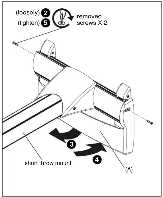
Figure 2
- Lift short throw wall plate (A) forward and organize cables underneath it as desired. (See Figure 2)
- Slide short throw wall plate (A) back against wall. (See Figure 2)
- Tighten two screws to secure wall plate to mount. (See Figure 2)
Marque : Chief
Modèle : WMAC16
Catégorie : Accessoire de projecteur