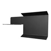
SMA620 - Accessoire de projecteur Chief - Notice d'utilisation et mode d'emploi gratuit
Retrouvez gratuitement la notice de l'appareil SMA620 Chief au format PDF.


| Type de produit | Support de projecteur |
| Marque | Chief |
| Modèle | SMA620 |
| Dimensions (L x l x h) | 30 cm x 20 cm x 10 cm |
| Poids | 2,5 kg |
| Alimentation | Non applicable |
| Capacité de charge maximale | 20 kg |
| Matériau | Acier |
| Couleur | Noir |
| Fonctions principales | Montage mural, ajustement d'inclinaison et de rotation |
| Angle d'inclinaison | +15° / -15° |
| Angle de rotation | 360° |
| Distance au mur | 10 cm |
| Type de montage | Mur |
| Compatibilité VESA | Oui (standard 75x75 mm à 200x200 mm) |
| Instructions d'entretien | Nettoyer avec un chiffon doux et sec |
| Consignes de sécurité | Vérifier régulièrement la fixation murale et ne pas dépasser la charge maximale |
| Contenu de l'emballage | Support, vis, chevilles, notice d'installation |
| Garantie | 2 ans |
| Réparabilité | Pièces détachées disponibles sur demande |
FOIRE AUX QUESTIONS - SMA620 Chief
Questions des utilisateurs sur SMA620 Chief
0 question sur cet appareil. Repondez a celles que vous connaissez ou posez la votre.
Poser une nouvelle question sur cet appareil
Téléchargez la notice de votre Accessoire de projecteur au format PDF gratuitement ! Retrouvez votre notice SMA620 - Chief et reprennez votre appareil électronique en main. Sur cette page sont publiés tous les documents nécessaires à l'utilisation de votre appareil SMA620 de la marque Chief.
MODE D'EMPLOI SMA620 Chief
The SMA-620 suspended ceiling track clip allows you to secure ceiling grid to the Smart-Lift SL-236 for suspended ceiling applications.
Unpack carton and check contents:
(8) Suspended Ceiling Track Clip
INSTALLATION INSTRUCTIONS
- Determine where the ceiling grid will intersect with the Smart-Lift (see Figure 1).
- Remove surrounding ceiling tile.
- Cut ceiling grid to appropriate length and trim end to fit into Smart-Lift.
- Install the ceiling track clip, with the slot of the clip directly in line with the intersection point, into the Smart-Lift as shown in Figure 2.
- Insert the grid into ceiling track clip (see Figure 3).
- Cut surrounding ceiling tile to appropriate size.
- Repeat previous steps as necessary.
- Replace surrounding ceiling tile.

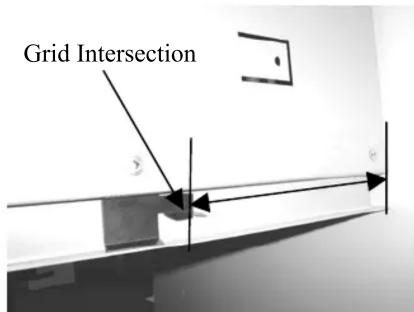

Figure 1. Grid Intersection Figure 2. Clip Installation Figure 2. Grid Installation
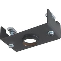
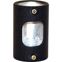
Marque : Chief
Modèle : SMA620
Catégorie : Accessoire de projecteur