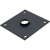
CMA110-G - Accessoire de projecteur Chief - Notice d'utilisation et mode d'emploi gratuit
Retrouvez gratuitement la notice de l'appareil CMA110-G Chief au format PDF.


| Type de produit | Support de projecteur |
| Marque | Chief |
| Modèle | CMA110-G |
| Dimensions approximatives | 20 x 20 x 10 cm |
| Poids approximatif | 1,5 kg |
| Alimentation | Aucune (dispositif passif) |
| Capacité de charge maximale | 15 kg |
| Matériau principal | Acier renforcé |
| Fonctions principales | Montage au plafond ou au mur, réglage d'inclinaison (jusqu'à 15°), pivotement (360°), et rotation |
| Compatibilité | Universelle avec la plupart des projecteurs (point de fixation standard) |
| Installation | Fixation au plafond ou au mur avec vis fournies, support projecteur amovible |
| Entretien et nettoyage | Nettoyer avec un chiffon doux et sec ; ne pas utiliser de produits chimiques |
| Sécurité | Vérifier régulièrement la fixation et la charge ; ne pas dépasser la capacité maximale |
| Pièces détachées et réparabilité | Kit de montage complet fourni ; vis de rechange disponibles auprès du fabricant |
| Informations générales | Garantie du fabricant incluse ; conçu par Chief, leader en solutions de montage |
FOIRE AUX QUESTIONS - CMA110-G Chief
Questions des utilisateurs sur CMA110-G Chief
0 question sur cet appareil. Repondez a celles que vous connaissez ou posez la votre.
Poser une nouvelle question sur cet appareil
Téléchargez la notice de votre Accessoire de projecteur au format PDF gratuitement ! Retrouvez votre notice CMA110-G - Chief et reprennez votre appareil électronique en main. Sur cette page sont publiés tous les documents nécessaires à l'utilisation de votre appareil CMA110-G de la marque Chief.
MODE D'EMPLOI CMA110-G Chief
INSTALLATION INSTRUCTIONS

Ceiling Plates
DISCLAIMER
Milestone AV Technologies and its affiliated corporations and subsidiaries (collectively "Milestone"), intend to make this manual accurate and complete. However, Milestone makes no claim that the information contained herein covers all details, conditions or variations, nor does it provide for every possible contingency in connection with the installation or use of this product. The information contained in this document is subject to change without notice or obligation of any kind. Milestone makes no representation of warranty, expressed or implied, regarding the information contained herein. Milestone assumes no responsibility for accuracy, completeness or sufficiency of the information contained in this document.
Chief® is a registered trademark of Milestone AV Technologies. All rights reserved.

IMPORTANT SAFETY INSTRUCTIONS!

WARNING: A WARNING alerts you to the possibility of serious injury or death if you do not follow the instructions.

CAUTION: A CAUTION alerts you to the possibility of damage or destruction of equipment if you do not follow the corresponding instructions.

WARNING: Failure to read, thoroughly understand, and follow all instructions can result in serious personal injury, damage to equipment, or voiding of factory warranty! It is the installer's responsibility to make sure all components are properly assembled and installed using the instructions provided.

WARNING: Failure to provide adequate structural strength for this component can result in serious personal injury or damage to equipment! It is the installer's responsibility to make sure the structure to which this component is attached can support five times the combined weight of all equipment. Reinforce the structure as required before installing the component.

WARNING: Exceeding the weight capacity can result in serious personal injury or damage to equipment! It is the installer's responsibility to make sure the combined weight of all components attached to the CMA mount does not exceed 500 lbs (226.8 kg).
NOTE: The weight capacity of the CMA mounts may be LIMITED to the lowest weight capacity of any other component located between the ceiling plate and the projector/display.

WARNING: Use this mounting system only for its intended use as described in these instructions. Do not use attachments not recommended by the manufacturer.

WARNING: Never operate this mounting system if it is damaged. Return the mounting system to a service center for examination and repair.

WARNING: Do not use this product outdoors.
NOTE: CMA105, CMA110, CMA115 are intended to be used with a 1-1/2" NPT or NPSM following ANSI/ASME B1.20.1 (Schedule 40, 0.154" minimum thickness aluminum - ASTM B221) threaded extension column (not included).
IMPORTANT ! : These CMA mounts are designed to be:
- mounted to a 2" x 6" wood framework ceiling covered with 5/8" drywall;
- mounted to an 8" concrete ceiling using either 1/4" x 2-1/2" lag bolts for Togger AF8 anchors (not included), or 5/16" x 2-1/2" lag bolts for Fischer UX10 concrete anchors (not included);
- suspended from four 3/8" diameter (minimum) Grade 2 or better threaded rods with 16 threads per inch (not included) which are secured to a framing channel (spanning a maximum of 5 feet --not included) by Grade 2 or better 3/8" channel nuts (not included).
NOTE: These CMA mounts provide vertical adjustments in 3/4" increments.
NOTE: CMA105, CMA110 and CMA115 may be used with UL Listed CMA151 1-1/2" to 1" NPT Adapter Accessory.

WARNING: Do NOT attach to vertical mounting surfaces such as walls or angled ceilings!
--SAVE THESE INSTRUCTIONS--
DIMENSIONS
![CMA105 [101.800] 4.00 [59.356] 2.935 [34.183] 1.35 [38.100] 1.55 [76.200] 3.00 1 1/2 NPT [101.600] 4.86 4X .44 X .75 SLO1 [11.2 X 19.0] [17.254] .88 DIMENSIONS: INCHES [MILLIMETERS]](/content/2026/06/1309369/images/604d67a87c812db72651ac7b992fe6067823147954b043a030169ecd694d5857.jpg)
![CMA110 [203.200] 8.00 [157.226] 6.19 [78.437] 3.00 [22.087] .81 [19.050] .75 [82.550] 3.25 [185.100] 6.30 1 1/2 NPT [203.200] 8.00 4X .44 X .75 SLO1 [11.2 X 19.0] [17.254] .68 DIMENSIONS: INCHES [MILLIMETERS]](/content/2026/06/1309369/images/dfd995bbfc4323a72027946694829f42a781118e19ee4eaf9fd8470b027e41db.jpg)
DIMENSIONS (continued)
![CMA115 [105,426] 4.19 [53,213] 2.10 [22,387] .91 [19,650] .75 [57,150] 2.25 [114,330] 4.50 [152,400] 6.00 1 1/2 NPT [152,400] 5.00 4X .44 X .75 SLOT [11.2 X 19.0] DIMENSIONS: INCHES [MILLIMETERS]](/content/2026/06/1309369/images/dae17c8fa3002b62ca94ace49816aa0d94edd40d64db4497bf00ea2625992a67.jpg)
TOOLS REQUIRED FOR INSTALLATION

PARTS
![A (1) [ceiling plate - CMA105 shown] B (1) #10-24 x 1/4" C (1) #10-24 x 1/4" D (1) [security spinner] E (1) 5/32" (security) F (1) 3/32"](/content/2026/06/1309369/images/99e73db2f55c07060fcfe82bc24f5edd412edc26900d45f88d816f3c4703432f.jpg)
LEGEND
 | Tighten Fastener |
| Apretar elemento de fijación | |
| Befestigungsteil festziehen | |
| Apertar fixador | |
| Serrare il fissaggio | |
| Bevestiging vastdraaien | |
| Serrez les fixations | |
 | Loosen Fastener |
| Aflojar elemento de fijación | |
| Befestigungsteil lösen | |
| Desapertar fixador | |
| Allentare il fissaggio | |
| Bevestiging losdraaien | |
| Desserrez les fixations | |
 | Phillips Screwdriver |
| Destornillador Phillips | |
| Kreuzschlitzschraubendreher | |
| Chave de fendas Phillips | |
| Cacciavite a stella | |
| Kruiskopschroevendraaier | |
| Tournevis à pointe cruciforme | |
 | Open-Ended Wrench |
| Llave de boca | |
| Gabelschlüssel | |
| Chave de bocas | |
| Chiave a punte aperte | |
| Steeksleutel | |
| Clé à fourche | |
 | By Hand |
| A mano | |
| Von Hand | |
| Com a mão | |
| A mano | |
| Met de hand | |
| À la main | |
 | Hex-Head Wrench |
| Llave de cabeza hexagonal | |
| Sechskantschlüssel | |
| Chave de cabeça sextavada | |
| Chiave esagonale | |
| Zeskantsleutel | |
| Clé à tête hexagonale |





INSTALLATION AND ASSEMBLY

WARNING: Do NOT attach to vertical mounting surfaces such as walls or angled ceilings!

WARNING: IMPROPER INSTALLATION CAN LEAD TO LIFT FALLING CAUSING SEVERE PERSONAL INJURY OR DAMAGE TO EQUIPMENT! It is the installer's responsibility to make certain the structure to which the mount is being attached is capable of supporting five times the weight of the CMA mount and all attached equipment. Reinforce the structure as required before installing the mount.
NOTE: The following instructions assume a suitable mounting structure and surface exists prior to installation.
Installing to a Wood Framework (Joists)
NOTE: These CMA mounts are designed to be mounted to a 2" x 6" wood framework ceiling covered with 5/8" drywall.
- Use 5/16-18" x 2-1/2" (minimum) Grade 2 lag screws (not included) to secure CMA mount to the joists or wood framework, using the bolt holes noted. (See Figure 1)
NOTE: If using only two bolt holes for mounting, two opposing holes must be used.
Installing to a Suspended Ceiling
NOTE: These CMA mounts may be suspended from four 3/8" diameter (minimum) Grade 2 or better threaded rods
with 16 threads per inch (not included) which are secured to a framing channel (spanning a maximum of 5 feet--not included) by Grade 2 or better 3/8" channel nuts (not included).
- Insert the rods into the four bolt holes in the CMA mount. (See Figure 1)
- Secure the threaded rods to the CMA mount with Grade 2 or better 3/8" jam nuts (not included) and washers (one of each on inside and one of each on outside--not provided).
Installing to a Solid Concrete Ceiling Structure
NOTE: These CMA mounts may be mounted to an 8" concrete ceiling using either 1/4" x 2-1/2" lag bolts for Togger AF8 anchors (not included), or 5/16" x 2-1/2" lag bolts for Fischer UX10 concrete anchors (not included)

WARNING: Anchors (not included) must be installed into structurally sound solid concrete. Installation into hollow concrete block, mortar, or concrete that exhibits cracking, spalling, or other defects may result in failure of anchor and serious personal injury or damage to equipment.
- Use either 1/4" x 2-1/2" lag bolts for Togger AF8 anchors (not included), or 5/16" x 2-1/2" lag bolts for Fischer UX10 concrete anchors (not included) to secure CMA mount into solid concrete ceiling. (See Figure 1)
- Place CMA mount over anchors, placing bolt holes in CMA mount over anchors.
- Secure CMA mount to ceiling using four Grade 2 flat washers (not included) and four Grade 2 nuts (not included) tightened over anchors.
![[101.600] 4.00 [68.326] 2.980 [34.163] 1.35 [39.100] 1.50 [74.200] 3.00 [101.600] 4.00 1 1/2 NF* 4X 44 X .75 SLOT [11.2 X 18.5]](/content/2026/06/1309369/images/535a604ee9fd4e277523153cac790dd7c52aa09aa014fc52845612ee28f43a4f.jpg)
CMA105
![[159.400] 6.00 [105.425] 4.19 [50.213] 2.10 [22.967] 81 [19.050] .75 [57.150] 2.25 [114.300] 8.26 1 ½ NPI [162.400] 6.00 4X 44 X 75 8.0T [11 2 X 10.0]](/content/2026/06/1309369/images/7e027e8a2d92294ea07a8cd86025910e81f9b681c21cf6175da3a5315091429c.jpg)
CMA115
![[203.200] 8.00 [157.206] 6.15 [78.457] 3.89 [22.897] 51 [19.056] .75 (82.550) 3.20 [165.100] 5.50 230.200 8.00 1 1/2 9/7 4X 44 X 75 8.01 [1.2 X 19.0]](/content/2026/06/1309369/images/2c5f7ce89b8add1b71b651059defac02c4c9f400248a65b56485628de58de31b.jpg)
CMA110
Figure 1
Attaching Column to CMA Mount (non-security)
- Install 1-1/2" NPT or NPSM following ANSI/ASME B1.20.1 (Schedule 40, 0.154" minimum thickness steel or aluminum - ASTM B221) threaded extension column (not included) into threaded collar until tight, with a minimum of four threads engaged. (See Figure 2)
- Install #10-24 1/4" set screw (B) into hole on ceiling plate (A) to secure pipe to mount. (See Figure 2)
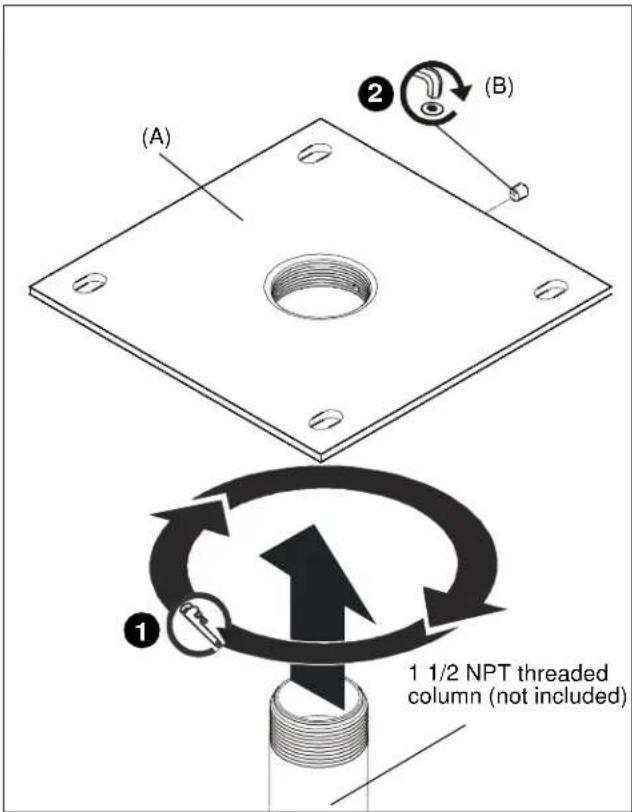
Figure 2
- Install the ceiling mount and projector to the CMA mount using installation instructions included with the ceiling mount.
Attaching Column to CMA Mount (security)
- Install 1-1/2" NPT or NPSM following ANSI/ASME B1.20.1 (Schedule 40, 0.154" minimum thickness steel or aluminum - ASTM B221) threaded extension column (not included) into threaded collar until tight, with a minimum of four threads engaged. (See Figure 3)
- Install #10-24 1/4" button head security screw (C) through security spinner (D) and into hole on ceiling plate (A) to secure pipe to mount. (See Figure 3)

Figure 3
- Install the ceiling mount and projector to the CMA mount using installation instructions included with the ceiling mount.
CMA105-110-115
Installation Instructions
- INSTALLATION INSTRUCTIONS
- DISCLAIMER
- IMPORTANT SAFETY INSTRUCTIONS
- INSTALLATION AND ASSEMBLY
- INSTALLING TO A WOOD FRAMEWORK (JOISTS)
- INSTALLING TO A SUSPENDED CEILING
- INSTALLING TO A SOLID CONCRETE CEILING STRUCTURE
- ATTACHING COLUMN TO CMA MOUNT (NON-SECURITY)
- ATTACHING COLUMN TO CMA MOUNT (SECURITY)
Marque : Chief
Modèle : CMA110-G
Catégorie : Accessoire de projecteur