
DSP-A700 - Système Hi-Fi YAMAHA - Notice d'utilisation et mode d'emploi gratuit
Retrouvez gratuitement la notice de l'appareil DSP-A700 YAMAHA au format PDF.


| Type de produit | Amplificateur numérique avec processeur DSP |
| Marque | Yamaha |
| Modèle | DSP-A700 |
| Puissance de sortie | 70 W par canal (8 ohms, 20 Hz - 20 kHz) |
| Nombre de canaux | 5 canaux (avant, central, surround) |
| Réponse en fréquence | 20 Hz - 20 kHz (+/- 0.5 dB) |
| Distorsion harmonique totale | < 0.05 % |
| Rapport signal/bruit | > 95 dB |
| Entrées audio | 6 entrées ligne (CD, tuner, tape, etc.) |
| Sorties audio | 2 sorties enregistreur, 1 sortie caisson de basses |
| Modes DSP | Hall, Église, Stade, Jazz, Rock, etc. |
| Télécommande | Oui, infrarouge |
| Alimentation | 220-240 V, 50/60 Hz |
| Consommation électrique | 350 W (max) |
| Dimensions (L x H x P) | 435 x 151 x 392 mm |
| Poids | 12,5 kg |
| Entretien et nettoyage | Dépoussiérer avec un chiffon doux et sec. Éviter les solvants. |
| Sécurité | Ne pas exposer à l'humidité. Débrancher avant nettoyage. |
| Pièces détachées et réparabilité | Contacter un centre de service agréé Yamaha. |
| Informations générales | Notice d'utilisation disponible en téléchargement gratuit. |
FOIRE AUX QUESTIONS - DSP-A700 YAMAHA
Questions des utilisateurs sur DSP-A700 YAMAHA
0 question sur cet appareil. Repondez a celles que vous connaissez ou posez la votre.
Poser une nouvelle question sur cet appareil
Téléchargez la notice de votre Système Hi-Fi au format PDF gratuitement ! Retrouvez votre notice DSP-A700 - YAMAHA et reprennez votre appareil électronique en main. Sur cette page sont publiés tous les documents nécessaires à l'utilisation de votre appareil DSP-A700 de la marque YAMAHA.
MODE D'EMPLOI DSP-A700 YAMAHA
YAMAHA
DIGITAL SOUND FIELD PROCESSOR OPERATION MANUAL
DSP-A700/E300
Congratulations!
You are the proud owner of a Yamaha Digital Sound Field Processing (DSP) System—an extremely sophisticated audio component. The DSP system takes full advantage of Yamaha's undisputed leadership in the field of digital audio processing to bring you a whole new world of listening experiences. Follow the instructions in this manual carefully when setting up your system, and the DSP system will sonically transform your room into a wide range of listening environments—anything from a famous concert hall to a cozy jazz club. In addition, you get incredible realism from Dolby-encoded video tapes using the built-in Dolby Pro Logic Surround Decoder.
Seven built-in channels of amplification on the DSP-A700 mean that no additional amplifiers are required to enjoy advanced digital sound field processing. The DSP-E300 with five channels of amplification is useful when adding to an existing system containing an amplifier or receiver. You may use any available speakers with your system, but Yamaha Active Servo Technology Speakers are especially recommended for stunning realism and impact.
Rather than tell you about the wonders of digital sound field processing, however, let's get right down to the business of setting up the system and trying out its many capabilities. Please read this operation manual carefully and store it in a safe place for later reference.
How to Use This Manual
This manual describes two Yamaha digital sound field processing systems, the DSP-A700 and the DSP-E300. The principle difference between these two is that the DSP-A700 contains two built-in channels of amplification for the main speakers, allowing a new system to be set up with the minimum amount of additional equipment. The DSP-E300, on the other hand, is designed for use with an external amplifier, making it easy to upgrade an existing system.
Several places in the manual refer to slight differences in features, setup and operation between the two models. Be sure to follow the procedure for the model you are using.
PRECAUTIONS & SAFETY INSTRUCTIONS
SAFETY INSTRUCTIONS

•Explanation of Graphical Symbols

The lightning flash with arrowhead symbol, within an equilateral triangle, is intended to alert you to the presence of uninsulated "dangerous voltage" within the product's enclosure that may be of sufficient magnitude to constitute a risk of electric shock to persons.

The declaration point within an coulateral triangle is intended to alert you to the presence of important operating and maintenance (servicing) instructions in the literature accompanying the appliance.
WARNING
To reduce the risk of fire or electric shock, do not expose this appliance to rain or moisture.
1 Read Instructions—All the safety and operating instructions should be read before the appliance is operated.
2 Retain Instructions—The safety and operating instructions should be retained for future reference.
3 Heed Warnings—All warnings on the appliance and in the operating instructions should be adhered to.
4 Follow Instructions—All operating and other instructions should be followed.
5 Water and Moisture—The appliance should not be used near water—for example, near a bathtub, washbowl, kitchen sink, laundry tub, in a wet basement, or near a swimming pool, etc.
6 Carts and Stands—The appliance should be used only with a cart or stand that is recommended by the manufacturer.
7 Wall or Ceiling Mounting—The appliance should be situated so that its location or position does not interfere with its proper ventilation. For example, the appliance should not be situated on a bed, sofa, rug, or similar surface, that may block the ventilation openings; or cabinet that may impede the flow of air through the ventilation openings.
9 Heat—The appliance should be situated away from heat sources such as radiators, stoves, or other appliances that produce heat.
10 Power Sources—The appliance should be connected to a power supply only of the type described in the operating instructions or as marked on the appliance.
11 Power-Cord Protection—Power-supply cords should be routed so that they are not likely to be walked on or pinched by items placed upon or against them, paying particular to cords at plugs, convenience receptacles, and the point where they exit
from the appliance.
12 Cleaning—The appliance should be cleaned only as recommended by the manufacturer.
13 Nonuse Periods—The power cord of the appliance should be unplugged from the outlet when left unused for a long period of time.
14 Object and Liquid Entry—Care should be taken so that objects do not fall into and liquids are not spilled into the inside of the appliance.
15 Damage Requiring Service—The appliance should be serviced by qualified service personnel when:
A. The power supply cord or the plug has been damaged; or
B. Objects have fallen, or liquid has been spilled into the appliance; or
C. The appliance has been exposed to rain; or
D. The appliance does not appear to operate normally or exhibits a marked change in performance; or
E. The appliance has been dropped, or the cabinet damaged.
16 Servicing—The user should not attempt to service the appliance beyond those means described in the operating instructions. All other servicing should be referred to qualified service personnel.
17 Power Lines—An outdoor antenna should be located away from power lines.
18 Grounding or Polarization—Precautions should be taken so that the grounding or polarization of an appliance is not defeated.
19 This equipment generates and uses radio frequency energy and if not installed and used properly, that is, in strict accordance with the manufacturer's instructions, may cause interference to radio and
television reception. It has been type tested and found to comply with the limits for a Class B computing device in accordance with the specifications in Subpart J of Part 15 of FCC Rules, which are designed to provide reasonable protection against such interference in a residential installation. However, there is no guarantee that interference will not occur in a particular installation. If this equipment does cause interference to radio and television reception, which can be determined by turning the equipment off and on, the user is encouraged to try to correct the interference by one or more of the following measures:
Reorient the receiving antenna,
Relocate the equipment with respect to the receiver
Move the equipment away from the receiver
Plug the equipment into a different outlet so that it and the receiver are on different branch circuits
If necessary, the user should consult the dealer or an experienced radio/television technician for additional suggestions.
The user may find the following booklet prepared by the Federal Communications Commission helpful: "How to Identify and Resolve Radio-TV Interference Problems".
This booklet is available from the U.S. Government Printing Office, Washington DC 20402, Stock No. 004-000-00345-4.
IMPORTANT!
Please record the model and serial number of your unit in the space below.
Model: DSP-
Serial No.:
The serial number is located on the rear of the unit. Retain this Owner's Manual in a safe place for future reference.
PRECAUTIONS & SAFETY INSTRUCTIONS
- AVOID EXCESSIVE HEAT, HUMIDITY, DUST AND VIBRATION
Keep the unit away from locations where it is likely to be exposed to high temperatures or humidity—such as near radiators, stoves, etc. Also avoid locations which are subject to excessive dust accumulation or vibration which could cause mechanical damage.
- AVOID PHYSICAL SHOCKS
Strong physical shocks to the unit can cause damage. Handle it with care.
- DO NOT OPEN THE UNIT OR ATTEMPT REPAIRS OR MODIFICATIONS YOURSELF
This product contains no user-serviceable parts. Refer all maintenance to qualified Yamaha service personnel. Opening the unit and/or tampering with the internal circuitry will make servicing difficult and will endanger you and your DSP system.
- MAKE SURE POWER IS OFF BEFORE MAKING OR REMOVING CONNECTIONS
Always turn power OFF prior to connecting or disconnecting cables. This is important to prevent damage to the unit itself as well as other connected equipment.
- HANDLE CABLES CAREFULLY
Always plug and unplug cables—including the AC cord—by gripping the connector, not the cord.
- CLEAN WITH A SOFT DRY CLOTH
Never use solvents such as benzine or thinner to clean the unit. Wipe clean with a soft, dry cloth.
- ALWAYS USE THE CORRECT POWER SOURCE
Make sure that the power source voltage specified on the rear panel matches your local AC mains supply.
- KEEP AWAY FROM TUNERS
Digital signals generated by the DSP system may interfere with other equipment such as tuners or receivers. Move the system farther away from such equipment if interference is observed.
CONTENTS
PRECAUTIONS & SAFETY INSTRUCTIONS....flyleaf
SECTION 1 - SETUP & ADJUSTMENT 3
1-1. GETTING STARTED 3
1-2 SETUP. 7
1-3 OPTIONAL CONNECTIONS.... 18
1-4 CONTROLS & ADJUSTMENTS....20
1-5 ADJUSTMENT 25
SECTION 2-GENERAL OPERATION....28
2-1 INPUT SOURCE SELECTION.... 28
2-2 DIGITAL SOUND FIELD PROGRAMS 28
2-3 SELECTING SOUND FIELD PROGRAMS 28
2-4 MUTING THE EFFECT SOUND 29
2-5. DESCRIPTIONS OF THE SOUND FIELD PROGRAMS.....30
2-6 SUPERIMPOSED VIDEO PROGRAM/PARAMETER DISPLAY 33
2-7 REMOTE CONTROL "LEARNING" FUNCTION (DSP-A700 ONLY) 34
SECTION 3—CREATING YOUR OWN SOUND FIELDS ..... 36
3-1. SELECTING AND EDITING PROGRAM PARAMETERS.... 36
3-2 DESCRIPTIONS OF THE SOUND FIELD PARAMETERS...38
SECTION 4—TABLES AND SPECIFICATIONS....40
4-1 PROGRAM PARAMETER TABLE 40
4-2. TROUBLESHOOTING... 42
4-3. SPECIFICATIONS.... 43
4-4. BLOCK DIAGRAM....44
SETUP & ADJUSTMENT
1-1. GETTING STARTED
Unpacking
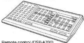
If you haven't already done so, carefully remove the DSP system and its accessories from the box and wrapping material. You should find the DSP system itself, a remote control unit, batteries for the remote control unit, a pair of stereo audio cables and a video cable. The DSP-A700 also provides remote control cables when purchased as a set with the AVS-700. See the AVS-700's operation manual.

Batteries (4 for the DSP-A700, 2 for the DSP-E300)
Remote control (DSP-A700)

Remote control (DSP-E300)

Pin cable, audio

Pin cable, video

natural_image
Technical illustration of remote cables (DSP-A700 only) with no visible text or symbols on the diagrams themselves.Installing the Remote Control Unit Batteries
Since the remote control unit will be used for many of the DSP control operations, you should begin by installing the supplied batteries.
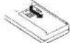
- Turn the remote control unit over and slide the battery compartment cover downward in the direction of the arrow.
- Insert the batteries (R06 or AA types for the DSP-A700; R03 or AAA types for the DSP-E300), being careful to align them with the polarity markings on the inside of the battery compartment.
- Close the battery compartment cover.
DSP-A700 remote control

natural_image
Three-step diagram showing a mechanical assembly with arrows indicating direction (no text or symbols)DSP-E300 remote control


SETUP & ADJUSTMENT
- When you notice that remote control operation has become erratic, or the distance from which the remote control will function has decreased markedly, it's time to replace the batteries. Always replace all batteries at the same time.
- With the remote control supplied with the DSP-A700, make sure that the LEARN/NORM switch is set to the NORM position for normal operation.
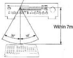
- This remote control used an advanced, highly directional infrared beam. Be sure to aim the remote control directly at the infrared receiver on the main unit when operating. The remote control will not operate properly if aimed away from the receiver or if strong light falls on the receiver.
Infrared receiver
Digital Sound Field Processing
What is it that makes live music so good? Today's advanced sound reproduction technology lets you get extremely close to the sound of a live performance, but chances are you'll still notice something missing, the acoustic environment of the live concert hall. Extensive research into the exact nature of the sonic reflections that create the ambience of a large hall has made it possible for Yamaha engineers to bring you this same sound in your own listening room, so you'll feel all the sound of a live concert. What's more, our technicians, armed with sophisticated measuring equipment, have even made it possible to capture the acoustics of a variety of actual concert halls, jazz clubs, theaters, etc. from around the world, to allow you to accurately recreate one of a large variety of actual live performance environments, all in your own home.
SETUP & ADJUSTMENT
Yamaha Active Servo Technology
The Yamaha Active Servo Technology concept began with Yamaha trying to decrease the size of speaker units while retaining excellent bass response. This is accomplished through two major features—the Helmholtz resonator and the negative impedance drive.
According to Helmholtz resonance theory, small amplitudes within the speaker cabinet can be output from the bass port as large waves if the cabinet volume and port size are scaled to a certain ratio. For this to occur, however, certain precise amplitude and phase relationships must be maintained.
By using a negative-impedance drive circuit, the Yamaha Active Servo Technology amplifier tailors the drive signal to the exact conditions required for the particular speaker design, producing an excellent bass response that resembles that of much larger systems. In addition, this speaker design reduces intermodulation distortion and transient distortion and produces a sharper acoustic image.
Dolby Pro Logic Surround
The Dolby Pro Logic Surround Decoder program lets you experience the dramatic realism and impact of Dolby Surround movie theater sound in your own home. Dolby Pro Logic gets its name from its professional-grade steering logic circuitry, which provides greater effective channel separation for a much higher degree of realism than the "passive" Dolby Surround circuits found in today's typical home audio/video equipment. Dolby Pro Logic Surround provides a true center channel, so that there are four independent channels, unlike passive Dolby Surround which has in effect only three channels: left, right, and rear. This center channel allows listeners seated in even less-than-ideal positions to hear the dialog originating from action on the screen while getting a stereo effect as well.
Manufactured under license from Dolby Laboratories Licensing Corporation. Additionally licensed under one or more of the following patents: U.S. numbers 3632886, 3746792 and 3959590; Canadian numbers 1004603 and 1037887. "Dolby" and the Double-D symbol are trademarks of Dolby Laboratories Licensing Corporation.
SETUP & ADJUSTMENT
4-Channel or 6-Channel Operation
The DSP system has been designed to provide the best sound-field quality with a full six-channel amplifier and speaker configuration, using two extra pairs of speakers to generate the sound field plus one more for dialog when using Dolby Pro Logic Surround decoding. We therefore recommend that you use a six-channel setup, and we'll base our system setup instructions on the six-channel configuration. A four-channel system using only one extra pair of speakers for the sound field plus one for the dialog will still provide impressive ambience and effects, however, and may be a good way to begin with your DSP system. You can always upgrade to the full six channels later. In the 4-channel mode, the full 6-channel processing is still performed, but with the front speakers used both for the main channels and the front effect channels.
Whether to Use a Center Dialog Speaker
To approach as nearly as possible the dynamic sound of professional Dolby systems in movie theaters, the DSP system breaks the Dolby Surround encoded stereo signal into several different channels: a center channel for dialog, the main left and right channels, and rear surround channels. A typical system setup includes seven speakers, two of which (the FRONT speakers) are for sound field processing only and are not used by the Dolby Pro Logic Surround system.
If for some reason it is not practical to use a center speaker, it is possible to eliminate it. The "phantom" mode is used in this case to route the dialog to the main speakers. Best results are obtained with the full system, however.
It is also possible to further expand your system with the addition of a subwoofer and amplifier. You may wish to choose the convenience of a Yamaha Active Servo Processing Super Woofer System which has its own built-in power amp.
SETUP & ADJUSTMENT
1-2. SETUP
Before You Start Making Connections Make Sure All Related Electronic Components Are Turned OFF.
REAR PANEL
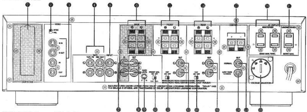
(DSP-A700 General Model)
Parts in shaded areas are not present on the DSP-E300.
CAUTION: TO PREVENT ELECTRIC SHOCK DO NOT USE THIS (POLARIZED) PLUG WITH AN EXTENSION CORD, RECEPTACLE OR OTHER OUTLET UNLESS THE BLADES CAN BE FULLY INSERTED TO PREVENT BLADE EXPOSURE.
SETUP & ADJUSTMENT
Active Servo Processing Cartridge Compartment (DSP-A700 only)
When using Active Servo processing speakers for the main channels, the cartridge supplied with the speakers must be plugged in here. The cartridge tailors the main-channel amplifier to the exact characteristics of the particular speakers used. The amplifier is automatically set up for conventional speakers when no cartridge is inserted.
② Video NTSC/PAL Switch (General Model only)
When using the video superimpose feature, this switch must be set to the position corresponding to the television broadcast standard in your area.
35 Video Superimpose Input/Output Jacks
Used to display the DSP system's current operating status on your video monitor, superimposed on the picture. Connect the OUT jack to the VIDEO IN jack of your monitor. Connect your VCR or other video signal source to the IN jack. Alternatively, the S OUT and S IN jacks can be used for higher resolution and improved picture quality if your VCR and monitor are equipped with S connectors. The S inputs take priority if both inputs are connected.
② Tape Rec Out and Playback Jacks
Connect the inputs and outputs of a stereo tape deck for convenient recording and playback via the DSP system (the effect sound cannot be recorded).
③ Input Jacks
Accept input from a preamplifier, the "PRE OUT" or "TAPE REC" outputs from an integrated amplifier, or direct input from a line-level source.
5 Main Speaker Terminals (DSP-A700 only)
When using the DSP-A700's built-in main-channel amplifier, connect the main speakers here. The jumper bars must be
plugged in to connect the MAIN IN jacks to the MAIN OUT jacks.
7 Main In Jacks (DSP-A700 only) Line input to built-in main-channel amplifier. Connected with jumper bars to MAIN OUT jacks when the built-in amplifier is used. Not connected when using an external power amplifier.
Main Out Jacks Main-channel line output. Connected with jumper bars to MAIN IN jacks when the built-in amplifier is used (DSP-A700 only). Connected to input jacks of external stereo power amplifier (MAIN IN or TAPE PLAY jacks of integrated amplifier or receiver) otherwise.
③ Main Level Control Adjusts the main-channel line output level at the MAIN OUT jacks. Used to achieve balance between the main and effect speakers.
⑩ Front Mix Switch Set to "6ch" when setting up a full 6-channel sound field system, or to "4ch" when setting up a 4-channel system.
10 Front Speaker Terminals When using the built-in front-channel amplifier, connect the front speakers here.
12 Front Active Servo Switch Set this switch to ON when using Yamaha YST-SE10 Active Servo processing speakers for the front channels. Set to OFF when using conventional speakers.
③ Front Out Jacks Front-channel line output. Not connected when the built-in amplifier is used. Can be connected to input jacks of an external stereo power amplifier driving the front effect speakers.
SETUP & ADJUSTMENT
① Rear Speaker Terminals
When using the built-in rear-channel amplifier, connect the rear speakers here.
Rear Active Servo Switch
Set this switch to ON when using Yamaha YST-SE10 Active Servo processing speakers for the rear channels. Set to OFF when using conventional speakers.
16 Rear Out Jacks
Rear-channel line output. Not connected when the built-in amplifier is used. Can be connected to input jacks of an external stereo power amplifier driving the rear effect speakers.
⑤ Center Speaker Terminals
When using the built-in center-channel amplifier, connect the center speakers here.
⑬ Center Subwoofer Out Jack
Use this jack for output to a mono amplifier driving a sub-
woofer. This output operates regardless of the setting of the
center mode switch. Frequencies above 200Hz are filtered out
so that only the bass range remains.
⑩ Center Out Jack
Center-channel line output. Not connected when the built-in amplifier is used. Can be connected to input jack of an external stereo power amplifier driving the center speaker.
② Switched AC Outlets (U. S. A., Canada, and General Model) You may plug other audio components into these sockets as long as their combined power consumption does not exceed 200 watts. "Switched" means that these components are turned on and off by the DSP system's power switch.
④ Unswitched AC Outlet (U. S. A., Canada, and General Model) The total power consumption of audio components plugged into this socket should not exceed 200 watts. "Unswitched" means that power is available even when the DSP system is off.
2 Voltage Selector (General Model only)
Be sure to set to the line voltage in your area before applying power. Consult your dealer if unsure of the correct setting.
NOTE: If an external power amplifier is connected to the front, rear, or center line output jacks, the corresponding internal amplifier will be turned off and no output will be available at the speaker terminals.
SETUP & ADJUSTMENT
Voltage Selector Switch Setting—Important (General Model)
You must be sure that the VOLTAGE SELECTOR switch on the rear panel is set to the correct line voltage before plugging the power cord into a wall socket. Ask your dealer if unsure of the correct setting.
Yamaha Active Servo Processing Cartridge (DSP-A700 only)
If Yamaha Active Servo processing speakers are to be used for the main channel, the cartridge supplied with the speakers must be inserted in the cartridge compartment.
Rear-Panel Switch and Control Settings
There are several switches and controls on the rear panel that you'll have to check before operating your system, and it's a good idea to do it before you connect cables. Locate the MAIN LEVEL (③) control and FRONT MIX (⑪) slide switch at the bottom of the MAIN terminal group. Make sure the MAIN LEVEL control is set to its center click position and that the FRONT MIX switch is set to "6ch" for six-channel operation.
In a 4-channel system, set the FRONT MIX switch to "4ch".
Next, check the settings of the ACTIVE SERVO slide switches (19) and (18) in the FRONT and REAR terminal groups. Set each switch to ON if YST-SE10 Yamaha Active Servo processing speakers will be used for the corresponding channels or to OFF if conventional speakers will be used.
Finally, if the video superimpose feature will be used to display operating status information on your video monitor, set the NTSC/PAL switch (2) to the position corresponding to the television broadcast standard in your area. (General model only)
SETUP & ADJUSTMENT
Speakers and Speaker Placement
Your six-channel system will require three speaker pairs: the MAIN SPEAKERS (your normal stereo speakers), the FRONT SPEAKERS, and the REAR SPEAKERS, plus a CENTER SPEAKER. You may also be using a subwoofer.
You will probably use your present stereo speaker system for the MAIN SPEAKER pair. The front, rear and center speakers do not need to be of such high quality. But they should have enough power handling capacity to accept the maximum output of the DSP system or the external amps that will drive them.
Place the MAIN SPEAKERS in the normal position.
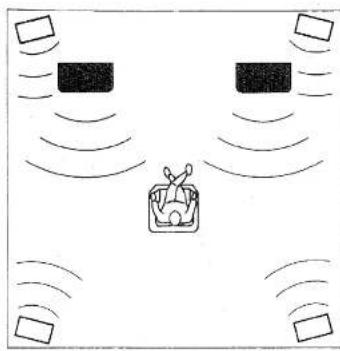
Place the FRONT SPEAKERS further apart than the MAIN SPEAKERS, on either side of and a few feet behind and above the MAIN SPEAKER pair.
Place the REAR SPEAKERS behind your listening position. They should be nearly six feet up from the floor.
Place the CENTER SPEAKER precisely between the two MAIN SPEAKERS. (To avoid interference, keep the speaker above or below the television monitor, or use a magnetically shielded speaker.)
If using a SUBWOOFER such as a Yamaha Active Servo Sub-
woofer System, the position of the speaker is not so critical because low bass tones are not highly directional.
NOTE: The Yamaha NS-C70 speaker, available in some countries, is an ideal choice for the center speaker.

natural_image
Isometric line drawing of a room with three labeled chairs and a person in the foreground (no text or symbols)
Main Speaker

Effect Speaker

Center Speaker
SETUP & ADJUSTMENT
natural_image
Simple line drawing of a robot with motion lines and control points, no text or symbols present6-Channel Configuration

Main Speaker (For source sound reproduction)

Effect Speaker (For effect sound reproduction) (Place the speakers in a high place.)

natural_image
Diagram of a vehicle with two cars and a box, showing sound waves around it (no text or symbols)4-Channel Configuration

Main Speaker. (For source sound + effect sound reproduction)

Effect: Speaker (For effect sound reproduction) (Place the speakers in a high place.)
General Instructions for Connections
Use the supplied stereo cables or an equivalent high-quality connection cable.
Make sure that you have the left (L) and right (R) channels correctly connected. That means that jacks marked "L" on the DSP system must be connected to jacks marked "L" on other units. Likewise with the "R" jacks. This is easy if you remember to always use the red plugs for the "R" jacks and the other plugs for the "L" jacks.
With speaker connections you must also be sure that the polarity is correct. For each amplifier and each channel, connect the plus (+) terminal of the amplifier to the plus terminal of the speaker, and connect the minus (−) terminal of the amplifier to the minus terminal of the speaker. To keep track of polarity, use a speaker cable that has one of the two wires marked by a stripe or a different color.
SETUP & ADJUSTMENT
CONNECTING AN A/V SELECTOR TO YOUR DSP SYSTEM
The Yamaha AVS-700 A/V Selector provides an ideal way to choose between a variety of sources for input to your DSP system. Refer to the AVS-700 manual and connect all of your source equipment to that unit. Then, connect the FIXED OUTPUT jacks of the AVS-700 to the INPUT jacks of the DSP system with a stereo pin cable. Make sure that the "L" output from the AVS-700 is connected to the "L" input on the DSP system, and that the "R" output from the AVS-700 is connected to the "R" input on the DSP system.
DSP-A700 Only: Connect the MAIN speakers to the MAIN speaker output terminals of the DSP-A700. Make sure that the jumper bars between the MAIN OUT and MAIN IN jacks on the DSP-A700 are in place. It is also possible to use an external power amplifier if more power is desired. In this case, remove the jumper bars and connect as for the DSP-E300 below.
NOTE: In order to have the POWER key on the remote control unit control the DSP-A700 as well as the AVS-700, the DSP-A700's power cord should be plugged into the AVS-700's SWITCHED outlet.
DSP-E300 Only: Connect the MAIN OUT jacks on the DSP-E300 to the INPUT jacks of a stereo power amplifier with a second stereo pin cable—making sure to connect the left and right chan-
nels correctly. Connect the MAIN speakers to the speaker output terminals of the power amplifier.

flowchart
graph TD
    A["Main Speaker"] --> B["Power Amplifier"]
    C["Main Speaker"] --> B
    B --> D["DSP System"]
    D --> E["Fixed Output"]
    E --> F["AVS-700 A/V Selector"]
    B -->|Input| D
    B -->|Input| E
    style A fill:#f9f,stroke:#333
    style C fill:#f9f,stroke:#333
    style B fill:#ccf,stroke:#333
    style D fill:#cfc,stroke:#333
    style E fill:#fcc,stroke:#333
SETUP & ADJUSTMENT
CONNECTING AN INTEGRATED STEREO AMPLIFIER OR STEREO RECEIVER TO YOUR DSP-E300
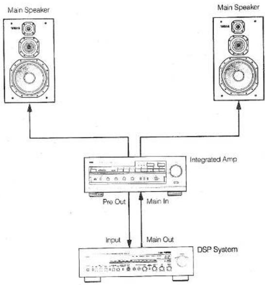
Using an Integrated Amplifier or Stereo Receiver with PRE OUT and MAIN IN Terminals
Some integrated amplifiers and stereo receivers have PRE OUT and MAIN IN jacks which permit the preamplifier and power amplifier sections to function independently. If your integrated amplifier or stereo receiver has these jacks, begin by removing the jumpers that connect the PRE OUT and MAIN IN jacks (or decouple the preamplifier and power amplifier using the appropriate switch—refer to your amplifier or receiver operation manual).
Connect the amplifier's PRE OUT jacks to the DSP-E300's INPUT jacks with a stereo pin cable. Make sure that the "L" output from the amplifier is connected to the "L" input on the DSP system, and that the "R" output from the amplifier is connected to the "R" input on the DSP system.
Connect the MAIN OUT jacks on the DSP-E300 to the MAIN IN jacks on your integrated amplifier or receiver with a second stereo pin cable—making sure to connect the left and right channels correctly. Connect the MAIN speakers to the speaker output terminals of your integrated amplifier or receiver.
flowchart
graph TD
    A["Main Speaker"] --> B["Integrated Amp"]
    C["Main Speaker"] --> B
    B --> D["DSP System"]
    D --> E["Input"]
    D --> F["Pre Out"]
    D --> G["Main In"]
    D --> H["Main Out"]
SETUP & ADJUSTMENT
Using an Integrated Amplifier or Stereo Receiver that Does Not Have PRE OUT and MAIN IN Terminals
If your integrated amplifier is NOT equipped with PRE OUT and MAIN IN jacks, the DSP-E300 must be connected to the amplifier or receiver tape record and playback jacks. The DSP-E300 provides additional TAPE PB and REC OUT jacks so you will still have a place to connect your tape deck.
Connect the amplifier or receiver TAPE REC (or TAPE OUT) jacks to the DSP-E300's INPUT jacks with a stereo pin cable. Make sure that the "L" output from the amplifier or receiver is connected to the "L" input on the DSP system, and that the "R" output from the amplifier or receiver is connected to the "R" input on the DSP system.
Connect the MAIN OUT jacks on the DSP-E300 to the TAPE PLAY (or TAPE IN) jacks on your amplifier or receiver with a second stereo pin cable—making sure to connect the left and right channels correctly. Connect the MAIN speakers to the speaker output terminals of the amplifier or receiver.
NOTE: If your system includes a tape deck which has been displaced by connecting the DSP-E300 to the TAPE jacks, reconnect your tape deck to the DSP-E300's TAPE PB and TAPE REC OUT jacks. TAPE REC OUT from the DSP system goes to the INPUT jacks on your tape deck, and the DSP-E300's TAPE PB jacks should be connected to the tape deck's OUTPUT jacks. See
"Selecting a Tape Deck Connected to the DSP System's TAPE Terminals" on page 28.

flowchart
graph TD
    A["Main Speaker"] --> B["Tape Rec"]
    C["Main Speaker"] --> D["Tape Play or Tape In"]
    B --> E["DSP System"]
    D --> E
    E --> F["Tape PB"]
    E --> G["Rec Out"]
    E --> H["Output"]
    E --> I["Tape Deck"]
    J["Integrated Amp"] --> E
    K["Input"] --> E
SETUP & ADJUSTMENT
CONNECTING A COMPONENT PREAMPLIFIER TO YOUR DSP SYSTEM
Connect the PRE OUT jacks of the preamplifier (control amplifier) to the DSP system's INPUT jacks with a stereo pin cable. Make sure that the "L" output from the preamplifier is connected to the "L" input on the DSP system, and that the "R" output from the preamplifier is connected to the "R" input on the DSP system.
DSP-A700 Only: Connect the MAIN speakers to the MAIN speaker output terminals of the DSP-A700. Make sure that the jumper bars between the MAIN OUT and MAIN IN jacks on the DSP-A700 are in place. It is also possible to use an external power amplifier if more power is desired. In this case, remove the jumper bars and connect as for the DSP-E300 below.
DSP-E300 Only: Connect the MAIN OUT jacks on the DSP-E300 to the INPUT jacks of a stereo power amplifier with a second stereo pin cable—making sure to connect the left and right channels correctly. Connect the MAIN speakers to the speaker output terminals of the power amplifier.

flowchart
graph TD
    A["Main Speaker"] --> B["Control Amplifier"]
    A --> C["Power Amplifier"]
    B --> D["Pre Out"]
    C --> E["DSP System"]
    D --> F["Input"]
    E --> G["Main Output"]
    F --> H["Main Speaker"]
    G --> I["Main Speaker"]
    H --> J["Main Speaker"]
    I --> K["Main Speaker"]
SETUP & ADJUSTMENT
CONNECTING THE EFFECT SPEAKERS TO THE DSP SYSTEM
Connect the FRONT speakers to the FRONT speaker output terminals of the DSP system.
No FRONT speakers are used with a 4-channel system.
Connect the REAR speakers to the REAR speaker output terminals of the DSP system.
Connect the CENTER speaker to the CENTER speaker output terminals of the DSP system. If you will not be using a CENTER speaker, be sure to set the front-panel CENTER MODE switch to PHANTOM.
NOTE: The speaker connections above are fine for most applications. If for some reason, however, you wish to use an external power amp for any or all of the effect channels, connect the line level output jack(s) for each channel (NORMAL jack if CENTER channel) to the INPUT jacks of the external amp and connect the corresponding speaker pair to the speaker terminals of the external amp.

flowchart
graph TD
    L1["Front Effect Speaker"] --> DSP_System["DSP System"]
    R1["Front Effect Speaker"] --> DSP System
    R2["Front Effect Speaker"] --> DSP System
    DSP System --> L2["Rear Effect Speaker"]
    DSP System --> R3["Rear Effect Speaker"]
    DSP System --> R4["Rear Effect Speaker"]
    DSP System --> R5["Rear Effect Speaker"]
    DSP System --> R6["Rear Effect Speaker"]
    DSP System --> R7["Rear Effect Speaker"]
    DSP System --> R8["Rear Effect Speaker"]
    DSP System --> R9["Rear Effect Speaker"]
    DSP System --> R10["Rear Effect Speaker"]
    DSP System --> R11["Rear Effect Speaker"]
    DSP System --> R12["Rear Effect Speaker"]
    DSP System --> R13["Rear Effect Speaker"]
    DSP System --> R14["Rear Effect Speaker"]
    DSP System --> R15["Rear Effect Speaker"]
    DSP System --> R16["Rear Effect Speaker"]
    DSP System --> R17["Rear Effect Speaker"]
    DSP System --> R18["Rear Effect Speaker"]
    DSP System --> R19["Rear Effect Speaker"]
    DSP System --> R20["Rear Effect Speaker"]
    DSP System --> R21["Rear Effect Speaker"]
    DSP System --> R22["Rear Effect Speaker"]
    DSP System --> R23["Rear Effect Speaker"]
    DSP System --> R24["Rear Effect Speaker"]
    DSP System --> R25["Rear Effect Speaker"]
    DSP System --> R26["Rear Effect Speaker"]
    DSP System --> R27["Rear Effect Speaker"]
    DSP System --> R28["Rear Effect Speaker"]
    DSP System --> R29["Rear Effect Speaker"]
    DSP System --> R30["Rear Effect Speaker"]
    DSP System --> R31["Rear Effect Speaker"]
    DSP System --> R32["Rear Effect Speaker"]
    DSP System --> R33["Rear Effect Speaker"]
    DSP System --> R34["Rear Effect Speaker"]
    DSP System --> R35["Rear Effect Speaker"]
    DSP System --> R36["Rear Effect Speaker"]
    DSP System --> R37["Rear Effect Speaker"]
    DSP System --> R38["Rear Effect Speaker"]
    DSP System --> R39["Rear Effect Speaker"]
    DSP System --> R40["Rear Effect Speaker"]
    DSP System --> R41["Rear Effect Speaker"]
    DSP System --> R42["Rear Effect Speaker"]
    DSP System --> R43["Rear Effect Speaker"]
    DSP System --> R44["Rear Effect Speaker"]
    DSP System --> R45["Rear Effect Speaker"]
    DSP System --> R46["Rear Effect Speaker"]
    DSP System --> R47["Rear Effect Speaker"]
    DSP System --> R48["Rear Effect Speaker"]
    DSP System --> R49["Rear Effect Speaker"]
    DSP System --> R50["Rear Effect Speaker"]
    DSP System --> R51["Rear Effect Speaker"]
    DSP System --> R52["Rear Effect Speaker"]
    DSP System --> R53["Rear Effect Speaker"]
    DSP System --> R54["Rear Effect Speaker"]
    DSP System --> R55["Rear Effect Speaker"]
    DSP System --> R56["Rear Effect Speaker"]
    DSP System --> R57["Rear Effect Speaker"]
    DSP System --> R58["Rear Effect Speaker"]
    DSP System --> R59["Rear Effect Speaker"]
    DSP System --> R60["Rear Effect Speaker"]
    DSP System --> R61["Rear Effect Speaker"]
    DSP System --> R62["Rear Effect Speaker"]
    DSP System --> R63["Rear Effect Speaker"]
    DSP System --> R64["Rear Effect Speaker"]
    DSP System --> R65["Rear Effect Speaker"]
    DSP System --> R66["Rear Effect Speaker"]
    DSP System --> R67["Rear Effect Speaker"]
    DSP System --> R68["Rear Effect Speaker"]
    DSP System --> R69["Rear Effect Speaker"]
    DSP System --> R70["Rear Effect Speaker"]
    DSP System --> R71["Rear Effect Speaker"]
    DSP System --> R72["Rear Effect Speaker"]
    DSP System --> R73["Rear Effect Speaker"]
    DSP System --> R74["Rear Effect Speaker"]
    DSP System --> R75["Rear Effect Speaker"]
    DSP System --> R76["Rear Effect Speaker"]
    DSP System --> R77["Rear Effect Speaker"]
    DSP System --> R78["Rear Effect Speaker"]
    DSP System --> R79["Rear Effect Speaker"]
    DSP System --> R80["Rear Effect Speaker"]
    DSP System --> R81["Rear Effect Speaker"]
    DSP System --> R82["Rear Effect Speaker"]
    DSP System --> R83["Rear Effect Speaker"]
    DSP System --> R84["Rear Effect Speaker"]
    DSP System --> R85["Rear Effect Speaker"]
    DSP System --> R86["Rear Effect Speaker"]
    DSP System --> R87["Rear Effect Speaker"]
    DSP System --> R88["Rear Effect Speaker"]
    DSP System --> R89["Rear Effect Speaker"]
    DSP System --> R90["Rear Effect Speaker"]
    DSP System --> R91["Rear Effect Speaker"]
    DSP System --> R92["Rear Effect Speaker"]
    DSP System --> R93["Rear Effect Speaker"]
    DSP System --> R94["Rear Effect Speaker"]
    DSP System --> R95["Rear Effect Speaker"]
    DSP System --> R96["Rear Effect Speaker"]
    DSP System --> R97["Rear Effect Speaker"]
    DSP System --> R98["Rear Effect Speaker"]
    DSP System --> R99["Rear Effect Speaker"]
SETUP & ADJUSTMENT
1-3. OPTIONAL CONNECTIONS
This section deals with:
- Adding a subwoofer to your system.
• Using the video superimpose capability.
If you do not plan to use any of these capabilities skip ahead to the "CONTROLS & ADJUSTMENTS" section which follows.
ADDING A SUBWOOFER
In particularly large listening rooms you may wish to add a subwoofer to reinforce the bass frequencies. The DSP system provides a line-level subwoofer output which contains only the frequencies under 200 Hz from the main channels. Connect the CENTER OUT LOW PASS jack to the INPUT jack of the subwoofer amplifier, and connect the speaker terminals of the subwoofer amplifier to the subwoofer. With some subwoofers, including the Yamaha Active Servo Processing Subwoofer System, the amplifier and subwoofer are in the same unit.
NOTE: The Yamaha Active Servo Processing Subwoofer System has an additional input connection which can be used to take input directly from the main speakers, but this should not be used if Yamaha Active Servo processing speakers are used for the main speakers. Use the CENTER OUT LOW PASS jack on the rear panel instead.
SETUP & ADJUSTMENT
VIDEO SUPERIMPOSE
If your DSP system will be used in conjunction with a video system, this connection allows the DSP system to display program titles and parameter data on your video monitor screen, superimposed over the video image. Refer to "2-6. SUPERIMPOSED VIDEO PROGRAM/PARAMETER DISPLAY" on page 33 for operation details.
If your video cassette recorder or video disc player and your monitor are equipped with "S" (high-resolution) video terminals, connect the "S" video output from your video cassette recorder or video disc player to the DSP system's VIDEO S IN jack, and connect the DSP system's VIDEO S OUT jack to the "S" video input of your monitor. Otherwise, connect the composite video output from your video cassette recorder or video disc player to the VIDEO IN jack of the DSP system, and connect the DSP system's VIDEO OUT jack to the composite video input of your monitor.
NOTE: The video signal from your video cassette deck or video disc player will not be sent to the video monitor via the DSP system's terminals when the DSP system power is OFF.
NOTE: If your DSP system is the General Model, be sure the VIDEO NTSC/PAL switch has been correctly set to the television broadcast standard in your area. U.S. and Canadian models have no switch and use the NTSC standard, while other models without a switch use the PAL standard.
NOTE: If video signals are sent to both VIDEO S IN and VIDEO IN jacks, the signals will be sent to their respective output jacks, but only the VIDEO S OUT signal will have the DSP system's parameter data superimposed on it.

flowchart
graph TD
    A["Video Out"] --> B["Central Device"]
    C["Video In"] --> B
    D["Video Deck, etc"] --> B
    E["TV Monitor"] --> B
    B --> F["Video Out"]
    style B fill:#f9f,stroke:#333,stroke-width:2px
SETUP & ADJUSTMENT
1-4. CONTROLS & ADJUSTMENTS
FRONT PANEL

(DSP-A700 General Model)
Parts in shaded areas are not present on the DSP-E300.
① Power Switch
Program Select Switches/Indicators
Selects the digital processing program to be used. The indicator lights to show your choice.
③ Parameter Display
Normally shows whether program Type A or Type B has been selected. When a program parameter is being viewed or altered, shows the name of that parameter.
4 Effect Switch
Normally ON, this switch can be turned OFF to disable output from all effect speakers.
5 Program Number Display
Shows the number of the currently selected program. When a program parameter is being viewed or altered, displays its value.
6 Phones Jack
Plug in headphones here for private listening. If the FRONT MIX and EFFECT switches are on, the effect channels will be heard along with the main channels. Otherwise the main channels only will be heard.
⑦ DSP Test Switch
When on, sends a signal to the main, front effect and rear effect speakers in turn, for easy comparison of level settings.
SETUP & ADJUSTMENT
DSP Effect Level Controls
Used for setting the volume levels of the sound field effect speakers for best balance with the main speakers.
⑲ Dolby Pro Logic Test Switch
When on, sends a signal to the main left, center, main right, and rear speakers in turn, for easy comparison of level settings.
⑩ Dolby Pro Logic Effect Level Controls
Used for setting the volume levels of the center and surround speakers for best balance with the main speakers.
Center Mode Switch
Set to the ON position if you will be using a center speaker. Set to the PHANTOM position if you wish the center channel information to be reproduced through the left and right channel main speakers. The OFF position is used only when adjusting the input balance control.
Input Balance Control
This adjusts input signal balance to optimize the operation of the Dolby Pro Logic Surround matrix circuitry. Set the center mode switch to OFF while performing this calibration.
③ Microphone Jacks (Left and Right)
Plug one or two microphones or electronic instruments (600 ohms impedance or less) to sing or play along with the music. Certain microphones may cause howling or produce insufficient volume.
- Microphone Level Control
Adjusts the level of the source(s) plugged into the microphone jacks.
15 Tape Monitor Switch
Used when you have connected a tape deck to the DSP system's TAPE terminals to select that tape as the source. (See pages 15 and 28.)
Bass, Midrange, and Treble Controls (DSP-A700 only) Adjust the sound to match your tastes. Can also be used to compensate for room acoustics. Defeated in the center position.
Master Volume Control
Simultaneously controls signal level at all outputs: front, main, rear, center, and subwoofer. (This does not affect TAPE REC OUT level.)
SETUP & ADJUSTMENT
REMOTE CONTROL UNIT (for DSP-A700)
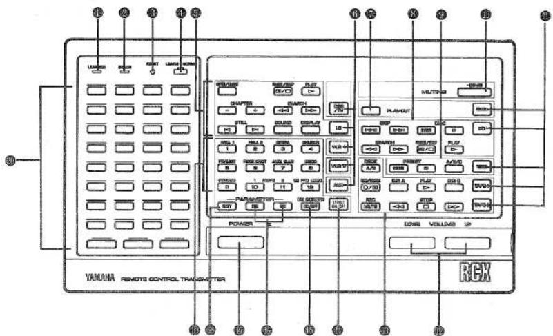
① Learned Function Indicator
In Learn mode, blinks to indicate that the key just pressed is ready for learning input. In Normal mode, lights when a learned key is pressed to show that a control signal has been sent to your equipment.
② Error Indicator
In Learn mode, lights to indicate that the key just pressed has already learned a function. In Normal mode, lights when a key is pressed that has no learned function.
Reset Button
Used in Learn mode to erase a learned function.
Learn/Normal Mode Switch
Set to Normal mode for normal remote control operation. Set to Learn mode for learning new control functions (see page 34).
⑤ LD Function Keys
Operate functions on your Yamaha RS-compatible LD player.
SETUP & ADJUSTMENT
6 Source Select Keys (Group 1)
Select the BS/TV (tuner), LD, VCR1, VCR2, or AUX source on the AVS-700 A/V selector. For Yamaha components with the RS mark.
7 Turntable Play/Cut Key
Operate the Play/Cut function of your Yamaha RS-compatible turntable.
CD Function Keys
Operate functions on your Yamaha RS-compatible CD player.
⑨ Tuner Function Keys
Operate Yamaha RS-compatible tuner functions.
Muting Key
Operates the Muting function of the AVS-700 A/V Selector.
⑪ Source Select Keys (Group 2)
Select the PHONO (turntable), CD, TUNER, TAPE1, or TAPE2 source on the AVS-700 A/V selector. For Yamaha components with the RS mark.
12 Master Volume Up and Down Keys
Increase (UP) or decrease (DOWN) the master volume level.
Tape Deck Function Keys
Operate Yamaha RS-compatible tape deck functions.
DSP Effect Mute Key
Mutes the effect speakers for comparisons and sound checks.
15 On Screen Display Key
Selects whether or not to display the program name and parameters on the connected monitor screen.
- Parameter Increment and Decrement Keys Edit program parameters.
Power On/Off Key Turns AVS-700 A/V Selector on and off. (Also controls DSP-A700 if plugged into AVS-700 SWITCHED outlet.)
⑬ Next Parameter Key Selects program parameters.
Program Select Keys (1 through 12) Select programs 1 through 12.
Learnable Function Keys Can be used to control a variety of audio and video equipment in your system or other appliances equipped with infrared remote control receivers. See page 34 for details.
SETUP & ADJUSTMENT
REMOTE CONTROL UNIT (for DSP-E300)

On Screen Display Key
Selects whether or not to display the program name and parameters on the connected monitor screen.
② Program Select Keys (1 through 12) Select programs 1 through 12.
③ Next Parameter Key Selects program parameters.
Effect ON/OFF Key
Mutes the effect speakers for comparisons and sound checks.
⑤ Parameter Increment and Decrement Keys Edit program parameters.
⑥ Master Volume Up and Down Keys
Increase (UP) or decrease (DOWN) the master volume level.
SETUP & ADJUSTMENT
1-5. ADJUSTMENT
PREPARATION
- Set all volume controls—on the main amp (preamp) and effect power amplifiers—to their MINIMUM positions.
- Turn on the power to all system components. The DSP system is turned on by pressing the POWER switch on the front panel.
Front Panel

- Use the MASTER VOLUME control on the front panel or the MASTER VOLUME keys on the remote control to set the master volume to its lowest level. If you are using external power amplifiers on any channels, any volume controls on the power amps should be set to maximum.

- Select your video cassette deck or video disc player (or other Dolby Surround encoded program source) on your A/V selector, integrated amplifier, preamplifier, or receiver.
-
Begin playback of Dolby Surround encoded program material.
-
Increase the setting of the volume control on your preamplifier, integrated amplifier, or receiver to about the half-way point.
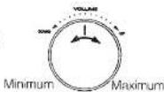
*If you are using an AVS-700 A/V selector you will be using its FIXED OUT jacks. The AVS-700 volume control will be inoperative and adjustment is unnecessary.
*Depending on the particular model of preamplifier, integrated amplifier, or receiver you are using, a slightly different volume setting may be necessary. If there is distortion on loud passages, try reducing the volume control setting slightly.
7. Use the MASTER VOLUME control on the front panel or the MASTER VOLUME keys on the remote control unit to set the master volume to a comfortable listening level.

For optimum performance—minimum noise and maximum dynamic range—it is desirable to set the volume control of your preamplifier, integrated amplifier or receiver to its center position, making any necessary adjustments to the listening level by changing the MASTER VOLUME control setting on the DSP system.
SETUP & ADJUSTMENT
INPUT BALANCE ADJUSTMENT
This adjustment should be performed to assure optimum performance of the Dolby Pro Logic Surround Decoder.
- Press the PRO LOGIC switch (program #12).

- Set the front panel CENTER MODE switch to the OFF position.

-
Begin playback of Dolby Surround encoded program material.
-
While listening to spoken dialog, adjust the input balance control so that the dialog volume (heard from the left and right main and rear speakers) is reduced to minimum. (During normal operation, this dialog is reproduced over the center channel.)
-
When you have completed this adjustment, be sure to return the front panel CENTER MODE switch to the NORM or PHANTOM setting, depending on whether you are using a center speaker (see pages 6 and 21).
MAIN/EFFECT SPEAKER LEVEL BALANCE ADJUSTMENT
This operation uses an internal pink-noise generator to balance the levels of the main and effect speakers. It is most convenient to perform this operation using two people, one to adjust the controls of the DSP system and another to sit at the normal listening position and check the balance.
- Depress the DSP TEST switch on the front panel to enter test mode. A hiss-like calibration signal should be heard from the main speakers, front effect speakers, and rear speakers in turn. This sequence repeats 3 times, and is followed by another sequence of front left, center, front right, rear right, and rear left (see diagram). Adjust the MASTER VOLUME to a normal listening level.

flowchart
graph LR
    A["Main"] --> B["Front"]
    B --> C["Rear"]
    C --> D["Repeat: 3 times"]
    D --> E["Rear Left"]
    E --> F["Rear Right"]
    F --> G["Front Right"]
    G --> H["Center"]
    H --> I["Front Left"]
SETUP & ADJUSTMENT
- Adjust the DSP FRONT (for a 6-channel system) and DSP REAR level controls so that the sound coming from the corresponding speakers seems to be at the same level as that from the main speakers when you are at a normal listening position. If there is insufficient volume from the main speakers, the setting of the MAIN LEVEL control on the rear panel may be increased, but too high a setting could result in increased residual noise when listening at low volume. Volume controls on external power amplifiers may also be adjusted if necessary to achieve proper balance.
NOTE: The DSP CENTER level control is used to emphasize the dialog channel on movies, or to adjust the level of the 150 Hz to 7 kHz monophonic center channel on programs 1 through 11 to your taste.
- Depress the DOLBY PRO LOGIC TEST switch on the front panel to enter Dolby Pro Logic test mode. A calibration signal should be heard from the left main speaker, center speaker, right main speaker and rear speakers in turn (see diagram).

flowchart
graph LR
    A["Left Main"] --> B["Center"]
    B --> C["Right Main"]
    C --> D["Rear"]
    D --> A
-
Adjust the DOLBY PRO LOGIC CENTER level control so that the center speaker volume is the same as that of either of the main speakers.
-
Adjust the DOLBY PRO LOGIC REAR level control so that the combined rear speaker volume is the same as that of each of the other speakers.
NOTE: If not using a center speaker, be sure to set the front panel CENTER MODE switch to the PHANTOM position. You will then hear the center channel test tone from the left and right main speakers.
After completing this adjustment, turn off the front panel TEST button.
NOTE: Once you have completed these adjustments, use only the DSP system's MASTER VOLUME control to adjust listening volume. Do not change any other volume settings in the system.
GENERAL OPERATION
2-1. INPUT SOURCE SELECTION
Selecting a Source Connected to Your A/V Selector, Integrated Amplifier, Receiver, or Preamplifier
If the source you wish to hear is connected to your A/V Selector, Integrated Amplifier, Receiver, or Preamplifier, just select the source in the usual way using that unit's controls.

NOTE: When selecting one of the sources described above, make sure that the DSP system's TAPE MONITOR switch is OFF.
Selecting a Tape Deck Connected to the DSP System's TAPE Terminals
To select a tape deck connected to the DSP system's TAPE terminals, depress the front-panel TAPE MONITOR switch to turn it ON.

2-2. DIGITAL SOUND FIELD PROGRAMS
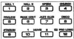
The DSP system has 12 programs for digital sound field processing, 11 from actual acoustic environments from around the world, and one program for Dolby Pro Logic surround decoding. Many of the programs contain various parameters that can be adjusted to provide an even wider range of sounds.
2-3. SELECTING SOUND FIELD PROGRAMS
- Select the desired sound field program by pressing the appropriate PROGRAM switch on the front panel or by using the PROGRAM keys on the remote control.
GENERAL OPERATION
2-4. MUTING THE EFFECT SOUND
- All sound field programs except CHURCH, PAVILION, and DOLBY PRO LOGIC have two "subprograms" (see "3-5. DESCRIPTIONS OF THE SOUND FIELD PROGRAMS" below). The sub-programs are selected using the PARAMETER DEC and INC keys on the remote control unit. The CONCERT HALL 1 program, for example, contains the sub-programs "Hall A in Europe" and "Hall B in Europe". When the CONCERT HALL 1 program is first selected, the "Hall A in Europe" sub-program will be selected and "TYPE A" will be displayed on the front panel. To select "Hall B in Europe", press the PARAMETER INC key. To return to Hall A in Europe, press the PARAMETER DEC key. The same selection procedure applies to all other programs which have sub-programs.
The EFFECT switch on the front panel and the EFFECT key on the remote control unit make it simple to compare the normal stereo sound with the fully processed effect sound.
To mute the effect sound and monitor only the main sound, press the EFFECT key or the EFFECT switch. The red EFFECT OFF indicator on the front panel will light to remind you that the effect sound is muted. Press the EFFECT key or EFFECT switch a second time to restore normal operation.

GENERAL OPERATION
2-5. DESCRIPTIONS OF THE SOUND FIELD PROGRAMS
| The following list gives brief descriptions of the sound fields produced by each of the DSP programs. Keep in mind that most of the these are precise digital recreations of actual acoustic environments, and the data for them was recorded at the locations described using sophisticated Yamaha digital sound field data acquisition equipment. | 2. CONCERT HALL 2TYPE ALive Concert: A round concert hall with a rich "surround" effect and pronounced echo.TYPE BHall C in Europe: A classic 1700-seat concert hall with pillars and ornate carvings that, by creating an extremely complex field of reflections arriving from all directions, produces a very full, rich sound.Preset ParameterINIT DLY 30msROOM SIZE 1.0 | |
| 1. CONCERT HALL 1TYPE AHall A in Europe: This is a fairly common type of concert hall in Europe. It has approximately 2500 seats and features a very beautiful (and acoustically active) wood-panel interior. The overall sound is rich but reserved.TYPE BHall B in Europe: Another wood-interior concert hall that seats a little less than 2400. Polished reflective paneling above the stage produces strong frontal reflections which tend to reinforce the direct sound from the stage. this hall has a very solid, powerful sound.Preset ParameterINIT DLY 30msROOM SIZE 1.0 | 3. OPERA HOUSETYPE ABalcony: The Opera House Balcony sound field program seats you in the balcony of a 2000-seat opera house.TYPE BMezzanine: This is the same opera house as above, but your listening position is in the front row of the mezzanine.Preset ParameterINIT DLY 20msROOM SIZE 1.0 | |
GENERAL OPERATION
| 4. CHURCHThis program recreates the acoustic environment of a modern church with a high pointed dome and columns along the sides. This interior produces a very few primary reflections.Preset ParameterINIT DLY 40msREV TIME 2.5s | 6. ROCK CONCERTTYPE AArena:A big, powerful sound suited to rock music.TYPE BThe Roxy Theatre:The ideal program for lively, dynamic rock music.The data for this program was recorded at LA's "hottest" rock live spot.Preset ParameterINIT DLY 15msROOM SIZE 1.0 |
| 5. PAVILIONThe sound field of a large, all-concrete enclosed multi-purpose pavilion which is used for exhibitions, sports, etc.Preset ParameterINIT DLY 5msREV TIME 1.9s | 7. JAZZ CLUB 1TYPE AVillage Gate:A jazz club in New York. It is in a basement and has a relatively spacious floor area. The reflection pattern is similar to that of a small hall.TYPE BCellar Club:This is a small, cozy jazz club with a low ceiling.The sound is very close and intimate.Preset ParameterINIT DLY 20msROOM SIZE 1.0 |
GENERAL OPERATION
8. DISCO
TYPE A
New York:
Discos tend to have a high-energy, "immediate" sound. This one is no exception. The room itself is circular, approximately 20 meters (65 feet) in diameter.
TYPE B
Tokyo:
A lively disco in the heart of a very lively city. The sound is dense and highly concentrated.
Preset Parameter
INIT DLY 10ms
ROOM SIZE 1.0
10. MOVIE (THEATER) 1
Independently processes the audio signal's center components (L+R) and surround components (L-R) to provide clear positioning of the dialog and a dynamic surround effect ideal for movies.
TYPE A
Adventure:
A sound field ideally suited to viewing action-packed adventure movies.
TYPE B
Standard:
This is the sound field most commonly encountered in standard movie theaters.
Preset Parameter
INIT DLY 11ms
ROOM SIZE 1.0
9. STADIUM
TYPE A
Anaheim Stadium:
This program gives you the long delays and extraordinarily spacious feel of a stadium that is no less than 300 meters (990 feet) in diameter.
TYPE B
Bowl:
An outdoor stadium with the typical bowl-shaped seating arrangement.
Preset parameter
INIT DLY 55ms
ROOM SIZE 1.0
11. MOVIE (THEATER) 2
Independently processes the audio signal's center components (L+R) and surround components (L-R) to provide clear positioning of the dialog and a dynamic surround effect ideal for movies.
TYPE A
Live:
Provides a sound field similar to a musical theater or opera house. A rich surround effect ideal for live concert or musical videotapes.
TYPE B
Concert:
Projects reverberations over a wide area. Ideal for films of concert scenes.
Preset Parameter
INIT DELAY 20ms
ROOM SIZE 1.0
GENERAL OPERATION
12. DOLBY PRO LOGIC SURROUND
Produces a stunning, surrounded-by-sound environment. Reproduces video discs, video tapes and similar sources which are Dolby Surround encoded and bear the "DOLBY SURROUND" logo.
Preset Parameter DELAY 20.0ms
NOTE: The Dolby Pro Logic Surround system is designed to be used with program material (mainly videotaped movie soundtracks) that is encoded with the Dolby Surround system. The results with material not encoded with Dolby Surround may be unnatural.
NOTE: Some amplifiers and receivers have built-in surround sound or ambience circuitry. If this is the case in your system, then be sure that the surround or ambience circuitry is off on the source amp or receiver while you are using the DSP system's Dolby Pro Logic Surround decoding function.
NOTE: If the main-channel sound is considerably altered by overadjustment of the BASS or TREBLE controls, the relationship with the center and rear channels may produce an unnatural effect.
2-6. SUPERIMPOSED VIDEO PROGRAM/PARAMETER DISPLAY
If you have connected your video cassette player or video disc player and video monitor to the DSP system as described in the "OPTIONAL CONNECTIONS" section on page 17, you can take advantage of the DSP system's capability to provide a more comprehensive display of program and parameter data.
- With the video monitor properly connected to the DSP system VIDEO OUT or VIDEO S OUT terminal and turned on, press the ON SCREEN DISPLAY key on the remote control unit.
The current program name and its parameters will be displayed on the monitor screen. The arrow-shaped cursor points to the currently selected parameter. Parameters are selected and edited using the PARAMETER UP/DOWN and INC/DEC keys as described in section 3.
- If your video cassette player or video disc player is connected, the displayed information will be superimposed on the picture from that source. If there is no video source connected or it is turned off, the information will be displayed over a solid color background (but no video signal is output from the S jacks). In this case, the color of the background will be treated as one of the program parameters and it may be changed in the same way as the other parameters.
GENERAL OPERATION
2-7. REMOTE CONTROL "LEARNING" FUNCTION (DSP-A700 only)
The DSP-700's remote control unit, in addition to controlling the most commonly used functions of your DSP-A700 and other connected Yamaha audio and video equipment, has a sophisticated "learning" function that allows it to control other equipment in your system or other household appliances equipped with infrared remote control receivers. 35 learnable function keys are provided on the remote control unit, each capable of "learning" a different remote control function.
Learning a New Remote Control Function
-
Set the LEARN/NORM switch to Learn mode.
-
Press the learnable function key that is to have a new function assigned to it. The LEARNED indicator will blink. The ERROR indicator will also be lit if this key already has a function assigned to it, but a new function may be assigned in its place if desired.
-
Aim the infrared transmitter window of the remote control unit for the equipment that is to be controlled directly into the window of the DSP-A700's remote control unit. Press and hold down the button on the other remote control unit corresponding to the new function to be learned. The ERROR indicator will light momentarily. Hold the button down until both the LEARNED and ERROR indicators are extinguished. The function has now been learned. If this step is not performed within about 10 seconds, the LEARNED indicator will go out and you will have to go back to step 2.

-
Repeat steps 2 and 3 to learn additional functions.
-
Return the LEARN/NORM switch to Normal mode to allow normal operation. Pressing the learned key will now perform the assigned function. Stick-on labels are suggested to record the functions learned by the various keys.
GENERAL OPERATION
Erasing a Learned Function
The function learned by any key can be easily altered just by repeating the learning process with a different function. It is also possible to erase a key so that it performs no function at all.
- Set the LEARN/NORM switch to the Learn mode.
- Use the point of a pencil other other similar object to press the RESET button. Both the LEARNED and ERROR indicators will blink.
- Press the key whose function is to be erased.
- Return the LEARN/NORM switch to Normal mode.
NOTE: The RCX cannot be used with some remote controllers.
NOTE: All of the memorized functions will be retained while you replace the batteries. However, if no batteries are installed for a few hours, the memory will be erased and will have to be programmed again.
NOTE: If the internal memory becomes full, it will be impossible to store functions into any key.
CREATING YOUR OWN SOUND FIELDS
3-1. SELECTING AND EDITING PROGRAM PARAMETERS
WHAT IS A SOUND FIELD?
In order to explain the impressive functions of the DSP system, let's go where it all begins, and find out what a sound field really is.
What really creates the rich, full tones of a live instrument are the multiple reflections from the walls of the room. In addition to making the sound "live", these reflections enable us to tell where the player is situated, and the size and shape of the room in which we are sitting. We can even tell whether it is highly reflective, with steel and glass surfaces, or more absorbent—wood panels, carpeting and curtains.
THE ELEMENTS OF A SOUND FIELD
In any environment, in addition to the direct sound coming straight to our ears from the player's instrument, there are two distinct types of sound reflections that combine to make up the sound field:
(1) Early Reflections. Reflected sounds that reach our ears extremely rapidly (50 ms—100 ms after the direct sound), after reflecting from one surface only—for example, from the ceiling or one wall. These reflections fall into specific patterns as shown in the following diagram for any particular environment, and provide vital information to our ears. Early reflections actually add clarity to the sound.
(2) Subsequent Reverberations. These are caused by reflections from more than surface—walls, ceiling, the back of the room—so numerous that they merge together to form a continuous sonic "afterglow". They are non-directional, and lessen the clarity of any sound.
Direct sound, early reflections and subsequent reverberation taken together indicate to us very clearly the subjective size and shape of the room, and it is this information that the DSP system reproduces in order to create sound fields.
If you could only create the appropriate early reflections and subsequent reverberations in your listening room, you would be able to create your own listening environment. The acoustics in your room could be changed to those of a concert hall, a dance floor, or virtually any size room at all. This ability to create sound fields at will is exactly what Yamaha has done with the DSP system.
In addition to allowing you to recreate the sound fields of famous listening environments from around the world, the DSP system allows you to create your own sound fields. Starting with one of the built-in programs, you can adjust such parameters as apparent room size, reverberation time, and distance from you to the performer. Even if power is turned off, these custom sound fields will remain in the DSP system's memory for about two weeks. The following pages detail how to make your own sound fields.
CREATING YOUR OWN SOUND FIELDS
In addition to the "TYPE" parameter which selects the subprograms within each sound field program (e.g. "Hall A in Europe" and "Hall B in Europe" for program 1, "CONCERT HALL 1"), each program also has a set of parameters which allow you to change the characteristics of the acoustic environment to create precisely the effect you want. These parameters correspond to the many natural acoustic factors that create the sound field you experience in an actual concert hall or other listening environment. The size of the room, for example, affects the length of time between the "early reflections"—that is, the first few widely spaced reflections you hear after the direct sound. The "ROOM SIZE" parameter provided in many of the DSP programs alters the timing between these reflections, thus changing the shape of the "room" you hear. In addition to room size, the shape of the room and the characteristics of its surfaces have a significant effect on the final sound. Surfaces that absorb sound, for example, cause the reflections and reverberations to die out quicker, while highly reflective surfaces allow the reflections to carry on for a longer period of time. The DSP parameters allow you to control these and many other factors that contribute to your personal sound field, allowing you to essentially "redesign" the concert halls and rooms provided to create custom-tailored listening environments that ideally match your mood and music.
Refer to "3-2. DESCRIPTIONS OF THE SOUND FIELD PARAMETERS" on page 38 for a description of what each parameter does, how it effects the sound, and its control range.
- With the desired program selected, press the PARAMETER DOWN key on the remote control unit once. This will recall the next parameter after the program type. In the case of the CON-
CERT HALL 1 program, for example, this would be the INIT DELAY parameter. You can continue pressing the PARAMETER DOWN key until you reach the "bottom" of the parameter list and no more parameters appear. Press the PARAMETER UP key to scroll upward through the parameter list.
- When the desired parameter has been recalled, use the PARAMETER INC (increment) and DEC (decrement) keys to change its value to create the effect you want. INC increases the value of the selected parameter, and DEC decreases the value of the selected parameter. In both cases you can hold the key down for continuous incrementing or decrementing. The display will stop for a moment at the initial value of the parameter as a reminder.
NOTE: Parameter edits made in this way will remain in effect even with power turned off for up to about two weeks, after which all parameters will return to their initial values.

natural_image
Architectural line drawing of a building facade with structural beams and supports (no text or symbols)CREATING YOUR OWN SOUND FIELDS
3-2. DESCRIPTIONS OF THE SOUND FIELD PARAMETERS
Not all of the following parameters are found in every program. Refer to the "PROGRAM PARAMETER TABLE" on page 40 for a complete list of the parameters in each program.
- ROOM SIZE
How it Affects the Sound:
Changes the apparent size of the listening space. The larger the value, the larger the simulated room will sound.
What it Does:
Adjusts the timing between the early reflections. Early reflections are the first group of reflections you hear before the subsequent, dense reverberation begins.
Control Range:
0.1—4.0
Standard setting is 1.0.
Changing this parameter from 1 to 2 increases the apparent volume of the room eight times (length, width, and height all doubled).

Small Space


Large Space
• INIT DELAY (Initial Delay)
How It Affects the Sound:
Changes the apparent distance from the source sound.
Since the distance from the sound source from a reflective surface determines the delay between the direct sound and the first reflection, this parameter changes the location of the sound source within the acoustic environment.
What it Does:
Adjusts the delay between the direct sound and the first reflection heard by the listener.
Control Range:
1—99 milliseconds
For a small living room this parameter would be set between 4 and 5. Between 15 and 30 for a big hall. Larger values produce an echo effect.

CREATING YOUR OWN SOUND FIELDS
• REV TIME (Reverberation Time)
How it Affects the Sound:
The natural reverberation time of a room depends primarily on its size and the characteristics of its inner surfaces. This parameter, therefore, changes the apparent size of the acoustic environment over an extremely wide range.
What it Does:
Adjusts the amount of time it takes for the level of the dense, subsequent reverberation sound to decay by 60 dB (@1 kHz).
Control Range:
0.1—8.0 seconds.
The reverb time in a standard living room would be about 0.3—1, in a small-to-medium size hall it would be between 1 and 2, and in a large hall it is normally between 2 and 3.

- DELAY (Doiby Pro Logic only)
This parameter sets the time difference between the beginning of the source sound and the beginning of the effect sound. Simply adjust for the best effect.
Control Range:
15—30 milliseconds
TABLES & SPECIFICATIONS
4-1. PROGRAM PARAMETER TABLE
| No. | Program Name | Parameter Name | Minimum | Preset Value | Maximum | Effect | Type | |
| 1 | CONCERT HALL 1 | TYPE | Hall A in Europe/Hall B in Europe | Sub-program select | ER | |||
| INIT DLY | 1ms | ← | 30ms | → | 99ms | Apparent distance from sound source | ||
| ROOM SIZE | 0.1 | ← | 1.0 | → | 4.0 | Apparent size of hall | ||
| 2 | CONCERT HALL 2 | TYPE | Live Concert/Hall C in Europe | Sub-program select | ER | |||
| INIT DLY | 1ms | ← | 30ms | → | 99ms | Apparent distance from sound source | ||
| ROOM SIZE | 0.1 | ← | 1.0 | → | 4.0 | Apparent size of hall | ||
| 3 | OPERA HOUSE | TYPE | Balcony/Mezzanine | Sub-program select | ER | |||
| INIT DLY | 1ms | ← | 20m | → | 99ms | Apparent distance from sound source | ||
| ROOM SIZE | 0.1 | ← | 1.0 | → | 4.0 | Apparent size of hall | ||
| 4 | CHURCH | INIT DLY | 1ms | ← | 40ms | → | 99ms | Apparent distance from sound source |
| REV TIME | 0.1s | ← | 2.5s | → | 8.0s | Reverberation time | ||
| 5 | PAVILION | INIT DLY | 1ms | ← | 5ms | → | 99ms | Apparent distance from sound source |
| REV TIME | 0.1s | ← | 1.9s | → | 8.0s | Reverberation time | ||
| 6 | ROCK CONCERT | TYPE | Arena/The Roxy Theatre | Sub-program select | ER | |||
| INIT DLY | 1ms | ← | 15m | → | 99ms | Apparent distance from sound source | ||
| ROOM SIZE | 0.1 | ← | 1.0 | → | 4.0 | Apparent room size | ||
*Program types: ER = Early Reflection
REV = Reverberation
S = Surround
M = Movie Theater
TABLES & SPECIFICATIONS
| No. | Program Name | Parameter Name | Minimum | Preset Value | Maximum | Effect | Type | ||
| 7 | JAZZ CLUB | TYPE | Village Gate/Cellar Club | Sub-program select | ER | ||||
| INIT DLY | 1ms | ← | 20ms | → | 99ms | Apparent distance from sound source | |||
| ROOM SIZE | 0.1 | ← | 1.0 | → | 4.0 | Apparent room size | |||
| 8 | DISCO | TYPE | New York/Tokyo | Sub-program select | ER | ||||
| INIT DLY | 1ms | ← | 10ms | → | 99ms | Apparent distance from sound source | |||
| ROOM SIZE | 0.1 | ← | 1.0 | → | 4.0 | Apparent room size | |||
| 9 | STADIUM | TYPE | Anaheim Stadium/Bowl | Sub-program select | ER | ||||
| INIT DLY | 1ms | ← | 55ms | → | 99ms | Apparent distance from sound source | |||
| ROOM SIZE | 0.1 | ← | 1.0 | → | 4.0 | Apparent room size | |||
| 10 | MOVIE THEATER 1 | TYPE | Adventure/Standard | Sub-program select | M | ||||
| INIT DLY | 1ms | ← | 11ms | → | 99ms | Apparent distance from sound | |||
| ROOM SIZE | 0.1 | ← | 1.0 | → | 4.0 | Apparent room size | |||
| 11 | MOVIE THEATER 2 | TYPE | Live/Concert | Sub-program select | M | ||||
| INIT DLY | 1ms | ← | 20ms | → | 99ms | Apparent distance from sound | |||
| ROOM SIZE | 0.1 | ← | 1.0 | → | 4.0 | Apparent room size | |||
| 12 | DOLBY PRO LOGIC SURROUND | DELAY | 15ms | ← | 20ms | → | 30ms | Delay before effect sound | S |
*Program types:
ER = Early Reflection
REV = Reverberation
S = Surround
M = Movie Theater
TABLES & SPECIFICATIONS
4-2. TROUBLESHOOTING
| SYMPTOM | POSSIBLE CAUSE | CURE |
| Power does not come on. | AC cord not properly plugged in. | Carefully plug AC plug into outlet. |
| Hum. | Bad cable connection. | Firmly plug in all connection cables. |
| No sound. | Bad or incorrect input connection.Incorrect input source selection. | Check connections.Check A/V selector, receiver, or amplifier switch settings. |
| No sound from main speakers. | Wrong amplifier settings. | Check amplifier operation. |
| No sound from effect speakers. | EFFECT OFF indicator is on.The DOLBY PRO LOGIC program is being used with material not encoded with Dolby Surround. | Press EFFECT switch to turn mute off.Use a different sound field program. |
| No front reflection sound. | In a 4-channel system, the front MIX switch is set incorrectly. | Set the FRONT MIX switch to "4ch". |
| Not enough bass from main speakers. | Yamaha Active Servo processing cartridge has not been inserted (DSP-A700). | Insert the cartridge supplied with your speakers. |
| The sound field cannot be recorded. | It is not possible to record the sound field on a tape deck connected to the DSP system's TAPE REC OUT jacks. | |
| The remote control unit does not function properly. | Deed batteries.Wrcong distance or angle. | Replace batteries.The remote control unit will function from a maximum range of 7 meters, no more than 30 degrees off-axis from the front panel. |
| Noise from nearby TV or tuner. | The DSP system is too close to the affected equipment. | Move the DSP system further away from the affected equipment. |
| LEARNED and ERROR indicators blink twice when learning a function. | Memory is full. | Erase unnecessary functions. |
| Continuous functions such as volume are learned, but operate only for a moment before stopping. | Learning process incomplete. | Be sure to press the function key on the other remote control until both the LEARNED and ERROR indicators are extinguished. |
TABLES & SPECIFICATIONS
4-3. SPECIFICATIONS
MAIN POWER AMP SECTION (DSP-A700 ONLY)
- Specifications without Yamaha Active Servo Processing Cartridge
● Output Power (MAIN IN→MAIN SP OUT)
Minimum RMS Output Power Per Channel
20 Hz—20 kHz, 0.018%, 8Ω 60 W
20 Hz—20 kHz, 0.018%, 6Ω 70 W
DIN Standard Output Power Per Channel (European model)
1 KHZ, 1%, 452
IEC Power (European model)
1 kHz, 0.01%, 8Ω
1 kHz, 0.01%, 6Ω
● Damping Factor (1 kHz, 8 Ω)
● Input Sensitivity/Input Impedance
MAIN IN
- Frequency Response
MAIN IN→MAIN SP OUT
- THD (20 Hz—20 kHz, 35 W/6Ω)
MAIN IN→MAIN SP OUT
● S/N (IHF-A Network, Input Shorted)
MAIN IN→MAIN SP OUT
1 V/10 kΩ
20 Hz—20 kHz 0±1 dB
0.012%
105 dB
EFFECT POWER AMP SECTION
● Minimum RMS Output Power Per Channel (YST switch off)
1 kHz, 1%, 6Ω
15 W
PROCESSOR SECTION
- A/D Converter
Resolution
Features
16 bit linear
2 ch A/D.
18-bit calibration
D/A Converter
16 bit linear
- Preset Programs
DSP Sound Field Programs
Dolby Pro Logic Surround
11 programs, 20 subprograms
● Input Sensitivity/Input Impedance
150 mV/47 kΩ
INPUT TAPE PB
500 μV/5.6 kΩ
● Frequency Response (20 Hz—20 kHz)
0±1 dB
TONE CONTROL SECTION (DSP-A700 only)
● 3-Band Tone Control with Defeat
BASS
MID
TREBLE
±10 dB (20 Hz)
±10 dB (1 kHz)
±10 dB (20 kHz)
GENERAL (DSP-A700)
Power Requirements
U. S. & Canada
General
U.K. Australia
Europe
AC 120 V, 60 Hz
AC 110/120/220/240 V, 50/60 Hz
AC 240 V 50 Hz
AC 220 V, 50 Hz
● Power Consumption
U.S. & Canada
Other Areas
360 W/460 VA
250 W
● AC Outlets (U.S., Canada, General models only)
SWITCHED x 2
UNSWITCHED x 1
100 W max.
200 W max.
- Dimensions (W x H x D)
Weight
435×130×375.4mm
13 kg
GENERAL (DSP-E300)
Power Requirements
U.S. & Canada
General
U. K., Australia
Europe
AC 120 V, 60 Hz
AC 110/120/220/240 V, 50/60 Hz
AC 240 V, 50 Hz
AC 220 V, 50 Hz
Power Consumption
U.S. & Canada
Other Areas
170 W
110W
● AC Outlets (U.S., Canada, General models only)
SWITCHED x 2
UNSWITCHED x 1
100 W max.
200 W max.
● Dimensions (W × H × D)
Weight
435×130×375.4mm
10 kg
Specifications subject to change without notice.
4-4. BLOCK DIAGRAM

flowchart
graph TD
    A["INPUT"] --> B["TAPE MONI"]
    B --> C["TEST BALANCE"]
    C --> D["+10dB"]
    D --> E["L.P.F."]
    E --> F["A/D WITH OTHER 44.1K 16bit"]
    F --> G["DSP YM3413×2 RAM256K×2"]
    G --> H["D/A"]
    H --> I["S/H L.P.F."]
    I --> J["DOLBY N.R."]
    J --> K["S/H L.P.F."]
    K --> L["S/H L.P.F."]
    L --> M["AND/OR ANT O/10dB"]
    M --> N["+6dB"]
    N --> O["FRONT OUT"]
    M --> P["+6dB"]
    P --> Q["FRONT LVL +6-10dB"]
    Q --> R["+6dB"]
    R --> S["REAR OUT"]
    M --> T["+6dB"]
    T --> U["REAR LVL +6-10dB"]
    U --> V["+6dB"]
    V --> W["FRONT OUT"]
    M --> X["+6dB"]
    X --> Y["FRONT LVL +6-10dB"]
    Y --> Z["+6dB"]
    Z --> AA["FRONT OUT"]
    M --> AB["+6dB"]
    AB --> AC["FRONT LVL +6-10dB"]
    AC --> AD["+6dB"]
    AD --> AE["FRONT OUT"]
    M --> AF["+6dB"]
    AF --> AG["FRONT LVL +6-10dB"]
    AG --> AH["+6dB"]
    AH --> AI["FRONT OUT"]
    M --> AJ["+6dB"]
    AJ --> AK["FRONT LVL +6-10dB"]
    AK --> AL["+6dB"]
    AL --> AM["FRONT OUT"]
    M --> AN["+6dB"]
    AN --> AO["FRONT LVL +6-10dB"]
    AO --> AP["+6dB"]
    AP --> AQ["FRONT OUT"]
    M --> AR["+6dB"]
    AR --> AS["FRONT LVL +6-10dB"]
    AS --> AT["+6dB"]
    AT --> AU["FRONT OUT"]
    M --> AV["+6dB"]
    AV --> AW["FRONT LVL +6-10dB"]
    AW --> AX["+6dB"]
    AX --> AY["FRONT OUT"]


- DSP-A700/E300
- Congratulations!
- How to Use This Manual
- PRECAUTIONS & SAFETY INSTRUCTIONS
- SAFETY INSTRUCTIONS
- WARNING
- IMPORTANT!
- CONTENTS
- SETUP & ADJUSTMENT
- 1-1. GETTING STARTED
- Unpacking
- Installing the Remote Control Unit Batteries
- Digital Sound Field Processing
- Yamaha Active Servo Technology
- Dolby Pro Logic Surround
- 4-Channel or 6-Channel Operation
- Whether to Use a Center Dialog Speaker
- 1-2. SETUP
- Voltage Selector Switch Setting—Important (General Model)
- Yamaha Active Servo Processing Cartridge (DSP-A700 only)
- Rear-Panel Switch and Control Settings
- Speakers and Speaker Placement
- 6-Channel Configuration
- 4-Channel Configuration
- General Instructions for Connections
- CONNECTING AN A/V SELECTOR TO YOUR DSP SYSTEM
- CONNECTING AN INTEGRATED STEREO AMPLIFIER OR STEREO RECEIVER TO YOUR DSP-E300
- CONNECTING A COMPONENT PREAMPLIFIER TO YOUR DSP SYSTEM
- CONNECTING THE EFFECT SPEAKERS TO THE DSP SYSTEM
- 1-3. OPTIONAL CONNECTIONS
- ADDING A SUBWOOFER
- VIDEO SUPERIMPOSE
- 1-4. CONTROLS & ADJUSTMENTS
- 1-5. ADJUSTMENT
- PREPARATION
- INPUT BALANCE ADJUSTMENT
- MAIN/EFFECT SPEAKER LEVEL BALANCE ADJUSTMENT
- GENERAL OPERATION
- 2-1. INPUT SOURCE SELECTION
- 2-2. DIGITAL SOUND FIELD PROGRAMS
- 2-3. SELECTING SOUND FIELD PROGRAMS
- 2-4. MUTING THE EFFECT SOUND
- 2-5. DESCRIPTIONS OF THE SOUND FIELD PROGRAMS
- DISCO
- TYPE A
- TYPE B
- MOVIE (THEATER) 1
- STADIUM
- MOVIE (THEATER) 2
- DOLBY PRO LOGIC SURROUND
- 2-6. SUPERIMPOSED VIDEO PROGRAM/PARAMETER DISPLAY
- 2-7. REMOTE CONTROL "LEARNING" FUNCTION (DSP-A700 only)
- CREATING YOUR OWN SOUND FIELDS
- 3-1. SELECTING AND EDITING PROGRAM PARAMETERS
- WHAT IS A SOUND FIELD?
- THE ELEMENTS OF A SOUND FIELD
- 3-2. DESCRIPTIONS OF THE SOUND FIELD PARAMETERS
- - ROOM SIZE
- • INIT DELAY (Initial Delay)
- • REV TIME (Reverberation Time)
- TABLES & SPECIFICATIONS
- 4-1. PROGRAM PARAMETER TABLE
- 4-2. TROUBLESHOOTING
- 4-3. SPECIFICATIONS
- MAIN POWER AMP SECTION (DSP-A700 ONLY)
- EFFECT POWER AMP SECTION
- PROCESSOR SECTION
- TONE CONTROL SECTION (DSP-A700 only)
- GENERAL (DSP-A700)
- GENERAL (DSP-E300)
Marque : YAMAHA
Modèle : DSP-A700
Catégorie : Système Hi-Fi