
44.13 - Autoradio Macrom - Notice d'utilisation et mode d'emploi gratuit
Retrouvez gratuitement la notice de l'appareil 44.13 Macrom au format PDF.


| Type de produit | Autoradio |
| Marque | Macrom |
| Modèle | 44.13 |
| Dimensions (L x H x P) | 178 x 50 x 160 mm (format 1-DIN) |
| Poids | 0,5 kg |
| Alimentation | 12 V CC (borne négative à la masse) |
| Fonctions principales | Radio FM/AM avec RDS, lecteur CD, entrée auxiliaire 3,5 mm, port USB, Bluetooth pour appel et streaming audio |
| Puissance de sortie | 4 x 50 W max |
| Écran | LCD rétroéclairé avec affichage des informations radio et titre |
| Connectivité | Bluetooth 4.0, USB, entrée auxiliaire, sorties préamplifiées |
| Entretien et nettoyage | Nettoyer avec un chiffon doux et sec. Ne pas utiliser de produits abrasifs ou de solvants. |
| Sécurité | Débrancher la batterie avant toute intervention. Ne pas ouvrir le boîtier : risque de choc électrique. |
| Pièces détachées et réparabilité | Pièces disponibles via le service après-vente. Réparation recommandée par un professionnel. |
| Accessoires inclus | Kit de montage, faisceau de câbles, télécommande |
| Température de fonctionnement | -10°C à +60°C |
FOIRE AUX QUESTIONS - 44.13 Macrom
Questions des utilisateurs sur 44.13 Macrom
0 question sur cet appareil. Repondez a celles que vous connaissez ou posez la votre.
Poser une nouvelle question sur cet appareil
Téléchargez la notice de votre Autoradio au format PDF gratuitement ! Retrouvez votre notice 44.13 - Macrom et reprennez votre appareil électronique en main. Sur cette page sont publiés tous les documents nécessaires à l'utilisation de votre appareil 44.13 de la marque Macrom.
MODE D'EMPLOI 44.13 Macrom
44.13
PROGRAMMABLE POWER AMPLIFIER, BRIDGEABLE FOR SIMULTANEOUS STEREO/MONO OUTPUT, 2/4 INPUT, 2/3/4 OUTPUT, ELECTRONIC CROSSOVER, MOS-FET POWER SUPPLY, DISCRETE COMPONENTS FINAL STAGE
OWNER'S MANUAL
BEDIENUNGSANLEITUNG
MANUEL D'EMPLOI
MANUALE D'ISTRUZIONI
MANUAL DE INSTRUCCIONES


CONNECTIONS / ANSCHLUSSE / CONNEXIONES / COLLEGAMENTI / CONEXIONES

Fig. 2/Abb.2

Fig. 3/Abb. 3
INTRODUCTION
For us at MACROM the achievement of the topmost sound quality is one of our greatest concerns. By the fact that you chose to buy the new "programmable" Digital Ready amplifier by MACROM we realize that this is also your concern.
This unit offers 30 Watt max. 4-channel at 4 Ohm or 2x60 Watt max. when mono-bridged, with pure and stable sound qualities.
We advise you to read the following instructions very carefully in order to get the maximum out of the outstanding performances and the advanced features and functions of the 44.13. Please report any problem to the nearest MACROM dealer.
PRECAUTIONS
- The unit may be damaged by wrong lead connection, therefore read carefully the instructions of this manual for the correct connection of the leads.
- The last lead to be connected is the one to the positive (+) terminal of the battery; connect this lead only after having completed and checked all other connections.
- Due to the power of the 44.13 it is imperative that all connections are clean and secure in order to avoid damage to the unit.
- Be sure to install the amplifier in a position with good air circulation and good heat dissipation.
- In case of fuse replacement make sure to replace it with a fuse of the same amperage. The use of fuses with the wrong amperage may seriously damage the components of the unit. If fuses blow more than once, carefully check all electrical connections. Also have your car's voltage regulator checked. Do not attempt to repair the unit yourself. If repairs are ever needed, take the unit to your MACROM dealer or to your nearest MACROM service station.
- In order to obtain the best possible performance from this unit, make sure that the temperature inside your car is within the range of -10irc C and +60irc C before you switch the unit on. Good air circulation is essential to prevent heat build-up inside the unit.
FEATURES
• 4/3/2 CHANNEL OPERATION
The power of the 44.13 can be subdivided as follows:
a) 30 W RMS for each of the four output channels
b) 30 W RMS on two stereo channels, and 60 W RMS mono
c) 60 W RMS on two stereo channels
• NO AMPERAGE LIMITATIONS
The amperage limitation circuits incorporated in traditional amplifiers may cause untimely clipping and a low transient response. The absence of such circuits ensures a low T.I.M. effect, an excellent transient response and a perfect sound quality.
• INPUT MODE SELECTOR
This selector allows the user to choose between 2 or 4 input signals to the amplifier.
• OUTPUT MODE SELECTOR
This selector allows the user to specify the number and the configuration of the outputs.
• INDEPENDENT SELECTORS FOR CROSSOVER FREQUENCIES.
This control allows for independent selection of the Low Pass and High Pass crossover frequencies at 80 or 120 Hz.
• REMOTE ON/OFF
On switching the head unit on or off, the amplifier is automatically switched on or off.
• RCA INPUT SENSITIVITY
The sensitivity adjustment of this new amplifier is positioned at 500 mV for optimum coupling with other MACROM sources. However, the continuous adjustment from 100 mV to 2 V is possible for easy coupling of other sources available on the market.
• STATUS INDICATOR
This LED shows the current status of the amplifier:
GREEN fix: The unit works perfectly well.
GREEN blinking: The unit is in the protection mode, something is wrong.
WHITE: The unit is off.
• TRIPLE PROTECTION
Your unit is provided with three different protection devices, as befits all high-end products: SOFT START: the amp powers gradually in order to avoid damage to the speakers in case the head unit is switched on with the volume control set to maximum.
OVERHEATING: in case of wrong installation the unit enters the protection mode before being damaged. As soon as the temperature returns to normal values, the unit resumes normal operation.
OUTPUT SHORT CIRCUIT: in case of a short circuit at the speaker outlets the unit enters the protection mode in order to avoid serious damage to the end-stage transistors. Normal operation is resumed on eliminating the short circuit.
• FINAL STAGE WITH DISCREET COMPONENTS (TRANSISTORS)
• MOS-FET SUPPLY UNIT
The high power of the 44.13 is obtained by the use of a highly sophisticated C-MOS-FET supply unit giving constant performance, high efficiency in favour of lower current-consumption. The results are excellent performance, a linear and ample frequency response with high dynamics.
CAPACITIVE/INDUCTIVE POWER SUPPLY FILTER
This filter reduces radio frequency interferences (RFI) and cuts off system noises (i.e. the whine of the alternator).
\* GOLD-PLATED RCA-CONNECTORS
\* GOLD-PLATED SCREW-TYPE SPEAKER OUTPUT CONNECTIONS
INSTALLATION
INSTALLATION (Fig. 1, page 3)
Due to the high power of the amplifier a great amount of heat is generated when the unit is in use. Therefore, it is necessary to install the unit in a place with good air circulation or otherwise the amplifier will enter the protection mode. The most suitable place for installation is the boot; obviously, the unit should not be covered with carpet floor or similar.
- Place the unit at the point of installation and mark the position of the four securing screws
provided.
-
Drill the screw holes
-
Place the amplifier in the correct position and secure it by means of the four tapping screws provided.
NOTE: Connect the ground lead to a screw already provided on the chassis of the car (marked with an * in the figure).
CONNECTIONS
CONNECTIONS (Fig. 2, page 4)
① Input level adjustment of channels A-B
② RCA-input connector, channel B/F (right)
③ RCA-input connector, channel A/E (left)
④ Input level adjustment of channels C-D
⑤ RCA- input connector, channel D
⑥ RCA-input connector, channel C
⑦ Output mode selector
⑥ Input mode selector
⑨ High-Pass crossover frequency selector (the indication is referred to -3 dB)
⑩ Low Pass crossover frequency selector (the indication is referred to -3 dB)
CONNECTIONS (Fig. 3, pag.4)
⑪ Positive output terminal, speaker A, or positive output speaker E
⑫ Negative output terminal, speaker A and negative output speaker B
12. Positive output terminal, speaker B, or negative output speaker E
⑭ Positive output terminal, speaker C, or positive output speaker F
⑮ Negative output terminal, speaker C, or negative output speaker D
16. Positive output terminal, speaker D, or negative output speaker F
17 30 A fuses
18 Power supply terminal +12 V to the battery (BATT)
19 Negative ground connection terminal (GND)
⑳ Terminal for remote switch-on (REMOTE)
②1 Status indicator
CONNECTIONS
CONNECTIONS:
- Battery lead: Connect the terminal BATT 18 to the battery cable of the car by means of a (yellow) cable of adequate section.
Do not connect this lead to circuits existing within the electric system of the car. In order to avoid damage to the car it is imperative that this lead be fitted with a fuse (not provided) as near as possible to the battery. This connection is the to be carried out last. - Remote switch-on lead: Connect the remote switch-on lead (REMOTE) or the control lead of the power antenna coming from the head unit (blue) to the REMOTE 20 terminal of the amplifier. NOTE: In case this lead is not connected, the amplifier will not be switched on when the head unit is switched on. If your head unit is not fitted with an outlet for a power antenna, a quick-break lever switch (SPST) shall be installed between the power source (+12 V) and the remote switch-on lead and connected to the REMOTE 20 terminal so as to provide for manual switch-on of the amplifier.
- Ground lead: Secure the ground lead (black) to a clean spot on the car chassis and to the GND terminal 19. Make sure that there is electric continuity between this spot and the negative terminal of the battery. The ground cable should be as short as possible; in case more than one amps are used, connect all ground connectors to one spot.
- Fuse: In case of fuse replacement make sure to replace it with a fuse of the same amperage. The use of fuses with the wrong amperage may seriously damage the components of the unit.
- Speaker outlet terminals: Make sure to keep the right polarity and phase on connecting the speakers (+ and -). NOTE: Non adequately isolated wires should never come into contact with each other, with metallic parts of the car or with the ground lead.
- RCA input connectors: Connect the Pre output leads of your head unit to the RCA input connectors by means of RCA extension cables (90.05-90.10-90.25-90.50 by MACROM). Make sure to observe the right channel designation: left L (while) and right R (red).
SETTINGS AND SELECTORS
ON/OFF MODE LOW & HIGH-PASS SELECTOR SWITCH
a) "OFF/80/120 Hz Low-Pass" MODE: Select position 80 or 120 Hz when you want to use the Low-Pass filter section; thus, only the low frequencies are output at the C-D or F outputs.

b) "OFF/80/120 Hz High-Pass" MODE: Select the 80/120 Hz position when you want to use the High-Pass filter section; thus, only the medium-high frequencies are output at the A-B or E outputs.

SETTINGS AND SELECTORS
INPUT GAIN ADJUSTMENT CONTROL
In the mid position (click) an input sensitivity of 500 mV is selected corresponding to the preamplified outputs of MACROM products.

In case the amplifier is to be connected to a head unit that is not of MACROM make but is fitted with preamplified RCA outputs, proceed as follows:
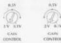
a) adjust the volume control of your head unit to 3/4 of maximum output level.
b) turn the input gain control by means of a screwdriver and adjust the input gain from 2 V to 0.1 V in order to have the maximum sound level with no distortion.
NOTE: Both adjustments are always activated, independently from the number of inputs, except in case "c" described at page 12.
OUTPUT MODE SELECTOR WITH 4 INPUT CHANNELS
a) "4CH INPUT" "4CH OUTPUT" MODE: As your head unit is equipped with four pre-amplified outputs select the position "4CH" and connect the outputs to the amplifier inputs marked with the letters A (left), B (right), C (left) and D (right). Thus, the amplifier can be used as a 4-channel stereo system, front section A and B and rear section C and D, by using the speaker outputs A, B, C and D. You can then activate independently the different sections of the built-in electronic crossover to obtain the High-Pass outputs A and B and/or the Low-Pass outputs C and D.

b) "4CH input" "3CH output" MODE: This configuration uses a single 44.13 amplifier as a multi-amplifying system. There are 3 output channels, 2 stereo channels A and B, and a third channel F with a single bridged mono signal; they can then be balanced by means of the fader control of your head unit.
In case you want to use the built-in electronic crossover, it is possible to connect medium-high speaker systems to the A and B outputs by placing the High-Pass selector in the 80/120 Hz position, whereas a woofer system or a powerful subwoofer can be connected to the output F by placing the Low-Pass selector in the 80/120 Hz position.

SETTINGS AND SELECTORS
OUTPUT MODE SELECTOR WITH 2 INPUT CHANNELS AND A BY-PASS OUTPUT
a) "2CH INPUT" "4CH OUTPUT" MODE: As your head unit is equipped with only two pre-amplified outputs select the position "2CH" and connect the outputs to the amplifier inputs marked with the letters A / E (left) and B / F (right). Then select the position "4CH" in order to have 4 output channels. A, B, C and D, respectively, to drive 4 speakers. You can then activate the different sections of the built-in electronic crossover independently to obtain the High-Pass outputs A and B and/or the Low-Pass outputs C and D. IMPORTANT NOTE: Both input sensitivity adjustments are activated and operate independently on the respective outputs.


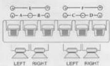
b) "2CH INPUT" "3CH OUTPUT" MODE: This configuration uses a single 44.13 amplifier as a multi-amplifying system. There are 3 output channels, 2 stereo channels A and B, and a third channel F with a single bridged mono signal. In case you want to use the built-in electronic crossover, the outputs A and B can be connected to medium-high speaker systems by placing the High-Pass selector in the 80/120 Hz position, whereas by placing the Low-Pass selector in the position 80/120 Hz a woofer system or a powerful subwoofer can be connected to the mono output F. IMPORTANT NOTE: Both input sensitivity adjustments are activated and operate independently on the respective outputs.


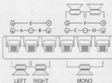
c) "2CH INPUT" "2CH OUTPUT MODE: This configuration uses the amplifier as a traditional and powerful 2-channel stereo system with the output channels E and F. On activating the electronic crossover section Low-Pass 80/120 Hz in this configuration, only the low frequencies are output for driving two powerful subwcofers. IMPORTANT NOTE: With this configuration only one of the two input sensitivity controls (the right one) is activated for the adjustment of the signal at the E (left) outputs.


TECHNICAL DATA
Maximum Power 45Wx4
Nominal RMS 4 Ohm, 20Hz to 20 kHz at 0.1% THD "4 CH Output" mode .... 30Wx4 "3 CH Output" mode .... 30Wx2 60Wx1 "2 CH Output" mode .... 60Wx2
Frequency response +0, -1dB 10-45.000 Hz
S/N IHF-A-weighted 100 dB
Crossover frequencies LOW-PASS 80-120 Hz
HIGH-PASS 80-120 Hz
Crossover slope 12dB/oct.
Input sensitivity/Impedance (for nominal power output) Control in central position (click) 500mV/10 kOhm Variable control 100-2,000 mV/10 kOhm
Speaker impedance .... 2CH 4 Ohm 3CH 2 Ohm 4 Ohm (bridged, mono) 4CH 2-4 Ohm
Power supply ( negative ground ) 14.0V DC (11-16V permissible)
Net Weigh 3.2 kg
Chassis size 235(W)x50(H)x217(D) mm
Due to continuing improvement, the features and the design are subject to charge without notice.

- 44.13
- INTRODUCTION
- PRECAUTIONS
- FEATURES
- • 4/3/2 CHANNEL OPERATION
- • NO AMPERAGE LIMITATIONS
- • INPUT MODE SELECTOR
- • OUTPUT MODE SELECTOR
- • INDEPENDENT SELECTORS FOR CROSSOVER FREQUENCIES.
- • REMOTE ON/OFF
- • RCA INPUT SENSITIVITY
- • STATUS INDICATOR
- • TRIPLE PROTECTION
- • FINAL STAGE WITH DISCREET COMPONENTS (TRANSISTORS)
- • MOS-FET SUPPLY UNIT
- CAPACITIVE/INDUCTIVE POWER SUPPLY FILTER
- \* GOLD-PLATED RCA-CONNECTORS
- \* GOLD-PLATED SCREW-TYPE SPEAKER OUTPUT CONNECTIONS
- INSTALLATION
- INSTALLATION (Fig. 1, page 3)
- CONNECTIONS
- CONNECTIONS (Fig. 2, page 4)
- CONNECTIONS (Fig. 3, pag.4)
- CONNECTIONS:
- SETTINGS AND SELECTORS
- ON/OFF MODE LOW & HIGH-PASS SELECTOR SWITCH
- INPUT GAIN ADJUSTMENT CONTROL
- OUTPUT MODE SELECTOR WITH 4 INPUT CHANNELS
- OUTPUT MODE SELECTOR WITH 2 INPUT CHANNELS AND A BY-PASS OUTPUT
- TECHNICAL DATA
Marque : Macrom
Modèle : 44.13
Catégorie : Autoradio