
CE14AT2 - Téléviseur SANYO - Notice d'utilisation et mode d'emploi gratuit
Retrouvez gratuitement la notice de l'appareil CE14AT2 SANYO au format PDF.


| Type de produit | Téléviseur CRT (tube cathodique) |
| Marque | Sanyo |
| Modèle | CE14AT2 |
| Taille de l'écran (diagonale) | 14 pouces (36 cm) |
| Dimensions (L x H x P) | Environ 36 x 34 x 38 cm |
| Poids | Environ 10 kg |
| Alimentation | 220-240 V ~ 50 Hz |
| Consommation électrique | Environ 70 W |
| Type de syntoniseur | Analogique (PAL/SECAM) |
| Entrées | Antenne RF, prise péritel (AV) |
| Fonctions principales | Télétexte, minuterie de sommeil, réglage image/son |
| Télécommande | Incluse (infrarouge) |
| Entretien et nettoyage | Utiliser un chiffon doux et sec. Ne pas utiliser de produits chimiques. |
| Sécurité | Ne pas obstruer les fentes de ventilation. Débrancher avant nettoyage. |
| Réparabilité | Pièces détachées disponibles : tube cathodique, condensateurs, résistances. |
| Nombre de pages de la notice | 20 pages |
| Langues disponibles | Français (autres langues sur demande) |
FOIRE AUX QUESTIONS - CE14AT2 SANYO
Questions des utilisateurs sur CE14AT2 SANYO
0 question sur cet appareil. Repondez a celles que vous connaissez ou posez la votre.
Poser une nouvelle question sur cet appareil
Téléchargez la notice de votre Téléviseur au format PDF gratuitement ! Retrouvez votre notice CE14AT2 - SANYO et reprennez votre appareil électronique en main. Sur cette page sont publiés tous les documents nécessaires à l'utilisation de votre appareil CE14AT2 de la marque SANYO.
MODE D'EMPLOI CE14AT2 SANYO
SANYO
CE14AT2-GB
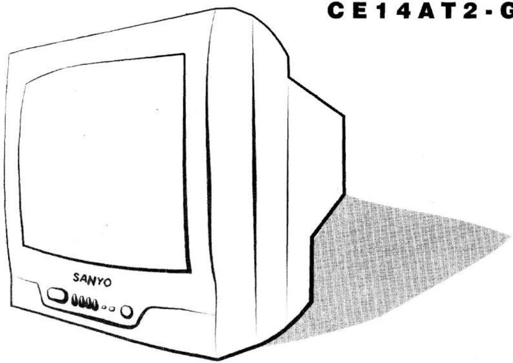
CONTENTS CONTENTS
Safety precautions 3
Installation 4
Remote control 5
Controls 5
General operation 6
Picture menu 7
Clock menu 7-8
More menu 8-9
Tuning menu 9
Presetting 10-11
Other functions 11-12
Teletext 12-14
Connection of AV equipments 14-15
Functioning 15
Especifications 16
Environment recommendations 17
Servicing 17
Helpful hints 18
Hotel mode 19
SAFETY PRECAUTIONS SAFETY PRECAUTIONS
SAFETY PRECAUTIONS SAFETY PRECAUTIONS

CAUTION: Please read and retain for your safety. This unit has been engineered and manufactured to assure your personal safety. But improper use can result in potential electrical shock or fire hazards. In order not to defeat the safeguards incorporated in this receiver, observe the following basic rules for its installation, use and servicing.

natural_image
Illustration of a steaming machine with a fish inside, emitting steam (no text or symbols)
natural_image
Illustration of a person falling off from a moving vehicle with broken legs (no text or symbols)Installation
Do not allow anything to rest on the power cord. Do not locate this television receiver where the cord will be damaged by people walking on it. Do not overload wall outlets and extension cords. Slots and openings in the cabinet and in the back or bottom must not be blocked or covered.
This television receiver should never be placed near or over a radiator or heater. Do not replace your television receiver on an unstable stand, shelf or table.
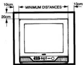


If the television is built into a unit, or enclosed, the minimum distances for ventilation must be maintained. Heat build up can reduce the life of your television and can be dangerous.
Use
This television receiver should be operated only from the type of power source indicated on the television or as indicated in the Operating Instructions. If you are not sure of the type of power supply in your home, consult your sales person or your local power company.
Never add accessories that have not been specifically designed for this television.
Do not drop or push objects into the television cabinet slots or openings. Never spill liquids of any kind on the television receiver.
Do not expose the television receiver to rain or use near water. Before cleaning, unplug the television receiver from the wall socket. Do not apply liquid cleaners or aerosol cleaners directly onto the television receiver. Use a damp cloth for cleaning.
INSTALLATION INSTALLATION
INSTALLATION INSTALLATION
Important:
This equipment is fitted with an approved non rewireable UK mains plug. To change a fuse in this type of plug proceed as follows:
- Remove the fuse cover and fuse.
- Fit a new fuse which should be a BS1362 5 Amp A.S.TA. or BSI approved type.
- Refit the fuse cover.
If the fitted plug is not suitable for your socket outlets, it should be cut off and an appropriate plug fitted in its place. If the mains plug contains a fuse, this should have a rating of 5 Amp. If a plug without a fuse is used, the fuse at the distribution board should not be greater than 5 Amp.
Note: The severed plug must be destroyed to avoid a possible shock hazard should it be inserted into a 13 Amp socket elsewhere.
The wires in this mains lead are coloured in accordance with the following code:
$$ \text { Blue } \longrightarrow \text { Neutral } $$
$$ \text { Brown } \rightarrow \text { Live } $$
- The Blue wire must be connected to the terminal which is marked with the letter "N" or coloured BLACK.
- The Brown wire must be connected to the terminal with the letter "L" or coloured RED.
- Do not connect either wire to the earth terminal in the plug which is marked with the letter "E" or by the earth symbol or coloured GREEN or GREEN and YELLOW.
Before replacing the plug cover, make certain that the cord grip is clamped over the seath of the lead - not simply over the wires.
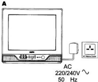
A. Mains supply
Connect the power cord of the television set to a wall outlet. When the television set is not to be used for an extended period of time, it is advisable to disconnect the power cord from the power outlet. Warning! High voltages are used in the operation of this set. Refer service to qualified service personnel.
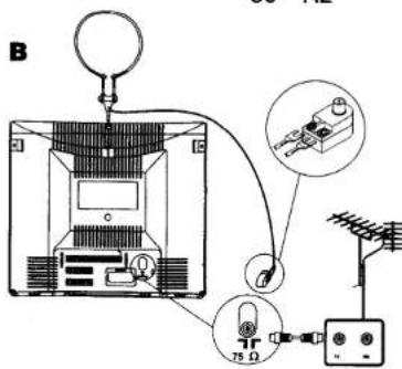
B. Aerial connection
The aerial socket is located on the back of television set. A colour picture of good quality requires a higher aerial signal than a black/white picture. If you tune your set to a station with a weak colour signal, television set automatically changes to black/white picture. For all aerial problems please consult your local dealer. For the best signal quality, the use of a well shielded antenna cable is recommended.
natural_image
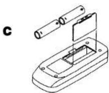
Technical line drawing of a device with a cylindrical component inserted into a housing (no text or symbols)C. Battery installation
Two "AA" 1.5 volt batteries.
REMOTE CONTROL
REMOTE CONTROL
CONTROLS
CONTROLS

CONTROLS / SYMBOLS

Function\*
- Remote control
— Stand-by / Power on
— Programme Up/Down
— Level Down/Up
Menu
— TV/AV Switch
— Sound Mute
— 0 to 9 Numeric buttons
— 2 Digit button
— Programme alternation
— Function
— Recall
— Normalisation
•TV local keyboard\*
— Mains ON/OFF switch
— Programme Up
— Programme Down
— Level Down / Up
Menu
- Connectors
— Video
— Audio
— Headphones
* See "Functions for videocassette" on page 12.
* See "Teletext controls" on pages 12-14.
* See local keyboard functioning on page 15.

GENERAL OPERATION GENERAL OPERATION
Turning the television set on/off

Introduction screen
The following message appears on the screen at the first switch on time.
Auto Sorting
When switching on the TV set for first time, it automatically begins searching, storing and sorting of all available channels, according to the following programme position:

| P1 | P2 | P3 | P4 | P5 | P6 | P7 | P8 | P9 | |
| English area | BBC1 | BBC2 | ITV | CH4 | CH5 | SKY BBC-sat | |||
| Irish area | RTE1 | RTE2 |

When the TV set detects an English bordering area, an preferably English area, or an Irish bordering area, preferably Irish, will show the following message so that you choose the way in which you want to store the programmes, according to the following order of the programme position:
| P1 | P2 | P3 | P4 | P5 | P6 | P7 | P8 | P9 | |
| English bordering area | BBC1 | BBC2 | ITV | CH4 | CH5 | SKY BBC-sat | RTE1 | RTE2 | |
| Irish bordering area | RTE1 | RTE2 | BBC1 | BBC2 | ITV | CH4 | CH5 | SKY BBC-sat |
The remaining stations will be stored from programme position 9. After completing this procedure, the ending message appears on the screen:
Auto set-up completed. Happy viewing
To make this message disappear, press any of the control buttons. If additional channels become available(you move to another city or cable is installed) you can restart the process previously explained. Go to the Tuning menu and select Auto mode (see Searching channels in Auto mode on page 10). Before the TV finds any channel, switch it off by means of the main on/off button. When you switch it on again, the TV will begin the process previously described.

GENERAL OPERATION GENERAL OPERATION

Remote ON/OFF
Standby. To turn the TV into standby mode, press the ⏻ button on the remote control unit. The power indicator illuminates more brightly.
To turn the television set on from Standby mode, press any of the following buttons: ⏻, ▲P, ▼P or numeric buttons 0-9.
NOTE: The television set cannot be turned on using the mains On/Off switch from Standby mode.


Turn off the television set using the mains On/Off switch if a power failure occurs while the TV is on.

Auto Shut Off
The TV will automatically switch into standby mode 10 minutes after a signal is no longer received. The time until the set will switch off is desplayed on the screen.
Programme Selection
A. Next / Previous programme. B. Direct programme selection from 10 to 99.

Volume adjustment
Adjust the volume using the ▲+ and -▲ buttons.
PICTUREMENU PICTUREMENU
CLOCK MENU CLOCK MENU
F/OK BUTTON
It allows the sequential access to: bright, contrast, colour, definition, volume and hue (in NTSC).
Main menu
To enter and exit the Main Menu, press the MENU button on the remote control unit.
▲P ▼P :to scroll up and down.
▲+ :to open the submenus.
- ▲+ :press to adjust the selected control level up or down.
Picture adjustment

Picture effects
- Noise coring, enabled (ON), reduces "snow" noise on the picture.
- Blue Stretch, enabled (ON), increases the proportion of blue on white picture tones.
- Black Stretch, enabled (ON), darkens greyer areas of the screen.
- Skin tone: ON/OFF.
• Colour tone. 3 colour tones can be selected: normal, "warm" or "cold" colour ranges.
Access the Main Menu and select Clock, if the clock is not adjusted, it will only find de Adjust option, if it is adjusted, then several different options will be found to set the clock, alarm and timers.
Only the remote cotrol numeric buttons are valid for these functions. You must always enter four digits when setting the time in hours and minutes (hh:mm). Any of the four options in this submenu can be reset by pressing the -▲ button.

Time Set: lets you check or set the current time, which is kept current if the TV set is not turned off using the mains ON/OFF switch. This options also lets you check the time information on the channel indicator.

Alarm Set: using the remote control unit numeric keys, you can set the TV alarm function.
CLOCK MENU CLOCK MENU
MOREMENU MOREMENU
To stop the alarm, press any button on the remote control unit, except those marked VIDEO VCR.
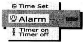
Timer On: this function lets you set the time you want the TV set to turn on when into Standby mode, using the numeric buttons of the remote control handset to set the time. The television will turn itself on at the selected time. It will turn itself off automatically if one whole hour goes by during which the remote control is not used or if no buttons are turned from the panel on the television set.

Timer Off: this function lets you set the time you want the TV set to switch into Standby mode, using the numeric buttons of the remote control handset to set the time.

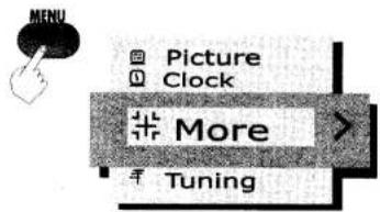
S-VHS Video: if you have an S-VHS video cassette recorder, you will obtain optimum picture quality by connecting it to the euroconnector with an appropriate cable and enabling this option.

AVL: Automatic volume level, when activated it tends to keep the volume constant. It is useful when volume increases when advertising spot are on TV.

MOREMENU MOREMENU
TUNING MENU
16:9 Format. If you have a decoder, VCR or camera which uses 16:9 format, the picture will cover the entire screen but will appear vertically stretched. This format corrects the picture proportions.

Child lock: when enabled, it locks out all local keypad operations.


natural_image
Back panel with electronic components and a black X symbol (no text or labels)Begin channel search

We may start the channel search from the Tuning submenu. As displayed on the following chart, scroll down to the 3rd option by pressing ▼P button. The band (VLF, VHF, and UHF) is selected by pressing the -/-- button and when pressing ▲+ search will begin.
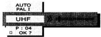
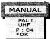
When the ☐ OK? mention appears, this will mean that the values of the current programme have not been saved or stored. The ☑ OK mention means that the displayed values have been saved in memory.
PRESETTING PRESETTING
PRESETTING PRESETTING
Different modes may be selected for the search:
Searching channels in AUTO mode
The TV set automatically searches and stores all locally accessible channels. Access the Tuning submenu and select the Auto option.
Once selected, scroll down to UHF option by pressing on ▼P button and follow the steps mentioned in the previous point.
The TV set starts scanning and stores channels in the order they are found. To change the order of stored station, use the "Channel Swapping" function on page 11.

Searching channels in SEMI mode
Acces the Tuning submenu and select the Semi option from Mode. The TV set searches for both nearby and faraway channel signals. Once this mode has been selected, scroll down to the 3rd option and begin the search by pressing ▲+ button. The Tuning indicator tells you whether you are near (<,>) or far (<<, >>) from a channel broadcast and the direction of the search. The search stops when a channel is found. The tuning indicator will read > <.

To select programme, scroll down to 4th option by using ▼P button. By pressing on ▲+ and -▲ buttons or two digits, select the programme number in which you wish to store the tuned channel.
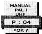
To save in memory, scroll down to the last option and select OK with + button.

Searching channels in MANUAL mode
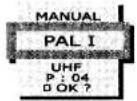
Select the Manual mode option and begin the search by keeping ▲+ or - ▲ button pressed. This option is useful for tuning faraway or weak channel signals. The following steps for programme selection and storing in memory are the same as in the semi option described above.

PRESETTING PRESETTING
OTHER FUNCTIONS OTHER FUNCTIONS
Other Tuning menu options
System: informs you of the broadcast standard that has been detected, PAL DK default option. When it has been detected, sound standard can be commuted manually by means of + and - buttons. For broadcasts in PAL BG system, you must select the PAL BG option manually.
Channel Swapping: Use this channel swapping feature to swap the channels between two stored programme position. Using the remote control handset numeric keypad, select the channel number, pressing two digits (e.g., 02) you wish to change positions with the currently selected channel. After pressing the second digit, the message OK? is displayed. To confirm press ▲+.

Fine tune: this function is available only for channels 0-9. A scrolling indicator will be displayed and we will be able to fine-tune the channels selection using the ▲+ or - ▲buttons.

NOTE: this setting disables the Auto Frequency Tracking (AFT) function and will be useful only in very special cases where signal reception is extremely poor. It is advisable to leave it always in the central position with the AFT indication enabled.

flowchart
graph TD
    A["Cityscape"] --> B["Rural landscape"]
    B --> C["P-P"]
    C --> D["Recall"]
    D --> E["Score Display"]

flowchart
graph TD
    A["Step 1: MUTE"] --> B["Step 2: MUTE"]
    B --> C["Step 3: MUTE"]
    C --> D["Step 4: MUTE"]
    style A fill:#f9f,stroke:#333
    style B fill:#ccf,stroke:#333
    style C fill:#cfc,stroke:#333
    style D fill:#fcc,stroke:#333
Alternative programme
Press the P-P button. This lets you switch back and forth between the currently selected programme position and the previously selected programme position.
Recall
To display the programme information.
Mute
Should you wish to attenuate the sound press the MUTE button down once. If you press it twice, the sound will mute totally. To switch the sound back again press: MUTE, + or - ▲.
Store/Restore default settings
If you have an adjustment of picture or volume menu displayed on screen and you wish to store the current settings as default settings, press the NORMAL button. This same button restores the original settings suggested by the manufacturer when it is pressed no menu option twice ( > < DEFAULT ).
First time it recovers the settings defined by user ( NORMAL ).
OTHER FUNCTIONS OTHER FUNCTIONS
TELETEXT TELETEXT
Functions for video cassette
You can control the basic functions of SANYO VCRs with the remote control. Some SANYO VCRs will have their own functions, so it is preferable to refer to the manual of the video itself when you use this remote control, in order to assure their compatibility.


Play button
Use this button to play back the tape.

Stop button
Use this button to stop the tape.

Fast forward
Use this button to run the tape in fast forward or to make a rapid search with the picture in forward motion.

Fast rewind
Use this button to quickly rewind the tape or to make a rapid search with the picture in reverse motion.

Remote control
Symbol Function
TXT/TV
TEXT/MIX Switch
0-9
0 to 9 Numeric buttons
APV
Page Up/Down
INDEX
Index page selection
STOP
Stop
SIZE
Size
CANCEL
Cancel
S.PAGE
Sub page button
REVEAL
Reveal

Red

Green

Yellow

Blue
LIST
List
NORMAL
Memory
Switching to the Teletext mode
Press the TXT/TV button and the screen changes as illustrated.

flowchart
graph LR
    A["P100 TXSTV 100 J25-APR 10:21:38"] --> B["TXT/TV"]
    B --> C["P100 TXSTV 100 J25-APR 10:21:38"]
    C --> D["TXT/TV"]
    D --> E["P100 TXSTV 100 J25-APR 10:21:38"]
    E --> F["TV/AV"]
    F --> A
TELETEXT TELETEXT
TELETEXT TELETEXT
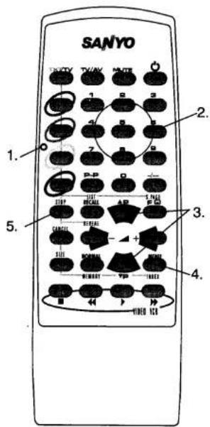
1.- Coloured button page access.

2.- Press the page number by means of numeric buttons.
3.- Up/down page access.

4.- Index page selection.

5.- Stop.
When a text page has sub pages you can prevent the sub page being automatically changed by pressing the

To resume page change, press the button again

or enter a new page number.
LIST
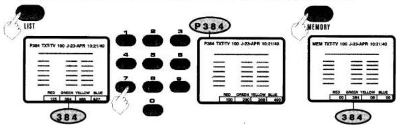
This mode, only available in the programs going from 0 to 9, provides an easy access to four teletext pages of your choice. After pressing the LIST button, proceed as follows:
1.- Press the colour button where you want to store the page.
2.- Select the page you want to store with numeric keys.
3.-Press the MEMORY button. The indicator of page number changes into MEM.
flowchart
graph TD
    A["LIST"] --> B["P384 TXT-TV 100 J-23-APR 10:21/40"]
    B --> C["1"]
    B --> D["2"]
    B --> E["3"]
    B --> F["4"]
    B --> G["5"]
    B --> H["6"]
    B --> I["7"]
    B --> J["8"]
    B --> K["9"]
    B --> L["0"]
    M["P384"] --> N["P384 TXT-TV 100 J-23-APR 10:21/40"]
    N --> O["RED GREEN YELLOW BLUE"]
    N --> P["100 GREEN YELLOW BLUE"]
    N --> Q["200 GREEN YELLOW BLUE"]
    N --> R["300 GREEN YELLOW BLUE"]
    N --> S["400 GREEN YELLOW BLUE"]
    N --> T["0"]
    U["MEMORY"] --> V["MEM TXT-TV 106 J-23-APR 10:21/40"]
    V --> W["RED GREEN YELLOW BLUE"]
    V --> X["00 GREEN YELLOW BLUE"]
    V --> Y["384"]
    V --> Z["90"]
    V --> AA["0"]
Viewing TV while searching for a page

flowchart
graph LR
    A["Hand icon"] --> B{Stop Check}
    B --> C["Hourlight icon"]
    C --> D["Stop Time 301"]
    D --> E["Stop Time 301 TXT-TV 301 J-23-APR 10:21:40"]
    E --> F["Stop Time 301 TXT-TV 301 J-23-APR 10:21:40"]
Double letter height

flowchart
graph LR
    A["1980 TXT-IV 230 J-23-APR 10:2:140 PROGRAMMING. MORNING AFTERHOOD"] --> B["1980 TXT-IV 230 J-23-APR 10:2:140 PROGRAMMING. MORNING AFTERHOOD"]
    B --> C["1980 TXT-IV 230 J-23-APR 10:2:140 PROGRAMMING. MORNING AFTERHOOD"]
    C --> D["1980 TXT-IV 230 J-23-APR 10:2:140 PROGRAMMING. MORNING AFTERHOOD"]
    D --> E["1986 TXT-IV 230 J-23-APR 10:2:140 PROGRAMMING. MORNING AFTERHOOD"]

TELETEXT
CONNECTION OF AVEQUIPMENTS CONNECTION OF AVEQUIPMENTS
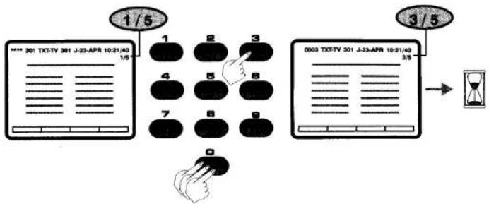
Selection of a subpage from a teletext page

- Enter the sub page number by using the (0-9) buttons. For example, to enter the sub page 3, press buttons 0,0,0 and 3.
flowchart
graph TD
    A["1/5"] --> B["1"]
    B --> C["2"]
    C --> D["3"]
    D --> E["4"]
    E --> F["5"]
    F --> G["6"]
    G --> H["7"]
    H --> I["8"]
    I --> J["9"]
    J --> K["0"]
    L["3/5"] --> M["0003 TXT-TV 301 J-23-APR 10:21:40"]
    M --> N["3/5"]
    N --> O["Hourglass icon"]
Displaying concealed information

flowchart
graph TD
    A["REVEAL"] --> B["Recall"]
    B --> C["QUIZ ???"]
    C --> D["QUIZ ANSWER"]
    D --> A
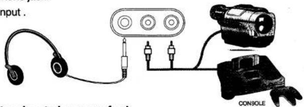
Connectors located on front of set
1. Headphone jack.
2. Front input.
Connectors located on rear of set

flowchart
graph TD
    A["TV"] --> B["VCR"]
    B --> C["VCR-SVCR"]
    B --> D["LASERDISC"]
    B --> E["R.G.B. PC"]
    B --> F["R.G.B. VIDEOTEXT"]
    C --> G["Hi-Fi"]
    D --> H["VIDEO CAMERA"]
    E --> I["SATELLITE RECEIVER"]
CONNECTION OF AVEQUIPMENTS CONNECTION OF AVEQUIPMENTS
FUNCTIONING FUNCTIONING
Connecting a VCR
- Via the antenna jack.
- Via euroconnector.


FUNCTIONING FUNCTIONING
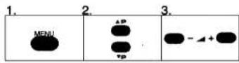
Operating the TV without the remote control
The buttons on the keypad are directly related to the corresponding buttons on the remote control unit.
1.- Button equivalencies for navigating screen menus.
2.- Switching channels.
3.- Adjusting the volume.



TV local keyboard






flowchart
graph TD
    A["Hand with M"] --> B["SET"]
    A --> C["SET"]
    B --> D["+"]
    C --> E["+"]
    D --> F["+"]
    E --> G["-"]
    F --> H["+"]
    G --> I["-"]
    H --> J["+"]
    I --> K["-"]
Change programme upwards: press SET button and ▲+ button.
Change programme downwards: press SET button and -▲ button.
Enter into menu by pressing M button, it is possible to:
- Scroll the cursor upwards, by pressing SET and ▲+ button. For instance, from Tuning control to More.
- Scroll the cursor downwards, by pressing SET and - ▲ button. For instance, from Picture control to Clock.
- By pressing ▲+ button, it is possible to enter into each of the controls; these may be modified by means of the ▲+ same button and - ▲ button.
- Press M to return to main menu.
- From local panel, press ▲+ or - ▲ to exit from standby mode.

SPECIFICATIONS SPECIFICATIONS
Scart specifications
The specification of the scart sockets are as follows:
PIN
| 1. Audio output | 0.5V/1 Kohm |
| 2. Audio input | 0.5V/10 Kohm |
| 3. Audio output | 0.5V/1 Kohm |
| 4. Audio earth | |
| 5. Earth (blue) | |
| 6. Audio input | 0.5V/1 Kohm |
| 7. Blue (B) input | 0.7Vpp/75 ohm |
| 8. Remote switch input | L:0-2V, 16/9:4.5-7V, 4/3:9.5-12V |
- Earth (green)
| 10. | |
| 11. Green (G) input | 0.7Vpp/75 ohm |
| 13. Earth (red) | |
| 14. Earth | |
| 15. Red (R) (or chrominance input) | 0.7Vpp/75 ohm |
| 16. Fast blanking | L:0-0.4V H: 1-3V |
- Earth (video)
| 18. Earth | |
| 19. Video output | 1Vpp/75 ohm |
| 20. Video sync./ (or luminance input) | 1Vpp/75 ohm |
- Connector shield

| SPECIFICATIONS | CE14AT2-GB | |
| Power source | 220-240 VAC 50 Hz | |
| Television system | I | |
| Colour system | PAL | |
| Receiving channel | UHF: 21 - E69 | |
| Aerial input impedance | 75 ohm | |
| Headphones | * | |
| Auto volume | * | |
| AV terminal 21-Pin SCARTTerminal CENELEC Standard | * | |
| AV/RCA frontal | * | |
| Sound output | 1W RMS 10% THD | |
| Picture format (4:3 / 16:9) | * | |
| Power consump. | -ON IEC conditions | 29 W |
| -Stand-by conditions | 3,1 W | |
| Teletext FLOF/LIST (1 page) | * | |
| Dimensions (mm) | W | 368 |
| H | 335,5 | |
| D | 374 | |
| Picture tube | 14" | |
| Weight (kg) | 8,7 | |
ENVIRONMENT RECOMMENDATIONS ENVIRONMENT RECOMMENDATIONS
SERVICING SERVICING
Stand-by mode: In order to save energy and to maintain an optimum picture quality, it is advisable to switch off the TV using the ON/OFF button located at the front of TV set.
Used batteries: The batteries in the remote control of your TV set do not contain mercury. However, SANYO recommends that you do not dispose of used batteries in domestic refuse. Please, contact your dealer or your local authorities for information regarding the disposal of used batteries or your nearest collection point.
Recommendation about the end-of-life: You SANYO TV set has been designed and manufactured using high quality materials which can be recycled and reused. In the future, when the life cycle of this set comes to an end, specialized companies can disassemble it and reuse certain materials. This reduces the impact of waste in our environment. Please, contact with your local authorities for information regarding the disposal of your set when the time arrives. Help us to conserve the environment we live in!
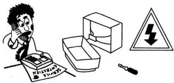
Your television is fully transistorised and does not contain any user serviceable components. Removal of the cabinet cover may expose you to dangerous voltages. Refer all servicing to qualified service personnel. Unplug the television receiver from the wall outlet and refer servicing to qualified service personnel under the following conditions:
•f the power cord or plug is damaged.
• If liquid has been spilt into the television receiver.
• If television receiver has been exposed to rain or water.
• If the television receiver has been dropped or the cabinet has been damaged.
- If the television receiver exhibits a distinct change in performance.
- If the television receiver does not operate normally by following the operating instructions.
Adjust only those controls that are covered in the operating instructions as improper adjustment of other controls may result in damage. This will often require extensive work by a qualified technician to restore the television receiver to normal operation.
When replacement parts are required, have the service technician verify that the replacements he uses have the same safety characteristics as the original parts. Use of manufacturers specified replacements can prevent fire, shock or other hazards.
HELPFUL HINTS HELPFUL HINTS
HELPFUL HINTS HELPFUL HINTS

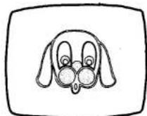
NO PICTURE, NO SOUND
- Check if television is plugged in.
- Try to switch on TV pressing the button from the remote control.
- Try a different channel, if OK, probably station trouble.

POOR PICTURE, SOUND OK
- Adjust BRIGHTNESS and CONTRAST controls.
- Check aerial connections.
NO COLOUR, PICTURE OK
- Adjust COLOUR control
• Is the programme in colour? - Verify that the option S-VHS is not enabled.
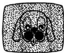
WEAK PICTURE
- Check aerial connections on back of set.
- Check aerial for broken wires.
• Re-orient aerial.
THE TELEVISION IS TURNED OFF FOR NO OBVIOUS REASON
This may be due to voltage drops in main supply.

The following faults are not caused by the receiver:
"GHOSTS"
Reflections of signals from mountains or high buildings will cause multiple images, called "Ghosts". These abnormal conditions can be reduced to minimum by repositioning aerial or by installing new one suited for your area.

"INTERFERENCE"
Interference may be caused by electrical appliances, car ignition systems, etc. This should normally be a temporary condition, but should this interference persist, contact your dealer.
HOTEL MODE HOTEL MODE
Description of "Hotel" and "Rental" modes
This mode of working is thought for its use in hotels, hospitals and another public establishments. Its features are:
• Maximum volume is limited to the level that already exists when the mode is enabled.
• There is no access to Tuning menu of channels (neither fine-tuning nor swapping, ...).
• The TV set always boots with values of normalization and it is not allowed the adjustment from the user was memorised.
• There is an access neither the language selection or child lock.
It is possible to be forced that the TV set always switch on in a certain program (between 1 and 8) or in AV1.
In order to enable this mode, hold the 'Vol-' key from the local keyboard pressed and press 'Recall' on the remote control. A message like "HOTEL: 00" will be shown, waiting for the input of two digits. The meaning of these digits is:
First digit:
'0': normal mode
'1': HOTEL mode
'2': RENTAL mode
Second digit:
'0': It switches on into the same channel as it was switched off (normal mode).
'1' to '8': It switches on into the selected programme (1 to 8).
'9': It switches on into AV1
The 'RENTAL' mode has the same features as the 'HOTEL' mode and, additionally, the keys of the local keyboard are inhibited, so it is only possible to change the programme with the remote control. In order to quit this mode, the colour saturation, it is necessary to set the saturation colour level to 0.

WARRANTY TO CUSTOMER WARRANTY TO CUSTOMER
Sanyo U.K. Sales Ltd. (the company) warrants to the initial retail purchaser that if this equipment is or becomes defective and that, in the opinion of the Company, the defect is due to faulty material or workmanship the Company will, for a period of 12 calendar months from the date of sale to the original purchaser repair or replace, at its sole option, free of charge, any such defective component part of the equipment always provided that:
1: The equipment has at all times been used in accordance with the operating instructions issued by the Company, and has not been connected to an electrical mains supply for which it has not been adjusted.
2: Accidental damage or damage caused by negligence of misuse by the user, is specifically excluded.
3: Unauthorised repairs, or any modification to the equipment which has not been expressly approved by the Company, shall render this warranty null and void.
4: Failure due to fair wear and tear of any item is specifically excluded.
This warranty is not transferable and is only applicable within the United Kingdom (and the Republic of Ireland).
Nothing in this express warranty affects the statutory rights available to the purchaser of this equipment.
Note: This warranty supersedes any other form of guarantee that may inadvertently have been enclosed with or attached to the product.
Dear customer.
Thank you for buying SANYO. This equipment should give you many years of pleasure and faithful service but in the event that a fault occurs, the following notes for you guidance may be helpful:
1: PLEASE RETAIN YOUR PURCHASE RECEIPT WHICH WILL BE REQUIRED FOR SERVICE DURING WARRANTY.
2: If your Sanyo equipment proves faulty during the period of guarantee, take it or send it back to the dealer who originally supplied it together with this guarantee and the proof of purchase. We have made arrangements with our approved dealers under which they will carry out in guarantee service repairs on our behalf. In this way, we hope to reduce to a minimum the amount of time you will be without your equipment.
3: If for some reason it is impossible to return the equipment to the original supplier, please contact our Service Department at the address below for further advice.
4: Should the equipment require servicing after the expiry of the guarantee period, take or send it to the original supplier or any other Sanyo dealer. He will be pleased to give you a quotation for the repair.
Service Department,
Sanyo UK Sales,
(A Division of SANYO Europe Ltd.),
Sanyo House,
Otterspool Way,
Watford, Hertfordshire, WD28JX.
Tel: 01923 246363
- SANYO
- CE14AT2-GB
- CONTENTS CONTENTS
- SAFETY PRECAUTIONS SAFETY PRECAUTIONS
- Installation
- Use
- INSTALLATION INSTALLATION
- Important:
- Mains supply
- Aerial connection
- Battery installation
- Function\*
- - Remote control
- •TV local keyboard\*
- - Connectors
- GENERAL OPERATION GENERAL OPERATION
- Turning the television set on/off
- Introduction screen
- Auto Sorting
- Remote ON/OFF
- Auto Shut Off
- Programme Selection
- Volume adjustment
- PICTUREMENU PICTUREMENU
- CLOCK MENU CLOCK MENU
- F/OK BUTTON
- Main menu
- Picture effects
- MOREMENU MOREMENU
- TUNING MENU
- PRESETTING PRESETTING
- Searching channels in AUTO mode
- Searching channels in SEMI mode
- Searching channels in MANUAL mode
- OTHER FUNCTIONS OTHER FUNCTIONS
- Other Tuning menu options
- Alternative programme
- Recall
- Mute
- Store/Restore default settings
- TELETEXT TELETEXT
- Functions for video cassette
- Play button
- Stop button
- Fast forward
- Fast rewind
- Remote control
- Symbol Function
- Switching to the Teletext mode
- LIST
- TELETEXT
- CONNECTION OF AVEQUIPMENTS CONNECTION OF AVEQUIPMENTS
- FUNCTIONING FUNCTIONING
- Connecting a VCR
- Operating the TV without the remote control
- TV local keyboard
- SPECIFICATIONS SPECIFICATIONS
- Scart specifications
- ENVIRONMENT RECOMMENDATIONS ENVIRONMENT RECOMMENDATIONS
- SERVICING SERVICING
- HELPFUL HINTS HELPFUL HINTS
- HOTEL MODE HOTEL MODE
- Description of "Hotel" and "Rental" modes
- First digit:
- Second digit:
- WARRANTY TO CUSTOMER WARRANTY TO CUSTOMER
- Dear customer.
Marque : SANYO
Modèle : CE14AT2
Catégorie : Téléviseur